Light MITSUBISHI LANCER EVOLUTION 2015 10.G Owner's Manual
[x] Cancel search | Manufacturer: MITSUBISHI, Model Year: 2015, Model line: LANCER EVOLUTION, Model: MITSUBISHI LANCER EVOLUTION 2015 10.GPages: 338, PDF Size: 43.12 MB
Page 49 of 338
Supplemental Restraint System (SRS) - airbag
4-24 Seat and restraint systems
4
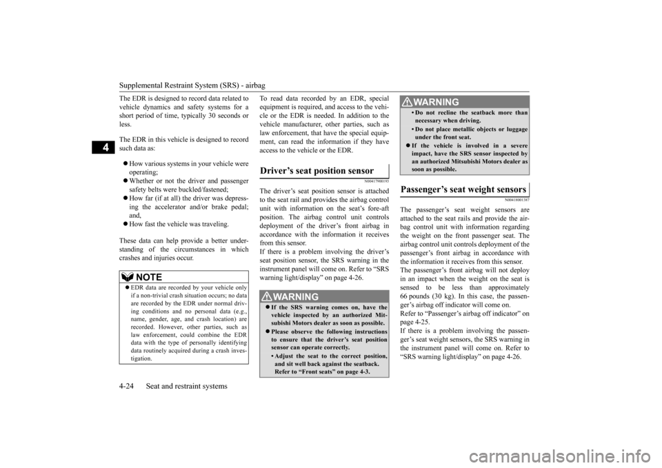
The EDR is designed to record data related to
vehicle dynamics and safety systems for a
short period of time, typically 30 seconds or
less.
The EDR in this vehicle is designed to record
such data as: How various systems in your vehicle were
operating;
Whether or not the driver and passenger
safety belts were buckled/fastened;
How far (if at all) the driver was depress-
ing the accelerator and/or brake pedal;
and,
How fast the vehicle was traveling.
These data can help provide a better under-
standing of the circumstances in which
crashes and injuries occur. To read data recorded by an EDR, special
equipment is required, and access to the vehi-
cle or the EDR is needed. In addition to the
vehicle manufacturer, other parties, such as
law enforcement, that have the special equip-
ment, can read the information if they have
access to the vehicle or the EDR.
N00417900193
The driver’s seat position sensor is attached
to the seat rail and provides the airbag control
unit with information on the seat’s fore-aft
position. The airbag control unit controls
deployment of the driver’s front airbag in
accordance with the information it receives
from this sensor.
If there is a problem involving the driver’s
seat position sensor, the SRS warning in the
instrument panel will come on. Refer to “SRS
warning light/display” on page 4-26.
N00418001387
The passenger’s seat weight sensors are
attached to the seat rails and provide the air-
bag control unit with information regarding
the weight on the front passenger seat. The
airbag control unit controls deployment of the
passenger’s front airbag in accordance with
the information it receives from this sensor.
The passenger’s front airbag will not deploy
in an impact when the weight on the seat is
sensed to be less than approximately
66 pounds (30 kg). In this case, the passen-
ger’s airbag off indicator will come on.
Refer to “Passenger’s airbag off indicator” on
page 4-25.
If there is a problem involving the passen-
ger’s seat weight sensors, the SRS warning in
the instrument panel will come on. Refer to
“SRS warning light/display” on page 4-26.
NOTE
EDR data are recorded by your vehicle only
if a non-trivial crash situation occurs; no data
are recorded by the EDR under normal driv-
ing conditions and no personal data (e.g.,
name, gender, age, and crash location) are
recorded. However, other parties, such as
law enforcement, could combine the EDR
data with the type of personally identifying
data routinely acquired during a crash inves-
tigation.
Driver’s seat position sensor
WA R N I N G If the SRS warning comes on, have the
vehicle inspected by an authorized Mit-
subishi Motors dealer as soon as possible.Please observe the following instructions
to ensure that the driver’s seat position
sensor can operate correctly.• Adjust the seat to the correct position,
and sit well back against the seatback.
Refer to “Front seats” on page 4-3.
• Do not recline the seatback more than
necessary when driving.• Do not place metallic objects or luggageunder the front seat. If the vehicle is involved in a severe
impact, have the SRS sensor inspected by
an authorized Mitsubishi Motors dealer as
soon as possible.Passenger’s seat weight sensors
WA R N I N G
SC00000500-2.fm 24 ページ 2014年4月18日 金曜日 午後5時49分
Page 51 of 338
Supplemental Restraint System (SRS) - airbag 4-26 Seat and restraint systems
4
N00408301622
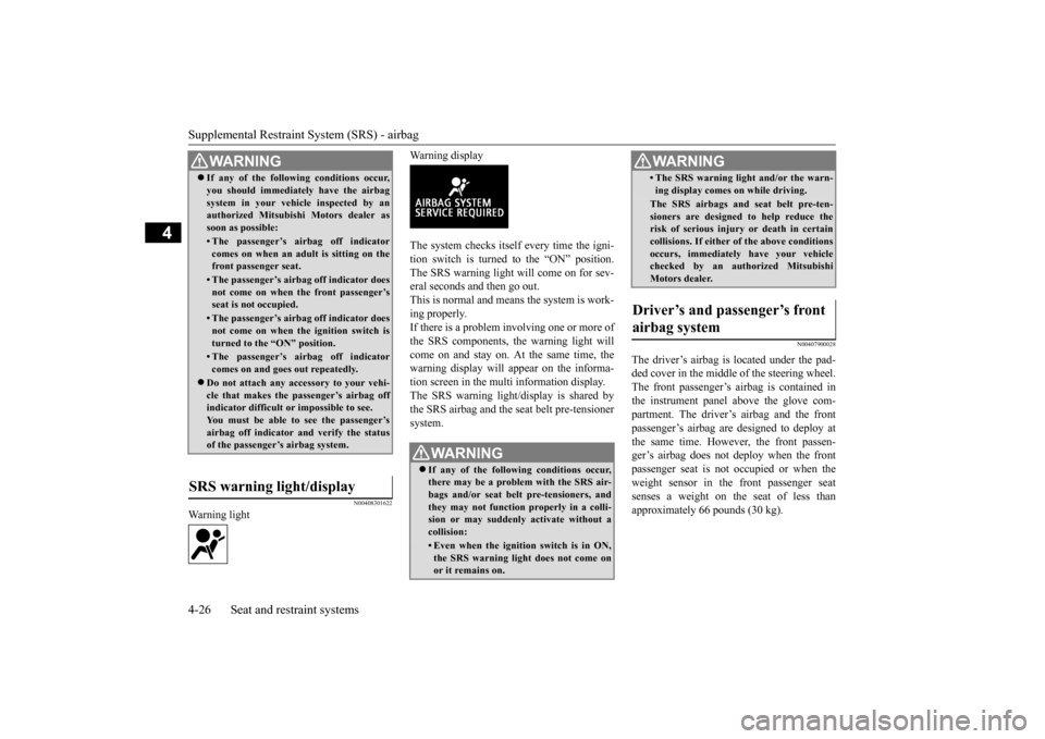
Warning light
Warning display The system checks itself every time the igni- tion switch is turned to the “ON” position. The SRS warning light will come on for sev-eral seconds and then go out. This is normal and means the system is work- ing properly.If there is a problem involving one or more of the SRS components, the warning light will come on and stay on. At the same time, thewarning display will appear on the informa- tion screen in the multi information display. The SRS warning light/display is shared bythe SRS airbag and the seat belt pre-tensioner system.
N00407900028
The driver’s airbag is located under the pad-ded cover in the middle of the steering wheel. The front passenger’s airbag is contained inthe instrument panel above the glove com- partment. The driver’s airbag and the front passenger’s airbag are designed to deploy atthe same time. However,
the front passen-
ger’s airbag does not deploy when the front passenger seat is not occupied or when theweight sensor in the front passenger seat senses a weight on the seat of less than approximately 66 pounds (30 kg).
WA R N I N G If any of the following conditions occur, you should immediately have the airbag system in your vehicle inspected by an authorized Mitsubishi Motors dealer as soon as possible:• The passenger’s airbag off indicatorcomes on when an adult is sitting on thefront passenger seat.• The passenger’s airbag off indicator doesnot come on when the front passenger’s seat is not occupied.• The passenger’s airbag off indicator doesnot come on when the ignition switch is turned to the “ON” position.• The passenger’s airbag off indicatorcomes on and goes out repeatedly.
Do not attach any accessory to your vehi- cle that makes the passenger’s airbag offindicator difficult or impossible to see. You must be able to see the passenger’s airbag off indicator and verify the statusof the passenger’s airbag system.
SRS warning light/display
WA R N I N G If any of the following conditions occur, there may be a problem with the SRS air- bags and/or seat belt pre-tensioners, and they may not function properly in a colli-sion or may suddenly activate without a collision:• Even when the ignition switch is in ON,the SRS warning light does not come on or it remains on.
• The SRS warning light and/or the warn- ing display comes on while driving.The SRS airbags and seat belt pre-ten- sioners are designed to help reduce therisk of serious injury or death in certain collisions. If either of the above conditions occurs, immediately have your vehiclechecked by an authorized Mitsubishi Motors dealer.
Driver’s and passenger’s front airbag system
WA R N I N G
BK0210800US.bo
ok 26 ページ 2014年4月8日 火曜日 午前11時28分
Page 62 of 338
5
Features and controlsBreak-in period ...............
.................................................................5-3
Keys ..........................................
.......................................................5-3
Electronic immobilizer (Anti-thef
t starting system) ........................5-4
Keyless entry system (if so equipped) ..............................................5-7Free-hand Advanced Security Transmitter (F.A.S.T.-key) (if so equipped) .
.................................................
........................ 5-11
Door locks .......................
...............................................................5-33
Power door locks ............
...............................................................5-35
“Child safety locks” for
rear door ..................................................5-36
Trunk lid ...................................
.....................................................5-37
Inside emergency trunk lid
release ................................................5-38
Theft-alarm system
................................................
........................5-39
Power windows ...............
...............................................................5-42
Sunroof (if so equipped
) .........................................
........................5-44
Parking brake ..................
...............................................................5-46
Steering wheel tilt lock lever .........................................................5-47Inside day/night rearview
mirror ...................................................5-48
Outside rearview mirr
ors ...............................................................5-49
Ignition switch ......
.................................................
........................5-50
Steering wheel lock
................................................
........................5-52
Starting and stopping the e
ngine ....................................................5-52
Turbocharger operation
..........................................
........................5-55
Clutch pedal operation (if so equipped)..........................................5-56Manual transaxle (if so equipped) ..................................................5-56 Twin Clutch SST (Sportronic Shift Transmission) (if so equipped) .
.................................................
........................5-58
All-wheel drive system
..........................................
........................5-70
Cautions on handling of all-wheel drive vehicles ..........................5-70
S-AWC (Super-All Wheel C
ontrol) ............................................... 5-71
Anti-lock braking syst
em .....................................
......................... 5-74
Active stability control
(ASC) ....................
................................... 5-76
Limited-slip differenti
al ..............................
................................... 5-78
Service brake .................
.................................................
............... 5-79
Brake assist system
...............................................
......................... 5-80
Power steering system
..........................................
......................... 5-80
Cruise control ................
.................................................
............... 5-80
Tire pressure monitoring
system ................................................... 5-85
Instrument cluster
.................................................
......................... 5-89
Multi-information disp
lay ....................................
......................... 5-90
Indicator light, warning light, and information screen display list ...........................
.................................................... 5-110
Indicators .................................
.................................................... 5-120
Warning lights ................
.................................................
............. 5-121
Information screen disp
lay ...................................
....................... 5-122
Combination headlights and dimmer switch ............................... 5-124 Turn signal lever ..
.................................................
....................... 5-129
Hazard warning flasher
switch .................................................... 5-130
Front fog light switch
...........................................
....................... 5-130
Wiper and washer swit
ch ......................................
....................... 5-131
Electric rear window def
ogger switch ......................................... 5-135
Horn switch .............................
.................................................... 5-136
Link System .............................
.................................................... 5-136
Bluetooth
® 2.0 interface ..........
.................................................... 5-136
USB input terminal
...............................................
....................... 5-157
Sun visors ......................
.................................................
............. 5-160
12 V power outlet ..........
.................................................
............. 5-160
BK0210800US.bo
ok 1 ページ 2014年4月8日 火曜日 午前11時28分
Page 63 of 338
5
Features and controlsInterior lights ......
.................................................
........................ 5-161
Storage spaces ..............
............................................................... 5-163
Cup holder ..............................
..................................................... 5-165
Bottle holder .................
............................................................... 5-165
Assist grip .....................
............................................................... 5-166
Coat hook ...............................
..................................................... 5-166
BK0210800US.bo
ok 2 ページ 2014年4月8日 火曜日 午前11時28分
Page 64 of 338
Break-in period
Features and controls 5-3
5
N00508700301
For future performance and economy of your vehicle, we recommend that you carry out thefollowing precautions. Avoid revving the engine. Do not exceed 5,000 rpm for the first 600 miles (1,000 km). Avoid rough driving such as fast starts, prolonged high-speed driving and rough shifting for the first 300 miles (500 km). The high-performance brake pads on your vehicle require a short break-in period. Avoid hard braking fo
r the first 300 miles
(500 km) to prevent future abnormalbrake noise and vibration from your vehi- cle’s brake pads. The standard-equipment tires use a high- grip compound. Thus drive with extra care for the first 200 miles (300 km). Do not overload the vehicle. Observe the seating capacity (See “Cargo loads pre- cautions” on page 6-10). Do not use this vehicle for trailer towing.
N00508800588
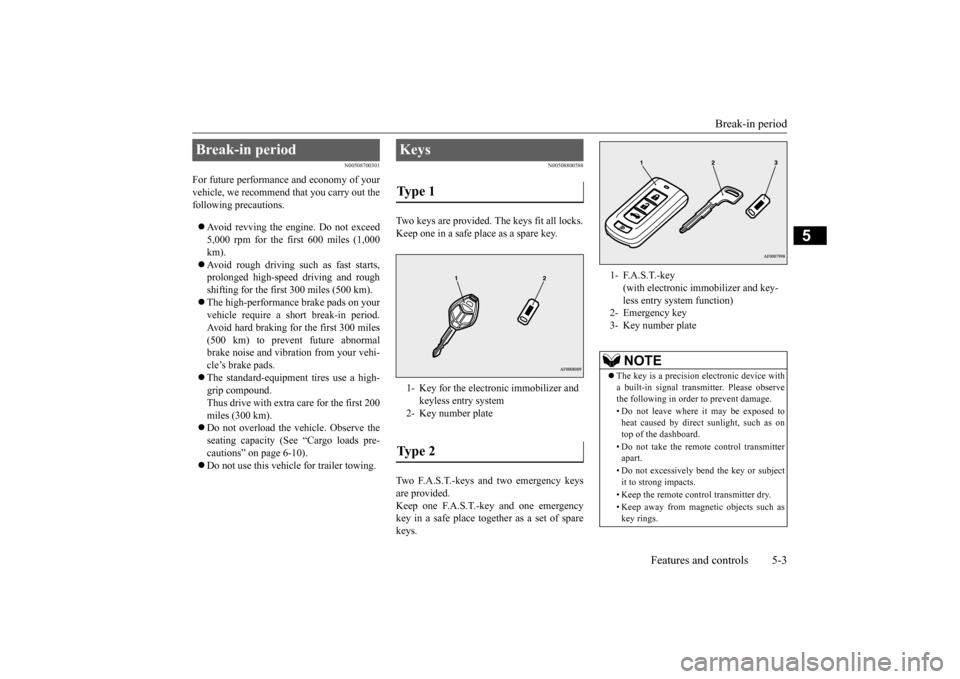
Two keys are provided. The keys fit all locks. Keep one in a safe place as a spare key. Two F.A.S.T.-keys and two emergency keys are provided.Keep one F.A.S.T.-key and one emergency key in a safe place together as a set of spare keys.
Break-in period
Keys Type 1 1- Key for the electronic immobilizer and
keyless entry system
2- Key number plateType 2
1- F.A.S.T.-key
(with electronic immobilizer and key- less entry system function)
2- Emergency key3- Key number plate
NOTE
The key is a precision electronic device with a built-in signal transmitter. Please observe the following in order to prevent damage. • Do not leave where it may be exposed to heat caused by direct sunlight, such as on top of the dashboard. • Do not take the remote control transmitter apart. • Do not excessively bend the key or subject it to strong impacts. • Keep the remote control transmitter dry. • Keep away from magnetic objects such as key rings.
BK0210800US.bo
ok 3 ページ 2014年4月8日 火曜日 午前11時28分
Page 68 of 338
Keyless entry system (if so equipped)
Features and controls 5-7
5
Operation is subject to the following two con- ditions. This device may not cause harmful inter- ference. This device must accept any interference received, including interference that may cause undesired operation.
N00509000835
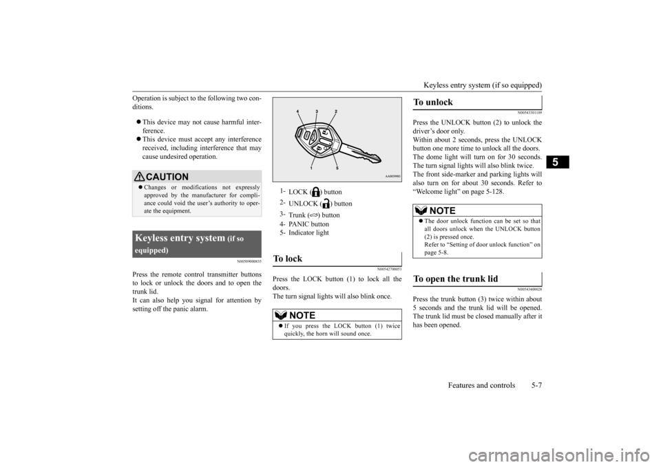
Press the remote control transmitter buttonsto lock or unlock the doors and to open the trunk lid.It can also help you signal for attention by setting off the panic alarm.
N00542700053
Press the LOCK button (1) to lock all the doors.The turn signal lights will also blink once.
N00543301109
Press the UNLOCK button (2) to unlock thedriver’s door only.Within about 2 seconds, press the UNLOCK button one more time to unlock all the doors. The dome light will turn on for 30 seconds.The turn signal lights will also blink twice. The front side-marker and parking lights will also turn on for about 30 seconds. Refer to“Welcome light” on page 5-128.
N00543400028
Press the trunk button (3) twice within about 5 seconds and the trunk lid will be opened. The trunk lid must be closed manually after ithas been opened.
CAUTION Changes or modifications not expressly approved by the manufacturer for compli- ance could void the user’s authority to oper- ate the equipment.
Keyless entry system
(if so
equipped)
1-
LOCK ( ) button
2-
UNLOCK ( ) button
3-
Trunk ( ) button
4- PANIC button 5- Indicator lightTo l o c k
NOTE
If you press the LOCK button (1) twice quickly, the horn will sound once.
To u n l o c k
NOTE
The door unlock function can be set so that all doors unlock when the UNLOCK button (2) is pressed once.Refer to “Setting of door unlock function” on page 5-8.
To open the trunk lid
BK0210800US.bo
ok 7 ページ 2014年4月8日 火曜日 午前11時28分
Page 69 of 338
Keyless entry system (if so equipped) 5-8 Features and controls
5
N00543501097
Setting of the horn and turn signal lights of the keyless entry system answerback functioncan be changed as required. This is done with the key removed from the ignition switch. The horn answerback function can be set to the following three conditions. Each time the horn answerback function isset, a chime will sound to tell you the condi- tion of the answerback function. 1. Remove the key from the ignition switch.
2. Open the driver’s door and turn the com- bination headlights and dimmer switch to the “OFF” position. 3. Press the LOCK button (1) for 4 to 10 sec-onds and press the UNLOCK button (2) during this time. 4. Release in sequence the UNLOCK andLOCK buttons within 10 seconds of pressing the UNLOCK button in step 3.
The turn signal lights answerback function can be set to the following seven conditions.Each time the turn signal lights answerback function is set, a chime will sound to tell you the condition of the answerback function.
1. Remove the key from the ignition switch. 2. Open the driver’s door and turn the com- bination headlights and dimmer switch to the “OFF” position.3. Press the UNLOCK button (2) for 4 to 10 seconds and press the LOCK button (1) during this time.4. Release in sequence the UNLOCK and LOCK buttons within 10 seconds of pressing the LOCK button in step 3.
N00543601131
The door unlock function can be set to the following two conditions. Each time the door unlock function is set, achime will sound to te
ll you the condition of
the door unlock function. 1. Remove the key from the ignition switch. 2. Open the driver’s door and turn the com-bination headlights and dimmer switch to the “OFF” position. 3. Press the LOCK button (1) for 4 to 10 sec-onds and press the UNLOCK button (2) during this time.
Answerback function
NOTE
The answerback function does not operate when the key is in the ignition switch or any doors is opened.
Horn deactivation/reactivation
Number of chimes
Condition
One chime The horn will not sound. Two chimes The horn will sound. Four chimes
The horn will sound if the LOCK button (1) is pressed twice quickly.
Changing the setting of the turn signal lights answerback function
Number of chimes
Condition
To l o c k
To u n l o c k
One chime One flash Two flashesTwo chimes One flash No flashThree chimes No flash Two flashesFour chimes Two flashes One flashFive chimes No flash One flashSix chimes Two flashes No flashSeven chimes No flash No flash
Setting of door unlock function
Number of chimes
Condition
One chime All doors unlock Two chimes Driver’s door unlock only
BK0210800US.bo
ok 8 ページ 2014年4月8日 火曜日 午前11時28分
Page 70 of 338
Keyless entry system (if so equipped)
Features and controls 5-9
5
4. Release in sequence the LOCK and UNLOCK buttons within 10 seconds of pressing the LOCK button in step 3.
N00543700047
If you are near your vehicle and feel threat-ened, you may activate the alarm to call atten- tion as follows: 1. Press the PANIC button (4) for more than 1 second.2. The headlights will blink on and off and the horn will sound intermittently for about 3 minutes.3. To turn off the alarm, press any button on the remote control transmitter.
N00543800022
Only remote control transmitters pro- grammed with the vehicle’s electronics canlock or unlock all doors. If you lose the remote control transmitter, you can order a remote control transmitter from an authorized Mitsubishi Motors dealer byreferring to the key number.
To prevent vehicle theft, the ID codes for all the remote control transmitters except the one for the lost key must be programmed again. Take your vehicle and all the remainingremote control transmitters to an authorized Mitsubishi Motors dealer to have your ID codes programmed again.
N00543900023
To add a remote control transmitter, you mustalready have one registered remote controltransmitter. Registering the ID code can be done by your- self or by your authorized Mitsubishi Motorsdealer. For you to register the ID code your- self, follow the “Customer remote control transmitter programming” procedure below.If you choose to have an authorized Mitsubi- shi Motors dealer register the ID code, take your vehicle and all remaining keys to anauthorized Mitsubishi Motors dealer.
N00544001132
You can program new remote control trans-mitters to the system if you have one valid (already registered) remote control transmit- ter by doing the following: 1. Have available all (current and new) remote control transmitters you wish toregister. 2. With a valid (already registered) remote control transmitter, press the UNLOCKbutton (2) for 4 to 10 seconds. Then press and hold the LOCK button (1). 3. Within 10 seconds of pressing the LOCKbutton, release the LOCK and UNLOCK buttons in sequence. At this time, ID codes for all remote control transmittersexcept for the transmitter used in steps 2 and 3 are erased and the answerback func- tion (door is locked and unlocked)informs you that the registration mode has been activated. 4. Within 60 seconds after step 3, completethe following ID code registration opera- tion using the next remote control trans- mitter you wish to register within 4seconds. i. Press both the LOCK and UNLOCK buttons for 2 seconds.
Using the panic alarm
Replacement remote control transmitters
Additional remote control transmitters
NOTE
You are provided with two remote control transmitters, but you may register up to eight remote control transmitters.
Customer remote control trans- mitter programming
BK0210800US.bo
ok 9 ページ 2014年4月8日 火曜日 午前11時28分
Page 71 of 338
Keyless entry system (if so equipped) 5-10 Features and controls
5
ii. Release both the LOCK and UNLOCK buttons for 1 second.
iii. Press the UNLOCK button. The
answerback function informs you thatthe ID code registra
tion of the transmit-
ter is completed.
5. To register the ID codes of additionalremote control transmitters, repeat step 4 within 60 seconds after step 4. 6. If no ID code of a remote control trans-mitter is registered within 60 secondsafter step 4, the registration mode is can- celed and the normal mode returns.
N0054610
1111
Your keyless entry system operates on a radio frequency subject to Federal Communica- tions Commission (FCC) Rules (For vehicles sold in U.S.A.) and Industry Canada Rules(For vehicles sold in Canada). This device
complies with Part 15 of FCC Rules and Industry Canada licence-exempt RSS stan- dard(s). Operation is subject to the following two con-ditions. This device may not cause harmful inter- ference. This device must accept any interference received, including interference that may cause undesired operation.
N00544100107
1. Before replacing the battery, remove static electricity from your body by touching ametal grounded object. 2. With the Mitsubishi mark facing you, insert the cloth-covered tip of a flat bladescrewdriver into the notch in the remote control transmitter case and use it to open the case.
NOTE
For verification purposes, try to lock and unlock the doors after the registration iscompleted. The indicator light (5) comes on each time a button is pressed. The keyless entry system does not work if the key is in the ignition switch. The remote control transmitter can be used from about 40 feet (12 m) away. However, this distance may change if your vehicle is near a TV transmitting tower, a power sta- tion, or a radio station. If the UNLOCK button (2) is pressed when all doors are locked and no doors are opened within about 30 seconds, the doors will auto-matically re-lock.
If the following conditions are observed after pressing the buttons on the remote control transmitter, the battery in the remote control transmitter may need to be replaced. • The doors cannot be locked or unlocked. • The trunk lid cannot be opened.• The panic alarm cannot be operated. • The indicator light (5) is dim or does not come on.
If you lose your remote control transmitter, please contact an authorized Mitsubishi Motors dealer for a replacement. If you wish to obtain an additional remote control transmitter, please contact an autho-rized Mitsubishi Motors dealer. A maximum of eight remote control transmitters can be programmed for your vehicle. To use the new remote control transmitters, it is necessary to register the key with both theelectronic immobilizer and keyless entry sys- tem. Also refer to “Electr
onic immobilizer (Anti-
theft starting system): Customer key pro- gramming” on page 5-6.
General information
NOTE
CAUTION Changes or modifications not expressly approved by the manufacturer for compli- ance could void the user’s authority to oper- ate the equipment.
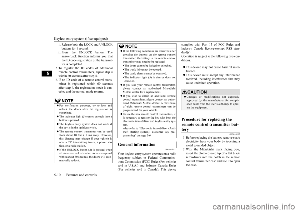
Procedure for replacing the remote control transmitter bat- tery
BK0210800US.bo
ok 10 ページ 2014年4月8日 火曜日 午前11時28分
Page 75 of 338
Free-hand Advanced Security Transmitter (F.A.S.T.-key) (if so equipped) 5-14 Features and controls
5
N00503300038
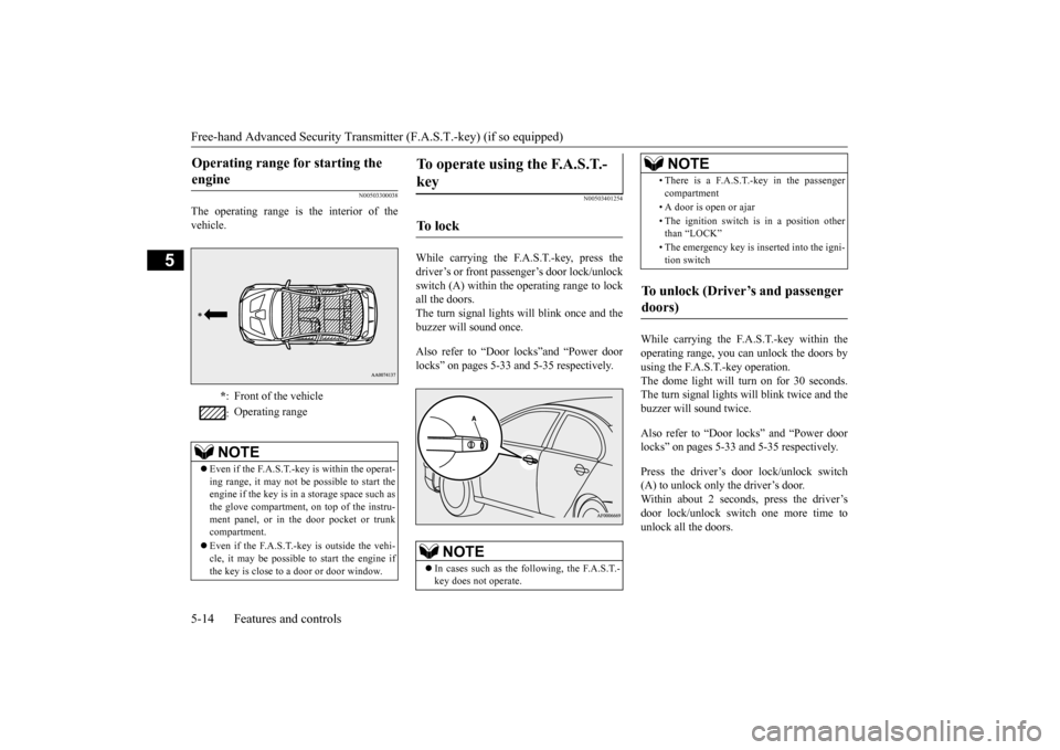
The operating range is the interior of the vehicle.
N00503401254
While carrying the F.A.S.T.-key, press the driver’s or front passenger’s door lock/unlock switch (A) within the operating range to lock all the doors.The turn signal lights will blink once and thebuzzer will sound once. Also refer to “Door locks”and “Power door locks” on pages 5-33 and 5-35 respectively.
While carrying the F.A.S.T.-key within the operating range, you can unlock the doors byusing the F.A.S.T.-key operation. The dome light will turn on for 30 seconds. The turn signal lights will blink twice and thebuzzer will sound twice. Also refer to “Door locks” and “Power door locks” on pages 5-33 and 5-35 respectively. Press the driver’s door lock/unlock switch (A) to unlock only the driver’s door.Within about 2 seconds, press the driver’s door lock/unlock switch one more time to unlock all the doors.
Operating range for starting the engine
* : Front of the vehicle : Operating range
NOTE
Even if the F.A.S.T.-key is within the operat- ing range, it may not be possible to start the engine if the key is in a storage space such asthe glove compartment, on top of the instru- ment panel, or in the door pocket or trunk compartment. Even if the F.A.S.T.-key is outside the vehi- cle, it may be possible
to start the engine if
the key is close to a door or door window.
To operate using the F.A.S.T.- key
To l o c k
NOTE
In cases such as the following, the F.A.S.T.- key does not operate.
• There is a F.A.S.T.-key in the passenger compartment • A door is open or ajar • The ignition switch is in a position other than “LOCK” • The emergency key is inserted into the igni- tion switch
To unlock (Driver’s and passenger doors)
NOTE
BK0210800US.bo
ok 14 ページ 2014年4月8日 火曜日 午前11時28分