check engine light MITSUBISHI LANCER EVOLUTION IX 2005 Workshop Manual
[x] Cancel search | Manufacturer: MITSUBISHI, Model Year: 2005, Model line: LANCER EVOLUTION IX, Model: MITSUBISHI LANCER EVOLUTION IX 2005Pages: 364, PDF Size: 14.38 MB
Page 30 of 364

ENGINE – TIMING BELT, TIMING BELT B11-24
2.
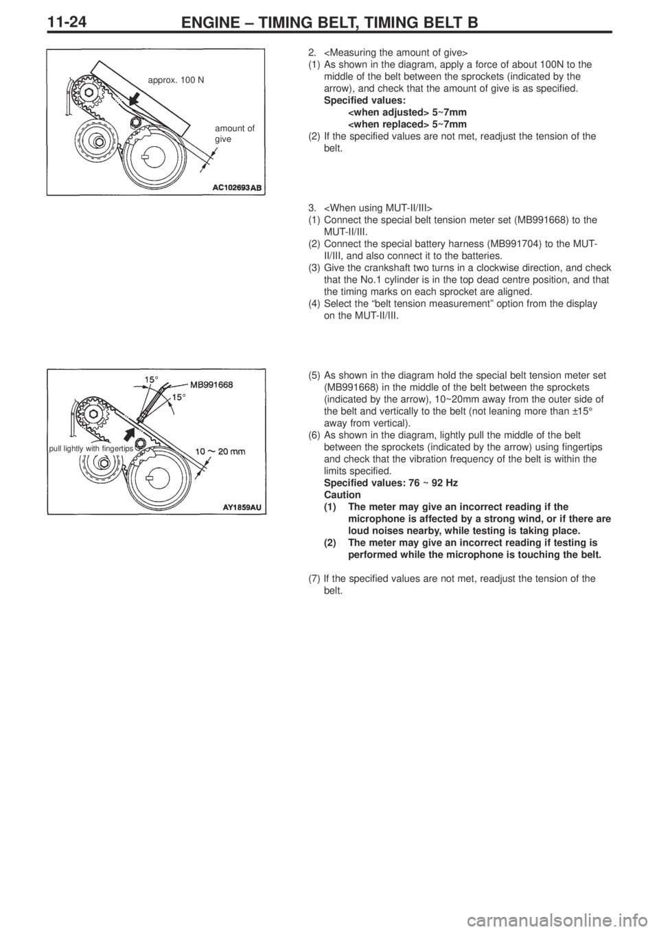
(1) As shown in the diagram, apply a force of about 100N to the
middle of the belt between the sprockets (indicated by the
arrow), and check that the amount of give is as specified.
Specified values:
(2) If the specified values are not met, readjust the tension of the
belt.
3.
(1) Connect the special belt tension meter set (MB991668) to the
MUT-II/III.
(2) Connect the special battery harness (MB991704) to the MUT-
II/III, and also connect it to the batteries.
(3) Give the crankshaft two turns in a clockwise direction, and check
that the No.1 cylinder is in the top dead centre position, and that
the timing marks on each sprocket are aligned.
(4) Select the “belt tension measurement” option from the display
on the MUT-II/III.
(5) As shown in the diagram hold the special belt tension meter set
(MB991668) in the middle of the belt between the sprockets
(indicated by the arrow), 10~20mm away from the outer side of
the belt and vertically to the belt (not leaning more than ±15°
away from vertical).
(6) As shown in the diagram, lightly pull the middle of the belt
between the sprockets (indicated by the arrow) using fingertips
and check that the vibration frequency of the belt is within the
limits specified.
Specified values: 76 ~ 92 Hz
Caution
(1) The meter may give an incorrect reading if the
microphone is affected by a strong wind, or if there are
loud noises nearby, while testing is taking place.
(2) The meter may give an incorrect reading if testing is
performed while the microphone is touching the belt.
(7) If the specified values are not met, readjust the tension of the
belt.
approx. 100 N
amount of
give
pull lightly with fingertips
Page 42 of 364

MPI – GENERAL13A-2
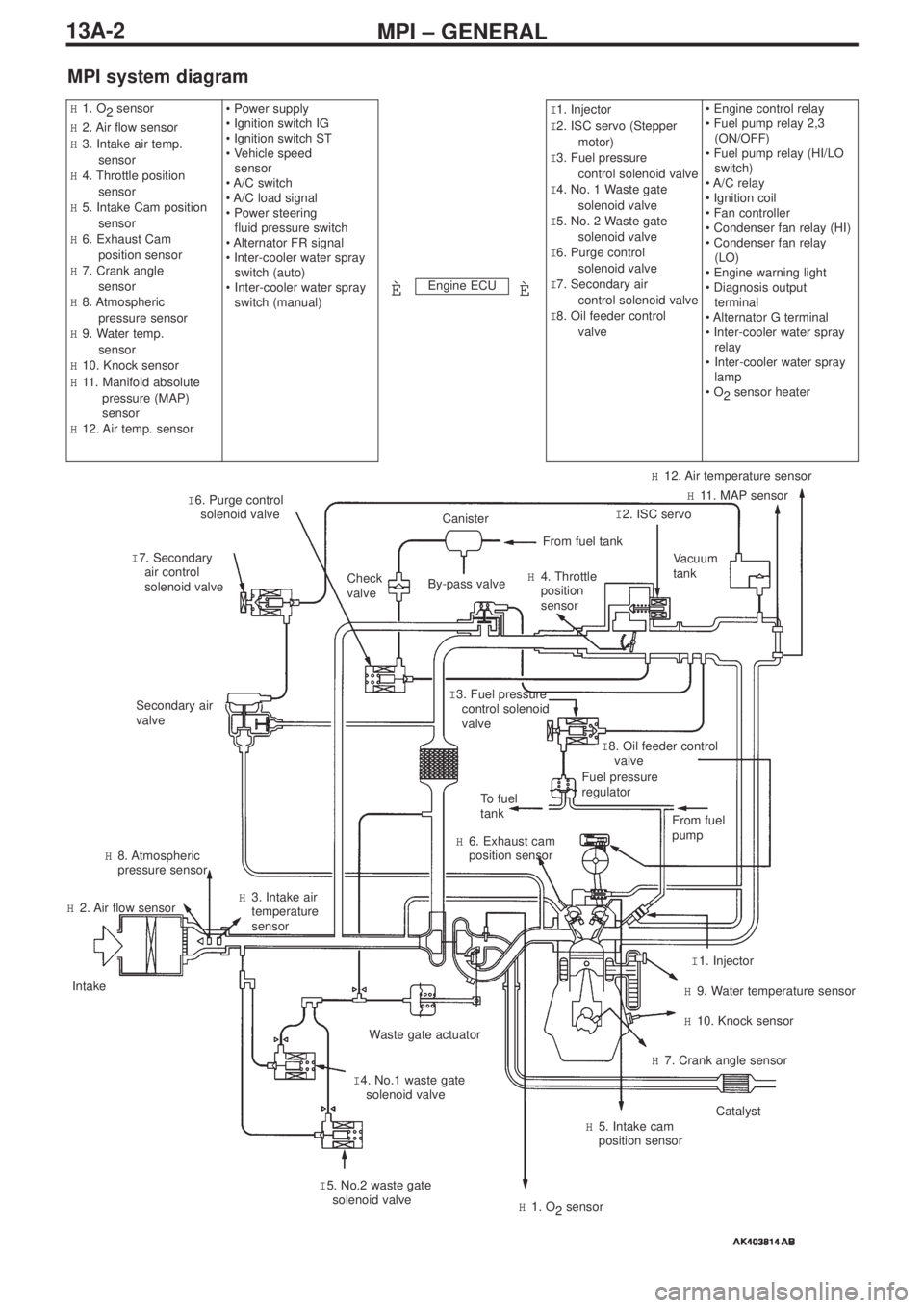
MPI system diagram
Engine ECU
H1. O
2 sensor
H2. Air flow sensor
H3. Intake air temp.
sensor
H4. Throttle position
sensor
H5. Intake Cam position
sensor
H6. Exhaust Cam
position sensor
H7. Crank angle
sensor
H8. Atmospheric
pressure sensor
H9. Water temp.
sensor
H10. Knock sensor
H11. Manifold absolute
pressure (MAP)
sensor
H12. Air temp. sensor• Power supply
• Ignition switch IG
• Ignition switch ST
• Vehicle speed
sensor
• A/C switch
• A/C load signal
• Power steering
fluid pressure switch
• Alternator FR signal
• Inter-cooler water spray
switch (auto)
•Inter-cooler water spray
switch (manual)I1. Injector
I2. ISC servo (Stepper
motor)
I3. Fuel pressure
control solenoid valve
I4. No. 1 Waste gate
solenoid valve
I5. No. 2 Waste gate
solenoid valve
I6. Purge control
solenoid valve
I7. Secondary air
control solenoid valve
I8. Oil feeder control
valve• Engine control relay
• Fuel pump relay 2,3
(ON/OFF)
• Fuel pump relay (HI/LO
switch)
• A/C relay
• Ignition coil
• Fan controller
• Condenser fan relay (HI)
• Condenser fan relay
(LO)
• Engine warning light
• Diagnosis output
terminal
• Alternator G terminal
• Inter-cooler water spray
relay
•Inter-cooler water spray
lamp
• O
2sensor heater
ÈÈ
I 6. Purge control
solenoid valve
I 7. Secondary
air control
solenoid valveCheck
valve
Secondary air
valve
To fuel
tank
H 6. Exhaust cam
position sensor
H 8. Atmospheric
pressure sensor
H 2. Air flow sensor
Intake
Waste gate actuator
I 4. No.1 waste gate
solenoid valve H 3. Intake air
temperature
sensor
I 5. No.2 waste gate
solenoid valve
H 1. O
2sensor
H 5. Intake cam
position sensorCatalyst
H 7. Crank angle sensor
H 10. Knock sensor
H 9. Water temperature sensor
I 1. Injector From fuel
pump
Fuel pressure
regulatorI 8. Oil feeder control
valve I 3. Fuel pressure
control solenoid
valve
Vacuum
tank
I 2. ISC servoH 11. MAP sensor
H 12. Air temperature sensor
H 4. Throttle
position
sensor
From fuel tank
Canister
By-pass valve
Page 45 of 364

MPI – TROUBLESHOOTING
13A-5
TROUBLESHOOTING
1. Diagnosis Functions
1-1 Engine warning light (Check engine lamp)
Changes have been made to engine warning lights.
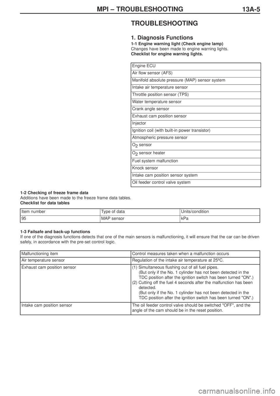
Checklist for engine warning lights.
1-2 Checking of freeze frame data
Additions have been made to the freeze frame data tables.
Checklist for data tables
1-3 Failsafe and back-up functions
If one of the diagnosis functions detects that one of the main sensors is malfunctioning, it will ensure that the car can be driven
safely, in accordance with the pre-set control logic.
Engine ECU
Air flow sensor (AFS)
Manifold absolute pressure (MAP) sensor system
Intake air temperature sensor
Throttle position sensor (TPS)
Water temperature sensor
Crank angle sensor
Exhaust cam position sensor
Injector
Ignition coil (with built-in power transistor)
Atmospheric pressure sensor
O
2sensor
O
2sensor heater
Fuel system malfunction
Knock sensor
Intake cam position sensor system
Oil feeder control valve system
Item numberType of data Units/condition
95MAP sensorkPa
Malfunctioning itemControl measures taken when a malfunction occurs
Air temperature sensorRegulation of the intake air temperature at 25ºC.
Exhaust cam position sensor(1) Simultaneous flushing out of all fuel pipes.
(But only if the No. 1 cylinder has not been detected in the
TDC position after the ignition switch has been turned "ON".)
(2) Cutting off the fuel 4 seconds after the malfunction has been
detected.
(But only if the No. 1 cylinder has not been detected in the
TDC position after the ignition switch has been turned "ON".)
Intake cam position sensorThe oil feeder control valve should be switched "OFF", and the
angle of the cam should be in the reset position.