diagram MITSUBISHI LANCER EVOLUTION VIII 2004 Owner's Manual
[x] Cancel search | Manufacturer: MITSUBISHI, Model Year: 2004, Model line: LANCER EVOLUTION VIII, Model: MITSUBISHI LANCER EVOLUTION VIII 2004Pages: 166, PDF Size: 3.56 MB
Page 102 of 166
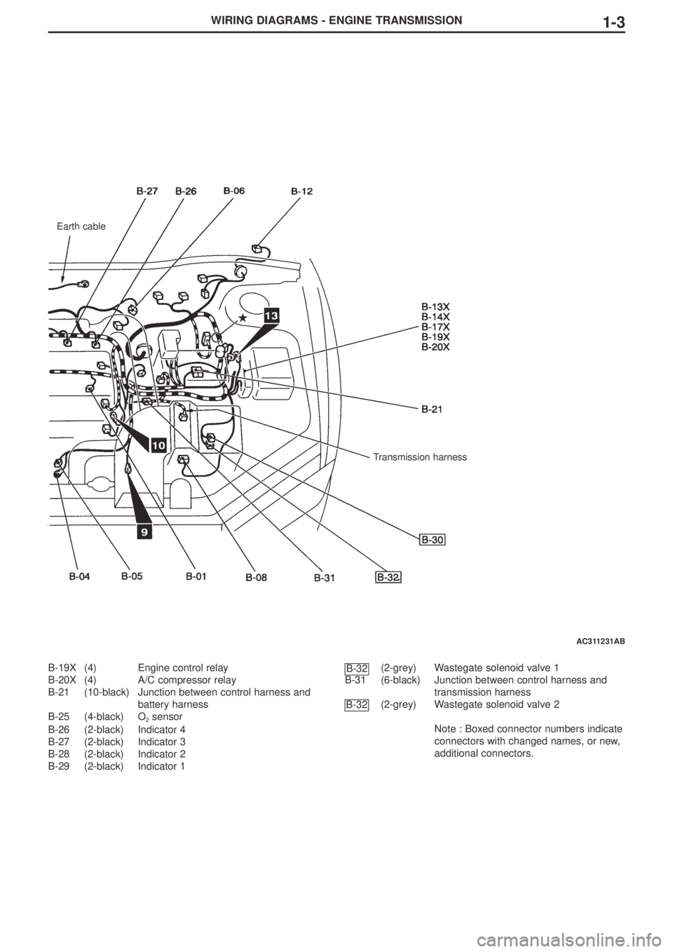
WIRING DIAGRAMS - ENGINE TRANSMISSION1-3
B-19X (4) Engine control relay
B-20X (4) A/C compressor relay
B-21 (10-black) Junction between control harness and
battery harness
B-25 (4-black) O
2sensor
B-26 (2-black) Indicator 4
B-27 (2-black) Indicator 3
B-28 (2-black) Indicator 2
B-29 (2-black) Indicator 1(2-grey) Wastegate solenoid valve 1
B-31 (6-black) Junction between control harness and
transmission harness
(2-grey) Wastegate solenoid valve 2
Note : Boxed connector numbers indicate
connectors with changed names, or new,
additional connectors.
B-32
B-32
Earth cable
Transmission harness
AC311231AB
Page 103 of 166
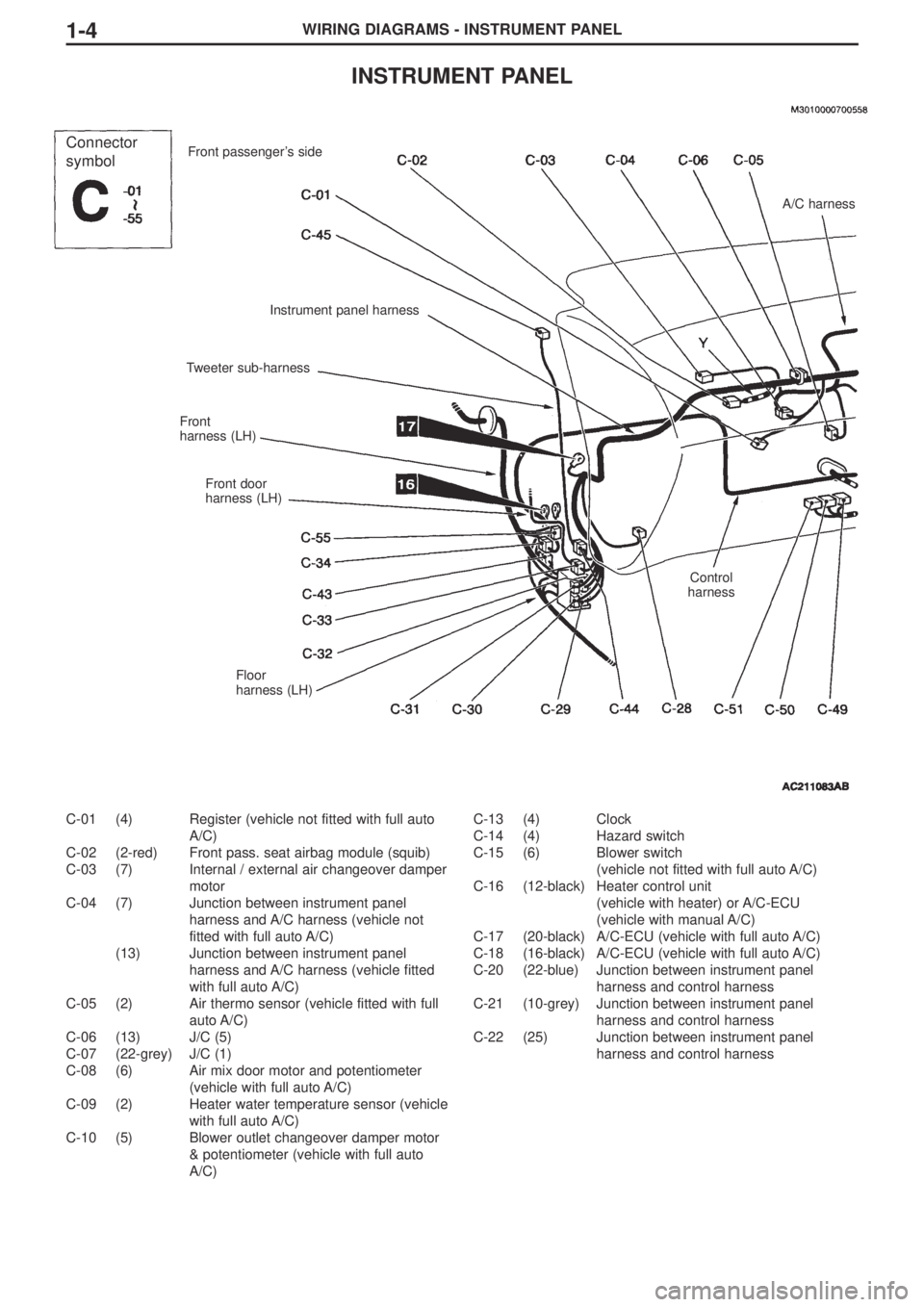
WIRING DIAGRAMS - INSTRUMENT PANEL1-4
INSTRUMENT PANEL
C-01 (4) Register (vehicle not fitted with full auto
A/C)
C-02 (2-red) Front pass. seat airbag module (squib)
C-03 (7) Internal / external air changeover damper
motor
C-04 (7) Junction between instrument panel
harness and A/C harness (vehicle not
fitted with full auto A/C)
(13) Junction between instrument panel
harness and A/C harness (vehicle fitted
with full auto A/C)
C-05 (2) Air thermo sensor (vehicle fitted with full
auto A/C)
C-06 (13) J/C (5)
C-07 (22-grey) J/C (1)
C-08 (6) Air mix door motor and potentiometer
(vehicle with full auto A/C)
C-09 (2) Heater water temperature sensor (vehicle
with full auto A/C)
C-10 (5) Blower outlet changeover damper motor
& potentiometer (vehicle with full auto
A/C)C-13 (4) Clock
C-14 (4) Hazard switch
C-15 (6) Blower switch
(vehicle not fitted with full auto A/C)
C-16 (12-black) Heater control unit
(vehicle with heater) or A/C-ECU
(vehicle with manual A/C)
C-17 (20-black) A/C-ECU (vehicle with full auto A/C)
C-18 (16-black) A/C-ECU (vehicle with full auto A/C)
C-20 (22-blue) Junction between instrument panel
harness and control harness
C-21 (10-grey) Junction between instrument panel
harness and control harness
C-22 (25) Junction between instrument panel
harness and control harness
Connector
symbolFront passenger’s side
Instrument panel harness
Tweeter sub-harness
Front
harness (LH)
Front door
harness (LH)
Floor
harness (LH)
A/C harness
Control
harness
Page 104 of 166
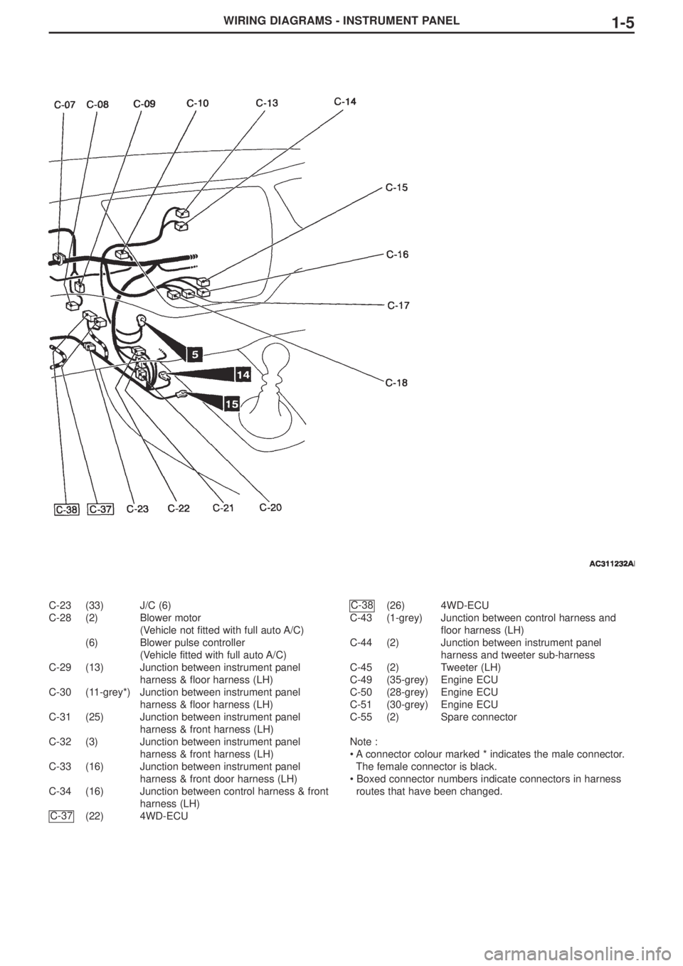
WIRING DIAGRAMS - INSTRUMENT PANEL1-5
C-23 (33) J/C (6)
C-28 (2) Blower motor
(Vehicle not fitted with full auto A/C)
(6) Blower pulse controller
(Vehicle fitted with full auto A/C)
C-29 (13) Junction between instrument panel
harness & floor harness (LH)
C-30 (11-grey*) Junction between instrument panel
harness & floor harness (LH)
C-31 (25) Junction between instrument panel
harness & front harness (LH)
C-32 (3) Junction between instrument panel
harness & front harness (LH)
C-33 (16) Junction between instrument panel
harness & front door harness (LH)
C-34 (16) Junction between control harness & front
harness (LH)
(22) 4WD-ECU(26) 4WD-ECU
C-43 (1-grey) Junction between control harness and
floor harness (LH)
C-44 (2) Junction between instrument panel
harness and tweeter sub-harness
C-45 (2) Tweeter (LH)
C-49 (35-grey) Engine ECU
C-50 (28-grey) Engine ECU
C-51 (30-grey) Engine ECU
C-55 (2) Spare connector
Note :
• A connector colour marked * indicates the male connector.
The female connector is black.
• Boxed connector numbers indicate connectors in harness
routes that have been changed.C-38
C-37
Page 105 of 166
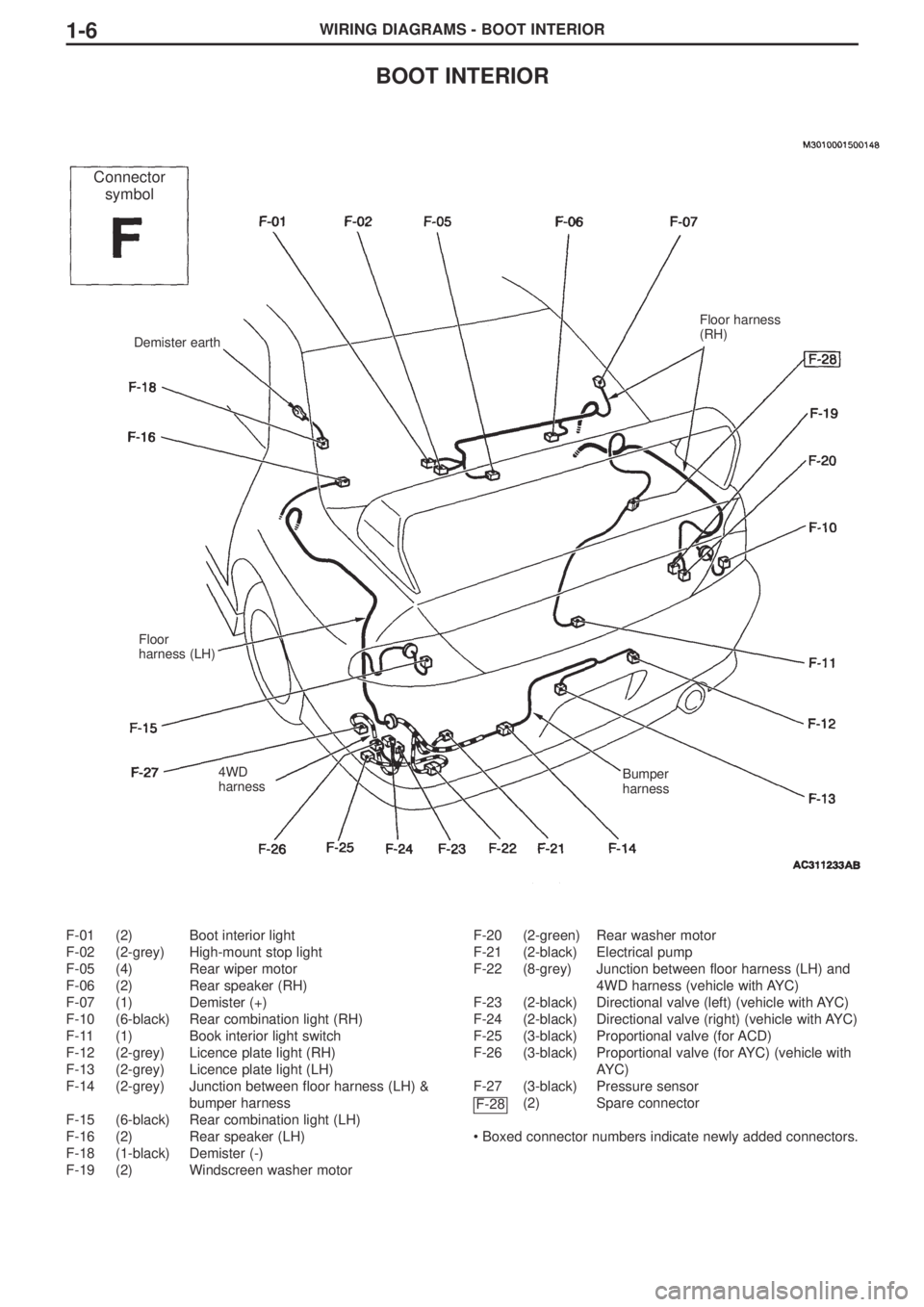
WIRING DIAGRAMS - BOOT INTERIOR1-6
BOOT INTERIOR
F-01 (2) Boot interior light
F-02 (2-grey) High-mount stop light
F-05 (4) Rear wiper motor
F-06 (2) Rear speaker (RH)
F-07 (1) Demister (+)
F-10 (6-black) Rear combination light (RH)
F-11 (1) Book interior light switch
F-12 (2-grey) Licence plate light (RH)
F-13 (2-grey) Licence plate light (LH)
F-14 (2-grey) Junction between floor harness (LH) &
bumper harness
F-15 (6-black) Rear combination light (LH)
F-16 (2) Rear speaker (LH)
F-18 (1-black) Demister (-)
F-19 (2) Windscreen washer motorF-20 (2-green) Rear washer motor
F-21 (2-black) Electrical pump
F-22 (8-grey) Junction between floor harness (LH) and
4WD harness (vehicle with AYC)
F-23 (2-black) Directional valve (left) (vehicle with AYC)
F-24 (2-black) Directional valve (right) (vehicle with AYC)
F-25 (3-black) Proportional valve (for ACD)
F-26 (3-black) Proportional valve (for AYC) (vehicle with
AYC)
F-27 (3-black) Pressure sensor
(2) Spare connector
• Boxed connector numbers indicate newly added connectors.
F-28
Demister earth
Floor
harness (LH)
4WD
harnessBumper
harness
Floor harness
(RH)
Connector
symbol
Page 108 of 166
3-1
SECTION 3
CIRCUIT DIAGRAMS
CONTENTS
J/C ............................................................3-2
Central Junction .....................................3-8
Power Supply ........................................3-10
Engine Control ......................................3-16
Signalling
Stop lights ........................................................3-24
Air Conditioning
Manual A/C ......................................................3-26
Special Equipment
ABS ..................................................................3-32
ACD (vehicle without AYC) ..............................3-40
ACD, AYC ........................................................3-48
Engine immobiliser system ..............................3-58
Page 109 of 166
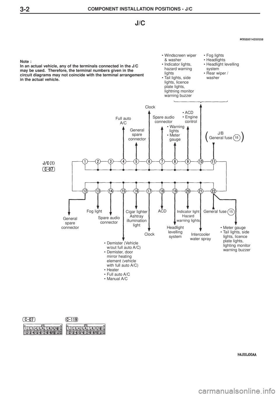
COMPONENT INSTALLATION POSITIONS - J/C3-2
J/C
Note :
In an actual vehicle, any of the terminals connected in the J/C
may be used. Therefore, the terminal numbers given in the
circuit diagrams may not coincide with the terminal arrangement
in the actual vehicle.
• Windscreen wiper
& washer
• Indicator lights,
hazard warning
lights
• Tail lights, side
lights, licence
plate lights,
lightning monitor
warning buzzer• Fog lights
• Headlights
• Headlight levelling
system
• Rear wiper /
washer
Full auto
A/C
General
spare
connector
Clock
Spare audio
connector
• Warning
lights
• Meter
gauge
• ACD
• Engine
control
J/B
General fuse
()18
General
spare
connector
Fog light
Spare audio
connector
• Demister (Vehicle
w/out full auto A/C)
• Demister, door
mirror heating
element (vehicle
with full auto A/C)
• Heater
• Full auto A/C
• Manual A/C
Cigar lighter
Ashtray
illumination
light
Clock
ACD
Headlight
levelling
system
Indicator light
Hazard
warning lights
Intercooler
water spray
General fuse15
• Meter gauge
• Tail lights, side
lights, licence
plate lights,
lighting monitor
warning buzzer
Page 111 of 166
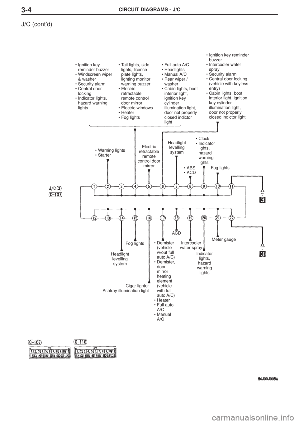
CIRCUIT DIAGRAMS - J/C3-4
J/C (cont’d)
•Ignition key
reminder buzzer
•Windscreen wiper
& washer
•Security alarm
•Central door
locking
•Indicator lights,
hazard warning
lights•Tail lights, side
lights, licence
plate lights,
lighting monitor
warning buzzer
•Electric
retractable
remote control
door mirror
•Electric windows
•Heater
•Fog lights•Full auto A/C
•Headlights
•Manual A/C
•Rear wiper /
washer
•Cabin lights, boot
interior light,
ignition key
cylinder
illumination light,
door not properly
closed indictor
light
•Ignition key reminder
buzzer
•Intercooler water
spray
•Security alarm
•Central door locking
(vehicle with keyless
entry)
•Cabin lights, boot
interior light, ignition
key cylinder
illumination light,
door not properly
closed indictor light
Fog lights
•Clock
•Indicator
lights,
hazard
warning
lights
•ABS
•ACD
Headlight
levelling
systemElectric
retractable
remote
control door
mirror•Warning lights
•Starter
Headlight
levelling
system
Fog lights
Cigar lighter
Ashtray illumination light
•Demister
(vehicle
w/out full
auto A/C)
•Demister,
door
mirror
heating
element
(vehicle
with full
auto A/C)
•Heater
•Full auto
A/C
•Manual
A/C
ACD
Intercooler
water spray
Indicator
lights,
hazard
warning
lights
Meter gauge
Page 112 of 166
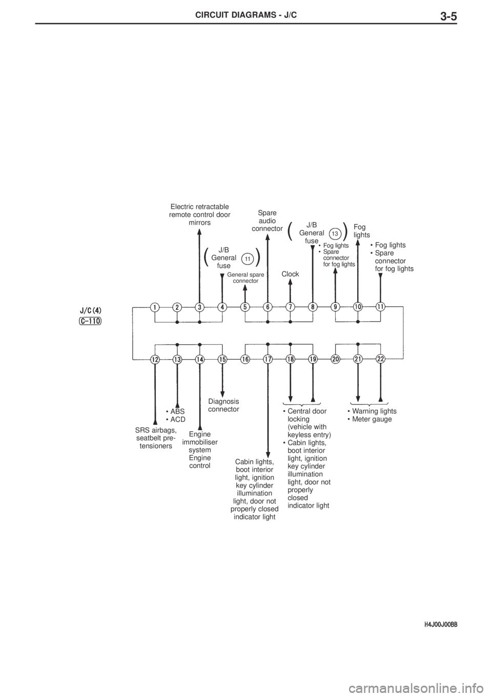
CIRCUIT DIAGRAMS - J/C3-5
Electric retractable
remote control door
mirrors
J/B
General
fuse
()11
J/B
General
fuse
()13
General spare
connector
Spare
audio
connector
Clock
•Fog lights
•Spare
connector
for fog lights
Fog
lights
•Fog lights
•Spare
connector
for fog lights
SRS airbags,
seatbelt pre-
tensioners
•ABS
•ACD
Engine
immobiliser
system
Engine
control
Diagnosis
connector
Cabin lights,
boot interior
light, ignition
key cylinder
illumination
light, door not
properly closed
indicator light
•Central door
locking
(vehicle with
keyless entry)
•Cabin lights,
boot interior
light, ignition
key cylinder
illumination
light, door not
properly
closed
indicator light•Warning lights
•Meter gauge
Page 113 of 166
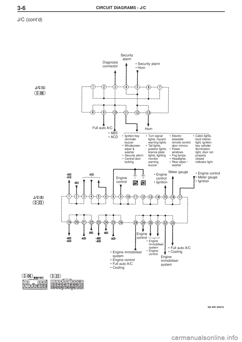
CIRCUIT DIAGRAMS - J/C3-6
J/C (cont’d)
Diagnosis
connector
Security
alarm
•Security alarm
•Horn
Full auto A/C
•ABS
•ACD
Horn
•Ignition key
reminder
buzzer
•Windscreen
wiper &
washer
•Security alarm
•Central door
locking•Turn signal
lights, hazard
warning lights
•Tail lights,
position lights,
licence plate
lights, lighting
monitor
warning
buzzer•Electric
stowable
remote control
door mirrors
•Power
windows
•Fog lamps
•Headlights
•Rear wiper /
washer•Cabin lights,
boot interior
light, ignition
key cylinder
illumination
light, door not
properly
closed
indicator light
Engine
control•Engine
control
•IgnitionMeter gauge•Engine control
•Meter gauge
•Ignition
•Engine immobiliser
system
•Engine control
•Full auto A/C
•Cooling
Engine
control
•Engine
immobiliser
system
•Engine
control
•Full auto A/C
•Cooling
Engine
immobiliser
system
Page 114 of 166

CIRCUIT DIAGRAMS3-7
(Notes)