service MITSUBISHI LANCER EVOLUTION X 2008 User Guide
[x] Cancel search | Manufacturer: MITSUBISHI, Model Year: 2008, Model line: LANCER EVOLUTION X, Model: MITSUBISHI LANCER EVOLUTION X 2008Pages: 241, PDF Size: 8.26 MB
Page 173 of 241
TRIMS
TSB Revision
INTERIOR52A-12
REMOVAL SERVICE POINT
.
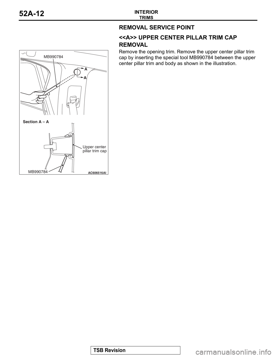
<> UPPER CENTER PILLAR TRIM CAP
REMOVAL
Remove the opening trim. Remove the upper center pillar trim
cap by inserting the special tool MB990784 between the upper
center pillar trim and body as shown in the illustration.
AC606516
A
A
MB990784
AIMB990784
Section A – A
Upper center
pillar trim cap
Page 177 of 241

HEADLINING
TSB Revision
INTERIOR52A-16
Required Special Tool:
•MB990784: Ornament Remover
REMOVAL SERVICE POINTS
.
<> SUN VISOR HOLDER REMOVAL
Insert the special tool MB990784 into side claws of the sun
visor holder through the both sides of the sun visor holder to
remove the hinges.
.
<> HEADLINING ASSEMBLY REMOVAL
To remove the clip, insert a vinyl cord into a clearance between
the clip and the headlining, and pass it around the clip. Then,
pull out the clip downwards while pulling the vinyl cord.
Removal steps
1.Assist grip
2.Rear dome light assembly
3.Front dome light
4.Sun visor assembly
<>5.Sun visor holder
6.Sunroof lid inner weather strip rear
<>7.Headlining
8.Assist grip bracket
9.Front side roof energy absorption box
10.Rear side roof energy absorption box
Removal steps (Continued)
AC005512
MB990784
MB990784
Sun visor holder
AF
AC600751AD
Clip
Headlining Vinyl cord
Page 178 of 241
INSIDE REAR VIEW MIRROR
TSB Revision
INTERIOR52A-17
INSIDE REAR VIEW MIRRORM1521002600561
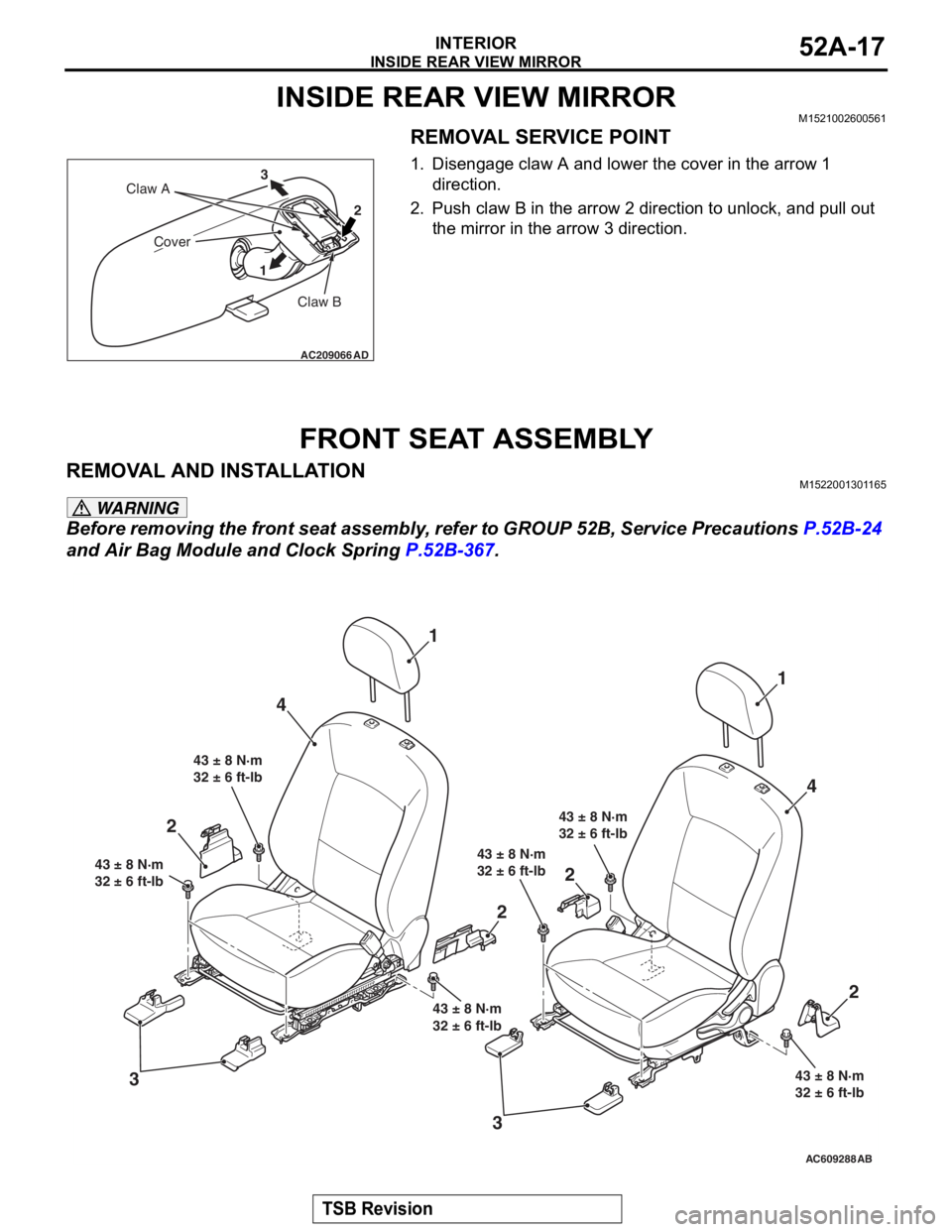
REMOVAL SERVICE POINT
1. Disengage claw A and lower the cover in the arrow 1 direction.
2. Push claw B in the arrow 2 direction to unlock, and pull out the mirror in the arrow 3 direction.
FRONT SEAT ASSEMBLY
REMOVAL AND INSTALLATIONM1522001301165
WARNING
Before removing the front seat assembly, refer to GROUP 52B, Service Precautions P.52B-24
and Air Bag Module and Clock Spring P.52B-367.
AC209066
Claw B
Claw A
Cover
12
3
AD
AC609288AB
4
3 1
43 ± 8 N·m
32 ± 6 ft-lb
43 ± 8 N·m
32 ± 6 ft-lb
43 ± 8 N·m
32 ± 6 ft-lb
43 ± 8 N·m
32 ± 6 ft-lb 43 ± 8 N·m
32 ± 6 ft-lb
43 ± 8 N·m
32 ± 6 ft-lb
1
4
2
2
2
3
2
Page 179 of 241
FRONT SEAT ASSEMBLY
TSB Revision
INTERIOR52A-18
REMOVAL SERVICE POINT
.
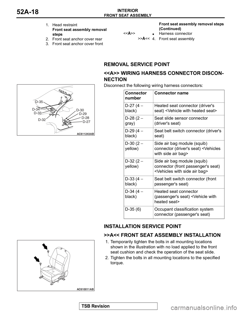
<> WIRING HARNESS CONNECTOR DISCON-
NECTION
Disconnect the following wiring harness connectors:
INSTALLATION SERVICE POINT
.
>>A<< FRONT SEAT ASSEMBLY INSTALLATION
1.Temporarily tighten the bolts in all mounting locations
shown in the illustration with no load applied to the front
seat cushion and check the operation of the seat slide.
2. Tighten the bolts in all mounti ng locations to the specified
torque.
1.Head restraint
Front seat assembly removal
steps
2.Front seat anchor cover rear
3.Front seat anchor cover front
<>•Harness connector
>>A<<4.Front seat assembly
Front seat assembly removal steps
(Continued)
Connector
numberConnector name
D-27 (4 −
black)Heated seat connector (driver's
seat)
D-28 (2 −
gray)Seat slide sensor connector
(driver's seat)
D-29 (4 −
black)Seat belt switch connector (driver's
seat)
D-30 (2 −
yellow)Side air bag module (squib)
connector (driver's seat)
D-32 (2 −
yellow)Side air bag module (squib)
connector (front passenger's seat)
D-33 (4 −
black)Seat belt switch connector (front
passenger's seat)
D-34 (4 −
black)Heated seat connector
(passenger's seat)
D-35 (6)Occupant classification system
connector (passenger's seat)
AC611243
D-30 D-29
D-28D-27
AB
D-32
D-33
D-34 D-35
AC610011AB
Page 183 of 241
FRONT SEAT ASSEMBLY
TSB Revision
INTERIOR52A-22
REMOVAL SERVICE POINT
.
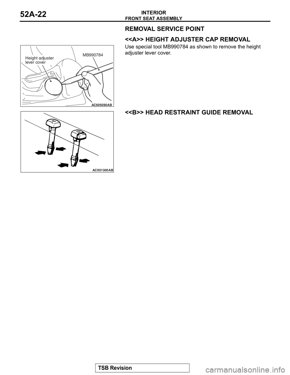
<> HEIGHT ADJUSTER CAP REMOVAL
Use special tool MB990784 as shown to remove the height
adjuster lever cover.
.
<> HEAD RESTRAINT GUIDE REMOVAL
AC609290
MB990784
AB
Height adjuster
lever cover
ACX01300AB
Page 186 of 241
REAR SEAT ASSEMBLY
TSB Revision
INTERIOR52A-25
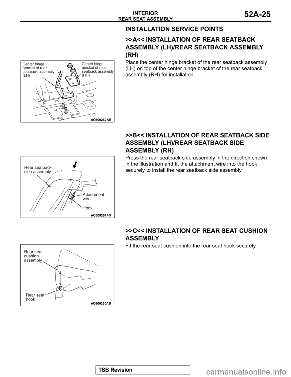
INSTALLATION SERVICE POINTS
.
>>A<< INSTALLATION OF REAR SEATBACK
ASSEMBLY (LH)/REAR SEATBACK ASSEMBLY
(RH)
Place the center hinge bracket of the rear seatback assembly
(LH) on top of the center hinge bracket of the rear seatback
assembly (RH) for installation.
.
>>B<< INSTALLATION OF REAR SEATBACK SIDE
ASSEMBLY (LH)/RE AR SEATBACK SIDE
ASSEMBLY (RH)
Press the rear seatback side as sembly in the direction shown
in the illustration and fit the attachment wire into the hook
securely to install the rear seatback side assembly.
.
>>C<< INSTALLATION OF REAR SEAT CUSHION
ASSEMBLY
Fit the rear seat cushion into the rear seat hook securely.
AC609262
Center hinge
bracket of rear
seatback assembly
(RH)
Center hinge
bracket of rear
seatback assembly
(LH)
AB
AC609261
AB
Hook
Rear seatback
side assembly
Attachment
wire
AC609260AB
Rear seat
hook
Rear seat
cushion
assembly
Page 190 of 241
FRONT SEAT BELT
TSB Revision
INTERIOR52A-29
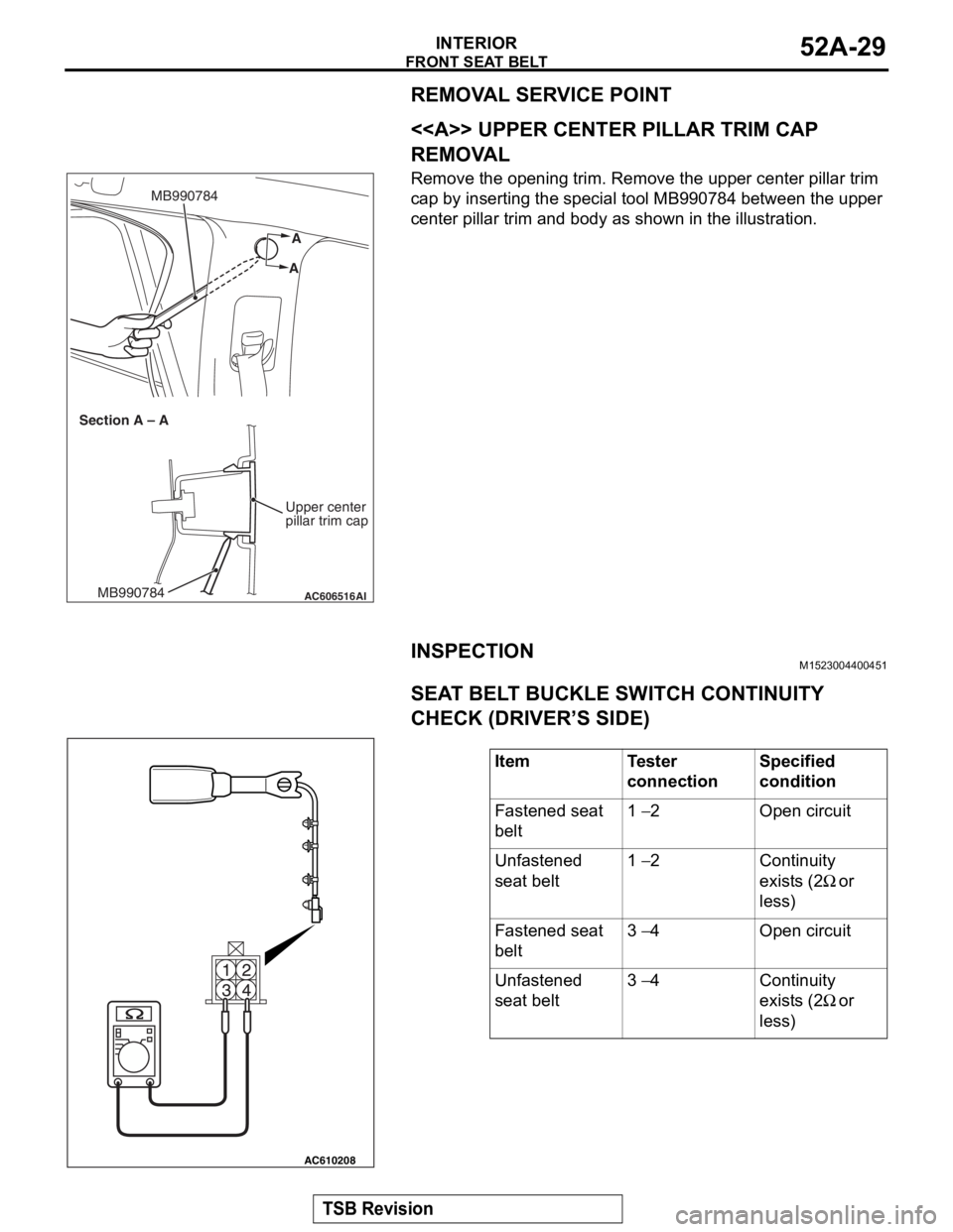
REMOVAL SERVICE POINT
.
<> UPPER CENTER PILLAR TRIM CAP
REMOVAL
Remove the opening trim. Remove the upper center pillar trim
cap by inserting the special tool MB990784 between the upper
center pillar trim and body as shown in the illustration.
INSPECTIONM1523004400451.
SEAT BELT BUCKLE SWITCH CONTINUITY
CHECK (DRIVER’S SIDE)
AC606516
A
A
MB990784
AIMB990784
Section A – A
Upper center
pillar trim cap
ItemTester
connectionSpecified
condition
Fastened seat
belt1 − 2Open circuit
Unfastened
seat belt1 − 2Continuity
exists (2
Ω or
less)
Fastened seat
belt3 − 4Open circuit
Unfastened
seat belt3 − 4Continuity
exists (2
Ω or
less)
AC610208
Page 201 of 241

GENERAL
BASIC BRAKE SYSTEM35A-2
GENERALM2350000100956
Brake systems with higher reliability and durability
have achieved distinguished braking performance.
FEATURES
.
IMPROVEMENT OF BRAKING PERFOR-
MANCE
•A 10-inch single brake booster with the variable
boost ratio mechanism has been used to assure
maximum braking force with less pedal pressure
in case of emergency.
•In addition to the 10-inch single brake booster, a
small and long stroke-type master cylinder has
been adopted to achieve downsizing and secure
assist force.
•15-inch or 16-inch ventilated disc brakes have
been adopted for the front.
•8-inch leading trailing-type drum brake, 14-inch
or 16-inch solid disc brake has been adopted for
the rear.
.
IMPROVEMENT IN SAFETY
•The 4-wheel anti-lock brake system (4ABS) has
been installed to prevent slippage resulting from
the wheel lock and assure stable vehicle posture
and driveability.
•A rear wheel early lock-prevention proportioning
valve has been used.
•Electronic control braking force distribution sys-
tem (EBD) has been adopted to assure the maxi-
mum braking force independently of the
passenger's position in the vehicle.
•X-type piping of brake lines have been adopted
for the front and rear wheels.
•Audible wear indicators are used on the front and
rear brake pads to warn the driver of wear limit.
.
SERVICE QUALITY IMPROVEMENTS
•Diagnostic function has been adopted to ABS for
easier inspection.
•Brake fluid reservoir, master cylinder, and brake
booster have been integrated for downsizing and
better serviceability.
Page 207 of 241
CONSTRUCTION DESCRIPTION
BASIC BRAKE SYSTEM35A-8
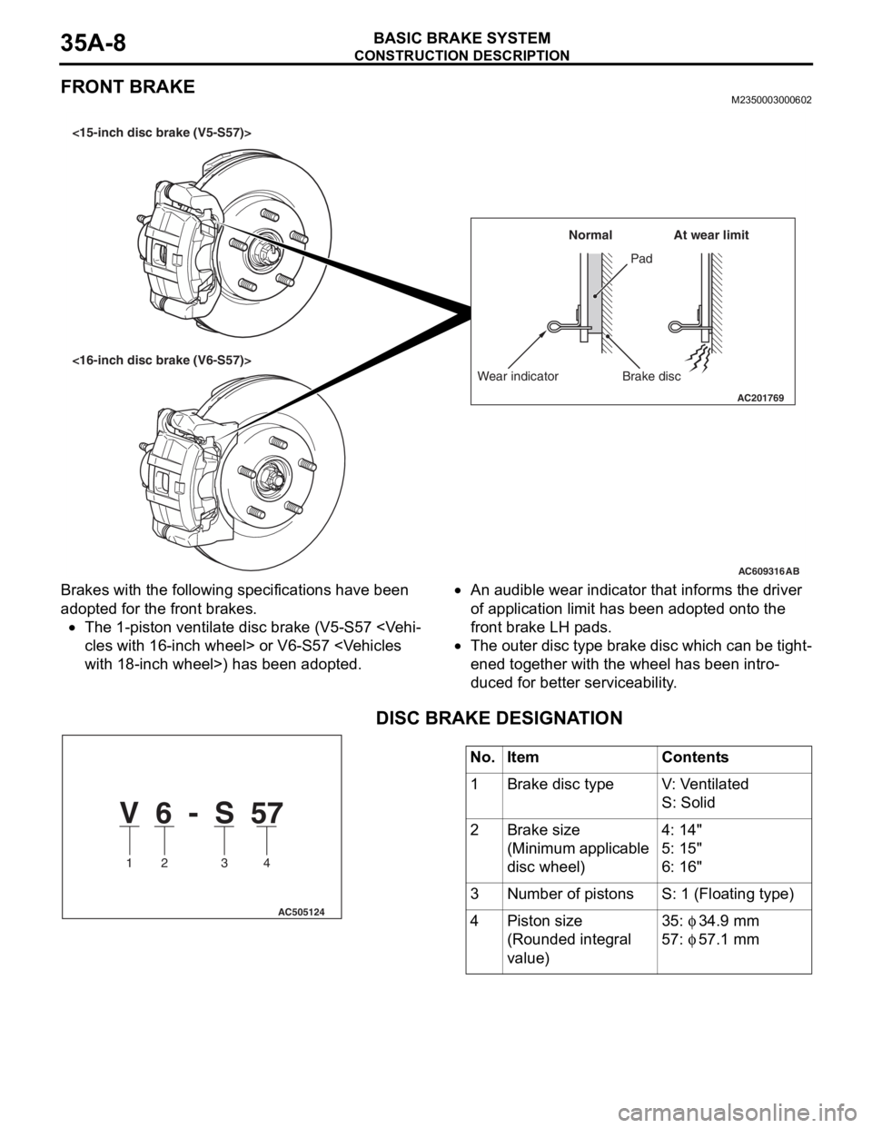
FRONT BRAKEM2350003000602
Brakes with the following specifications have been
adopted for the front brakes.
•The 1-piston ventilate disc brake (V5-S57
•An audible wear indicator that informs the driver
of application limit has been adopted onto the
front brake LH pads.
•The outer disc type brake disc which can be tight-
ened together with the wheel has been intro-
duced for better serviceability.
.
DISC BRAKE DESIGNATION
AC609316
AC201769
Wear indicator Brake discPad Normal
AB
At wear limit
<15-inch disc brake (V5-S57)>
<16-inch disc brake (V6-S57)>
No.ItemContents
1Brake disc typeV: Ventilated
S: Solid
2Brake size
(Minimum applicable
disc wheel)
4: 14"
5: 15"
6: 16"
3Number of pistonsS: 1 (Floating type)
4Piston size
(Rounded integral
value)
35: φ 34.9 mm
57: φ 57.1 mm
V 6 - S 57
1 2 3 4
AC505124
Page 208 of 241
CONSTRUCTION DESCRIPTION
BASIC BRAKE SYSTEM35A-9
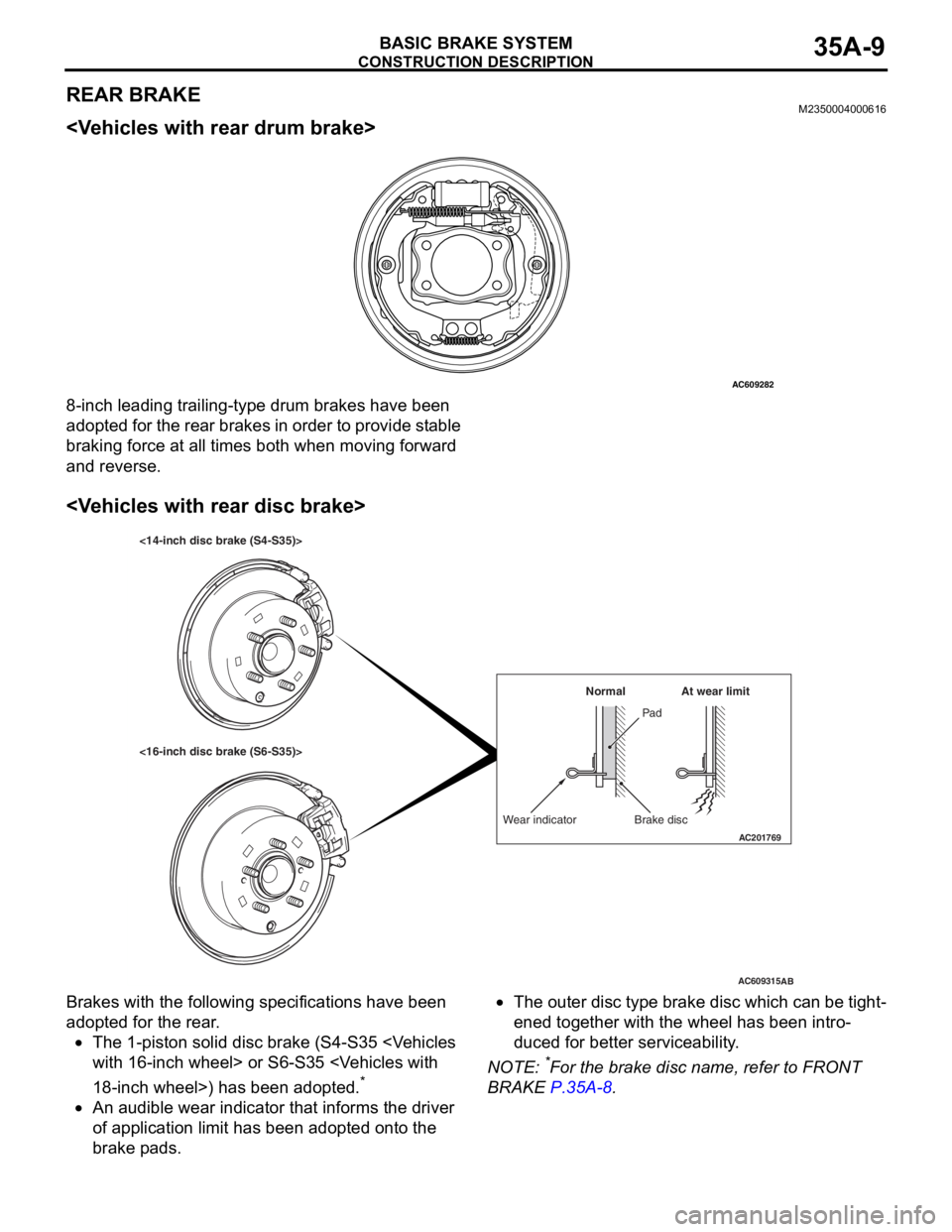
REAR BRAKEM2350004000616
8-inch leading trailing-type drum brakes have been
adopted for the rear brakes in order to provide stable
braking force at all times both when moving forward
and reverse.
Brakes with the following specifications have been
adopted for the rear.
•The 1-piston solid disc brake (S4-S35
*
•An audible wear indicator that informs the driver
of application limit has been adopted onto the
brake pads.
•The outer disc type brake disc which can be tight-
ened together with the wheel has been intro-
duced for better serviceability.
NOTE: *For the brake disc name, refer to FRONT
BRAKE
P.35A-8.
AC609282
AC609315
AC201769
Wear indicator Brake discPad Normal
AB
At wear limit
<16-inch disc brake (S6-S35)> <14-inch disc brake (S4-S35)>