ECU MITSUBISHI LANCER EVOLUTION X 2008 Owner's Manual
[x] Cancel search | Manufacturer: MITSUBISHI, Model Year: 2008, Model line: LANCER EVOLUTION X, Model: MITSUBISHI LANCER EVOLUTION X 2008Pages: 241, PDF Size: 8.26 MB
Page 50 of 241
BASE ENGINE
ENGINE MECHANICAL11A-6
PISTONS
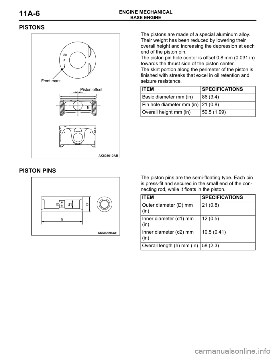
The pistons are made of a special aluminum alloy.
Their weight has been reduced by lowering their
overall height and increasing the depression at each
end of the piston pin.
The piston pin hole center is offset 0.8 mm (0.031 in)
towards the thrust side of the piston center.
The skirt portion along the perimeter of the piston is
finished with streaks that excel in oil retention and
seizure resistance.
PISTON PINS
The piston pins are the semi-floating type. Each pin
is press-fit and secured in the small end of the con
-
necting rod, while it floats in the piston.
20
A
AK603610
Front mark
Piston offset
AB
ITEMSPECIFICATIONS
Basic diameter mm (in)86 (3.4)
Pin hole diameter mm (in)21 (0.8)
Overall height mm (in)50.5 (1.99)
AK502996AE
D
hd1d2
ITEMSPECIFICATIONS
Outer diameter (D) mm
(in)21 (0.8)
Inner diameter (d1) mm
(in)12 (0.5)
Inner diameter (d2) mm
(in)10.5 (0.41)
Overall length (h) mm (in)58 (2.3)
Page 60 of 241
BASE ENGINE
ENGINE MECHANICAL11A-16
ENGINE OIL CONTROL VALVE
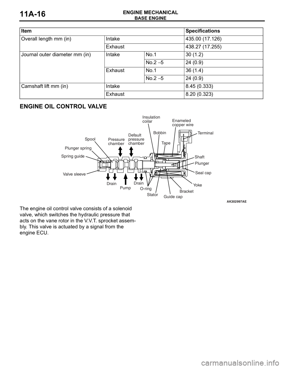
The engine oil control valve consists of a solenoid
valve, which switches the hydraulic pressure that
acts on the vane rotor in the V.V.T. sprocket assem
-
bly. This valve is actuated by a signal from the
engine ECU.
ItemSpecifications
Overall length mm (in)Intake435.00 (17.126)
Exhaust438.27 (17.255)
Journal outer diameter mm (in)IntakeNo.130 (1.2)
No.2 − 524 (0.9)
ExhaustNo.136 (1.4)
No.2 − 524 (0.9)
Camshaft lift mm (in)Intake8.45 (0.333)
Exhaust8.20 (0.323)
AK302997AE
Spring guide
Valve sleevePlunger springSpool
O-ringInsulation
coilar
Stator
Guide capBracketYo k eSeal cap Plunger ShaftTerminal Bobbin
TapeEnameled
copper wire
Drain
Drain
Pump Pressure
chamberDefault
pressure
chamber
Page 116 of 241
ACTUATOR
MULTIPORT FUEL SYSTEM (MFI)13A-23
ACTUATORM2132002000353
INJECTOR
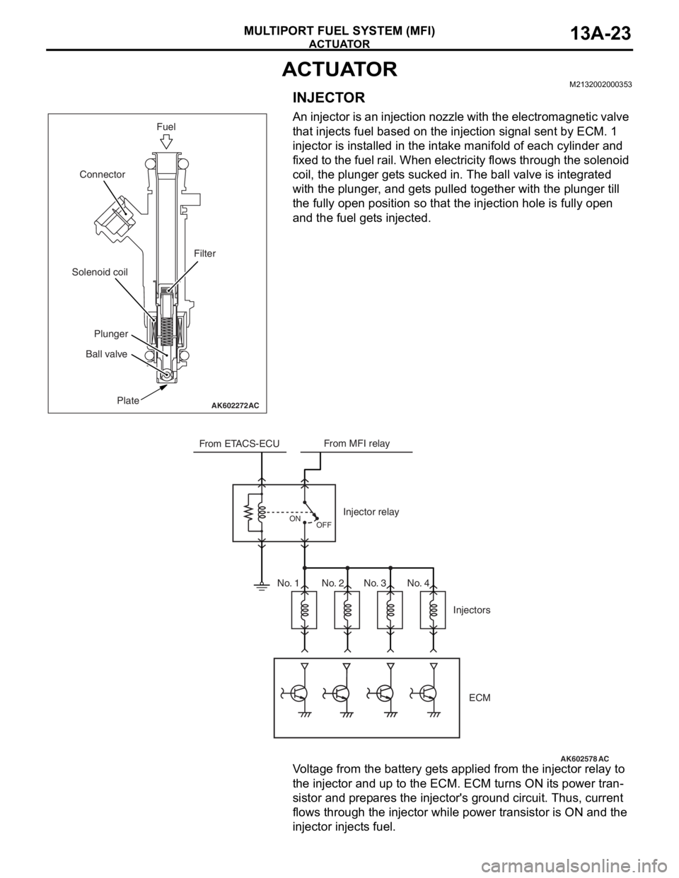
An injector is an injection nozzle with the electromagnetic valve
that injects fuel based on the injection signal sent by ECM. 1
injector is installed in the intake manifold of each cylinder and
fixed to the fuel rail. When electricity flows through the solenoid
coil, the plunger gets sucked in. The ball valve is integrated
with the plunger, and gets pulled together with the plunger till
the fully open position so that the injection hole is fully open
and the fuel gets injected.
Voltage from the battery gets applied from the injector relay to
the injector and up to the ECM. ECM turns ON its power tran
-
sistor and prepares the injector's ground circuit. Thus, current
flows through the injector while power transistor is ON and the
injector injects fuel.
AK602272AC
Fuel
Plate Ball valvePlunger Solenoid coilConnector
Filter
AK602578
From ETACS-ECUFrom MFI relay
Injector relay
Injectors
OFF ON
ECM
AC
No. 1 No. 2 No. 3 No. 4
Page 138 of 241
MULTIPORT FUEL INJECTION (MFI) RELAY CONTROL
MULTIPORT FUEL SYSTEM (MFI)13A-45
MULTIPORT FUEL INJECTION (MFI) RELAY CONTROLM2132006000173
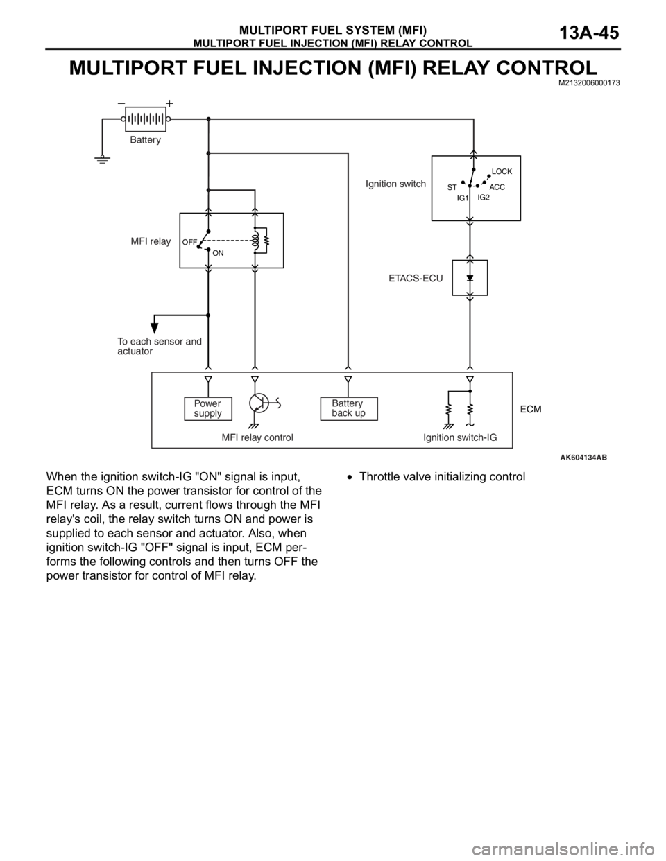
When the ignition switch-IG "ON" signal is input,
ECM turns ON the power transistor for control of the
MFI relay. As a result, current flows through the MFI
relay's coil, the relay switch turns ON and power is
supplied to each sensor and actuator. Also, when
ignition switch-IG "OFF" signal is input, ECM per
-
forms the following controls and then turns OFF the
power transistor for control of MFI relay.
•Throttle valve initializing control
AK604134AB OFF
ON
IG2 STLOCK
ACC
IG1
MFI relay
Power
supply
MFI relay control Ignition switch-IGBattery
back up To each sensor and
actuatorIgnition switch
ETACS-ECU Battery
ECM
Page 139 of 241
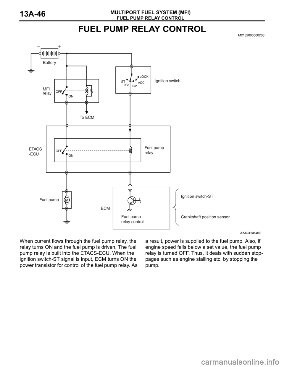
FUEL PUMP RELAY CONTROL
MULTIPORT FUEL SYSTEM (MFI)13A-46
FUEL PUMP RELAY CONTROLM2132006500208
When current flows through the fuel pump relay, the
relay turns ON and the fuel pump is driven. The fuel
pump relay is built into the ETACS-ECU. When the
ignition switch-ST signal is input, ECM turns ON the
power transistor for control of the fuel pump relay. As a result, power is supplied to the fuel pump. Also, if
engine speed falls below a set value, the fuel pump
relay is turned OFF. Thus, it deals with sudden stop
-
pages such as engine stalling etc. by stopping the
pump.
AK604135
M
OFF
ON
OFF
ON
AB IG2 STLOCK
ACC
IG1
ETACS
-ECUMFI
relay
ECM Fuel pumpFuel pump
relay
Crankshaft position sensor Ignition switch
To ECM
Ignition switch-ST Battery
Fuel pump
relay control
Page 140 of 241
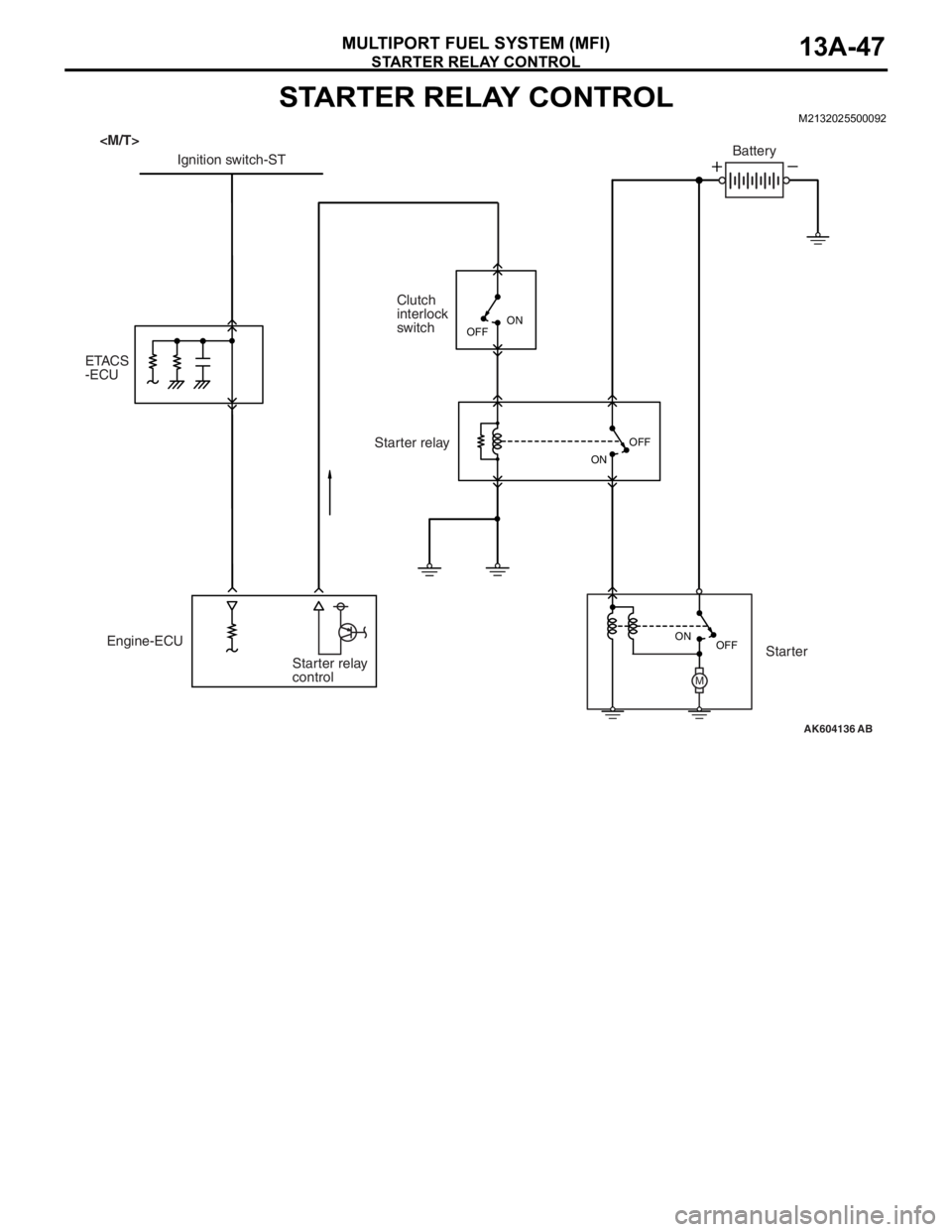
STARTER RELAY CONTROL
MULTIPORT FUEL SYSTEM (MFI)13A-47
STARTER RELAY CONTROLM2132025500092
AK604136
M
AB OFF ON OFF
ON
Engine-ECU
Starter relay
controlClutch
interlock
switch
ETACS
-ECUIgnition switch-STBattery
Starter relay
Starter
OFFON
Page 141 of 241
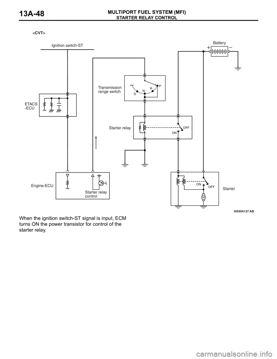
STARTER RELAY CONTROL
MULTIPORT FUEL SYSTEM (MFI)13A-48
When the ignition switch-ST signal is input, ECM
turns ON the power transistor for control of the
starter relay.
AK604137
M
AB P
DNR
OFF ON OFF
ON
Engine-ECU
Starter relay
controlTransmission
range switch Ignition switch-STBattery
Starter relay
Starter ETACS
-ECU
Page 143 of 241
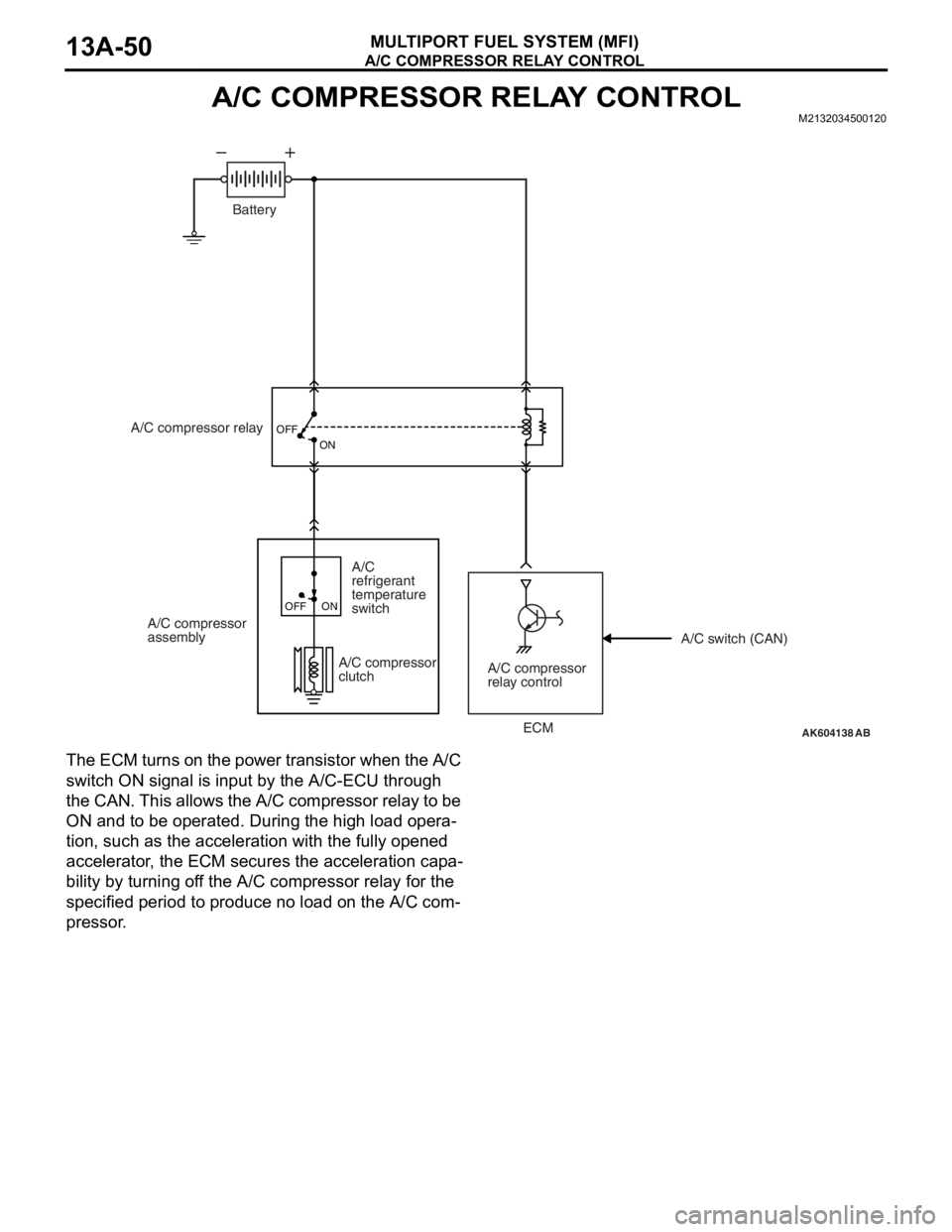
A/C COMPRESSOR RELAY CONTROL
MULTIPORT FUEL SYSTEM (MFI)13A-50
A/C COMPRESSOR RELAY CONTROLM2132034500120
The ECM turns on the power transistor when the A/C
switch ON signal is input by the A/C-ECU through
the CAN. This allows the A/C compressor relay to be
ON and to be operated. During the high load opera
-
tion, such as the acceleration with the fully opened
accelerator, the ECM secures the acceleration capa
-
bility by turning off the A/C compressor relay for the
specified period to produce no load on the A/C com
-
pressor.
AK604138
OFF
ON
AB
Battery
A/C compressor relay
A/C compressor
assembly
A/C compressor
relay control A/C compressor
clutch
A/C
refrigerant
temperature
switch
OFF ON
A/C switch (CAN)
ECM
Page 164 of 241
INSTRUMENT PANEL ASSEMBLY
TSB Revision
INTERIOR52A-3
CAUTION
•Refer to GROUP 52B-SRS Service Precautions P.52B-24 and Air bag Module and Clock Spring
P.52B-367 before removing the passenger side air bag module.
•Do not subject the SRS-ECU to any shocks when removing or installing the instrument panel.
Pre-removal and Post-installation Operation
•Removal and Installation of Front Pillar Trim (Refer to P.52A-10).
•Removal and Installation of Instrument Under Cover
(Refer to P.52A-10).
•Removal and Installation of Glove Box (Refer to P.52A-10).
•Removal and Installation of Instrument Cover Lower, Air
Outlet Garnish (Refer to P.52A-10).
•Removal and Installation of Audio Unit (Refer to GROUP
54A, Radio with CD Player P.54A-307).
•Removal and Installation of Audio Visual Navigation Unit,
GPS antenna (Refer to GROUP 54A, MMCS P.54A-391).
•Removal and Installation of Steering shaft (Refer to
GROUP 37, Steering Column Shaft P.37-25).
•Removal and Installation of Hands-free Cellular Phone
System (Refer to GROUP 54A, Hands-free Module
P.54A-435).
•Removal and Installation of Sensors (Refer to GROUP
55B, Interior Temperature Sensor
P.55B-25).
Page 186 of 241
REAR SEAT ASSEMBLY
TSB Revision
INTERIOR52A-25
INSTALLATION SERVICE POINTS
.
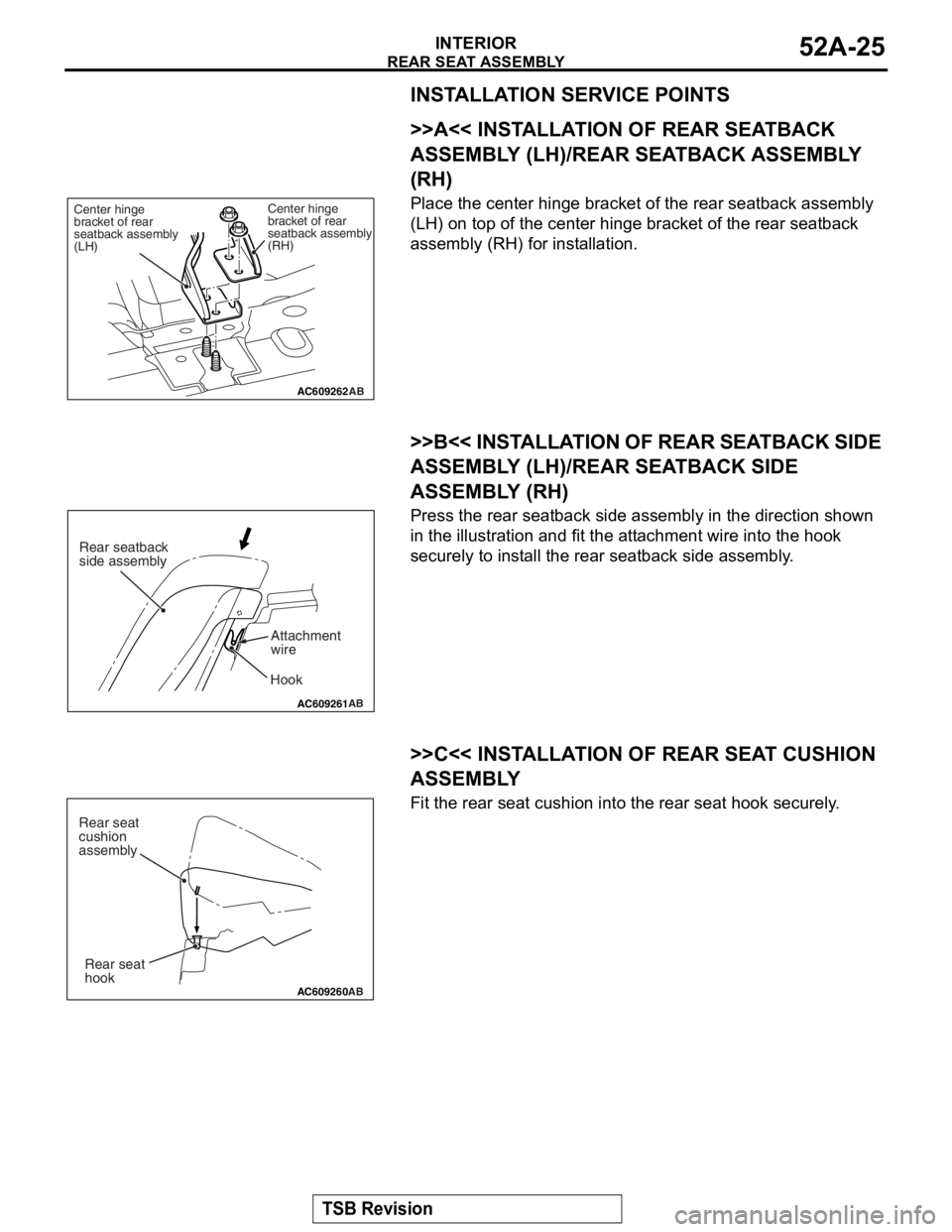
>>A<< INSTALLATION OF REAR SEATBACK
ASSEMBLY (LH)/REAR SEATBACK ASSEMBLY
(RH)
Place the center hinge bracket of the rear seatback assembly
(LH) on top of the center hinge bracket of the rear seatback
assembly (RH) for installation.
.
>>B<< INSTALLATION OF REAR SEATBACK SIDE
ASSEMBLY (LH)/RE AR SEATBACK SIDE
ASSEMBLY (RH)
Press the rear seatback side as sembly in the direction shown
in the illustration and fit the attachment wire into the hook
securely to install the rear seatback side assembly.
.
>>C<< INSTALLATION OF REAR SEAT CUSHION
ASSEMBLY
Fit the rear seat cushion into the rear seat hook securely.
AC609262
Center hinge
bracket of rear
seatback assembly
(RH)
Center hinge
bracket of rear
seatback assembly
(LH)
AB
AC609261
AB
Hook
Rear seatback
side assembly
Attachment
wire
AC609260AB
Rear seat
hook
Rear seat
cushion
assembly