belt MITSUBISHI LANCER EVOLUTION X 2008 Workshop Manual
[x] Cancel search | Manufacturer: MITSUBISHI, Model Year: 2008, Model line: LANCER EVOLUTION X, Model: MITSUBISHI LANCER EVOLUTION X 2008Pages: 241, PDF Size: 8.26 MB
Page 41 of 241
A/C COMPRESSOR
HEATER, AIR CONDITIONING AND VENTILATION55-9
A/C COMPRESSORM2551001100268
HIGH EFFICIENCY COMPRESSOR WITH
INTEGRATED OIL SEPARATOR
High efficiency compressor with integrated oil sepa-
rator has been adopted to enhance fuel economy by
reducing the A/C operating rate.
MAGNETIC CLUTCH WITH THERMAL
FUSE
At the compressor lock, the thermal fuse integrated
in the magnet clutch is blown due to the frictional
heat against the compressor in order to reduce risk
of the drive belt breakage. The thermal fuse, together
with the coil, is coated with resin to enhance resis
-
tance to corrosion.
2-STEP PROFILE COMPRESSOR
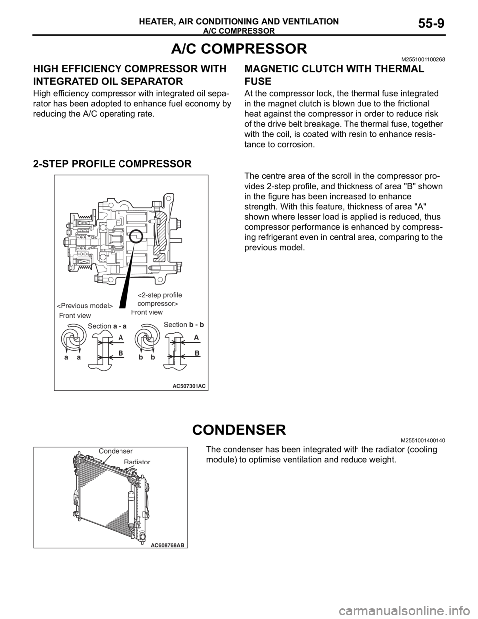
The centre area of the scroll in the compressor pro-
vides 2-step profile, and thickness of area "B" shown
in the figure has been increased to enhance
strength. With this feature, thickness of area "A"
shown where lesser load is applied is reduced, thus
compressor performance is enhanced by compress
-
ing refrigerant even in central area, comparing to the
previous model.
CONDENSERM2551001400140
The condenser has been integrated with the radiator (cooling
module) to optimise ventilation and reduce weight.
AC507301
aa bbAA
BB
AC
Section a - aSection b - b Front viewFront view
compressor>
AC608768
Condenser
AB
Radiator
Page 54 of 241
BASE ENGINE
ENGINE MECHANICAL11A-10
CRANKSHAFT PULLEY
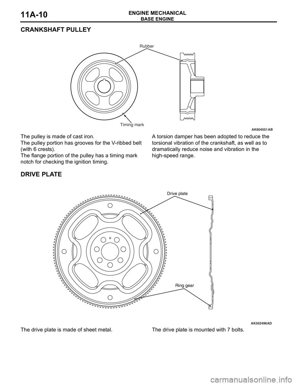
The pulley is made of cast iron.
The pulley portion has grooves for the V-ribbed belt
(with 6 crests).
The flange portion of the pulley has a timing mark
notch for checking the ignition timing.
A torsion damper has been adopted to reduce the
torsional vibration of the crankshaft, as well as to
dramatically reduce noise and vibration in the
high-speed range.
DRIVE PLATE
The drive plate is made of sheet metal.The drive plate is mounted with 7 bolts.
AK604551Timing markRubberAB
AK502496
Ring gear Drive plate
AD
Page 88 of 241

GENERAL INFORMATION
ENGINE COOLING14-2
GENERAL INFORMATIONM2140000100780
The cooling system is a water-cooled pressurized,
forced circulation type which offers the following fea
-
tures.
•To stabilize engine coolant temperature, the ther-
mostat is located at the coolant inlet port from the
radiator.
•To improve engine cooling performance and save
weight, a plastic tank and aluminum radiator fins
are used.
SPECIFICATIONS
CONSTRUCTION DIAGRAM
ItemSpecification
Cooling methodWater-cooled pressurized, forced
circulation with electrical fan
RadiatorTy p ePressurized corrugate type
Performance kJ/h (kcal/h)222,480 (53,148)
Water pumpTy p eCentrifugal impeller
Drive methodDrive belt
ThermostatTy p eWax pellet with jiggle valve
Valve open temperature °C (°F)82 (180)
AC608448
Condenser fan motor Radiator assemblyRadiator upper hose
assembly
Radiator condenser
tank assembly Radiator fan motor
Cooling fan shroud
Radiator lower hose Transmission oil
cooler line hose
and tube assembly
AB
Page 89 of 241
WATER PASSAGE
ENGINE COOLING14-3
WATER PASSAGEM2140004000172
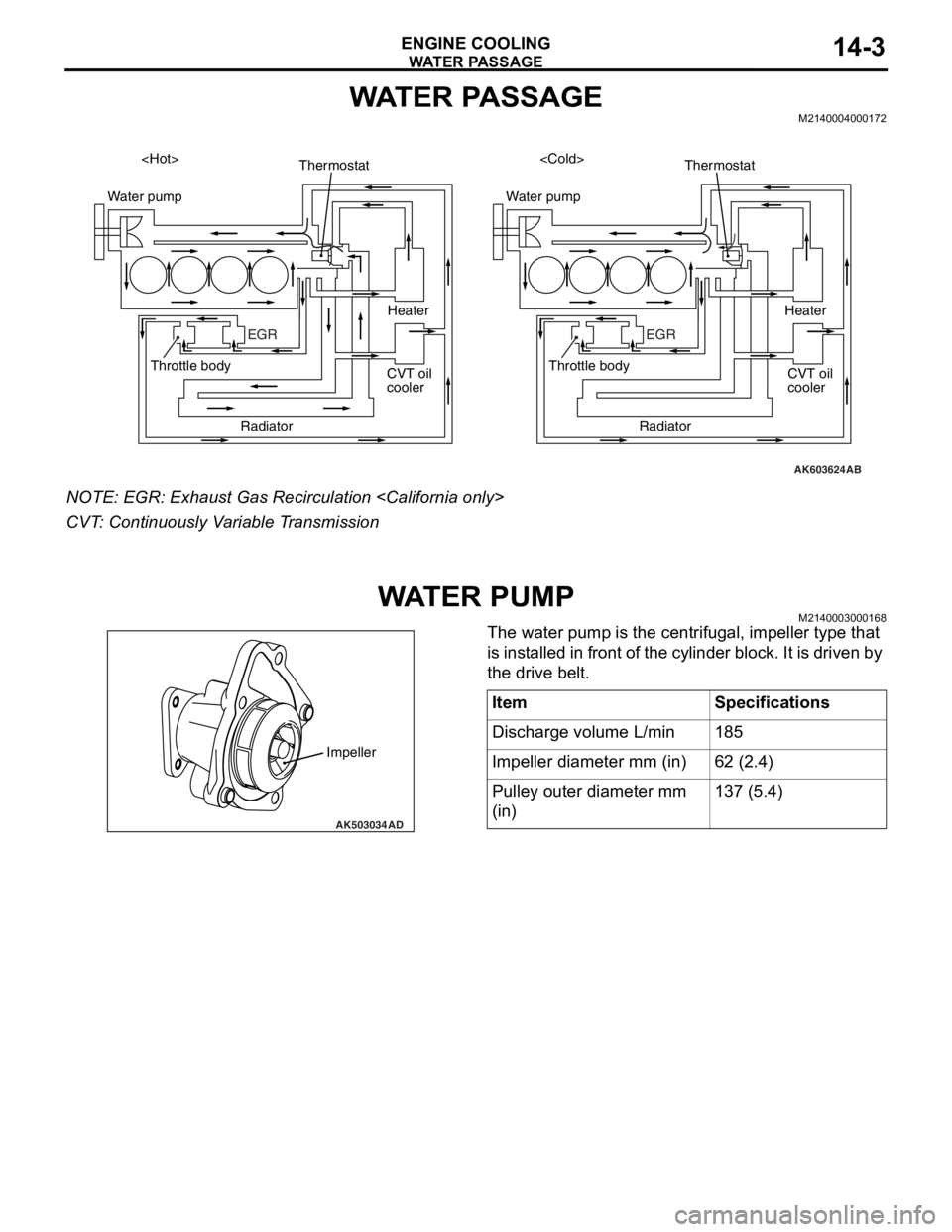
NOTE: EGR: Exhaust Gas Recirculation
CVT: Continuously Variable Transmission
WAT E R P U M PM2140003000168
The water pump is the centrifugal, impeller type that
is installed in front of the cylinder block. It is driven by
the drive belt.
AK603624
Water pump
EGR
AB
Thermostat
Radiator Throttle body
CVT oil
coolerHeater
Water pump
EGR
Thermostat
Radiator Throttle body
CVT oil
cooler Heater
AK503034
Impeller
AD
ItemSpecifications
Discharge volume L/min185
Impeller diameter mm (in)62 (2.4)
Pulley outer diameter mm
(in)137 (5.4)
Page 150 of 241
52A-1
GROUP 52A
INTERIOR
CONTENTS
GENERAL INFORMATION . . . . . . . .52A-2
INSTRUMENT PANEL AND FLOOR
CONSOLE . . . . . . . . . . . . . . . . . . . . .52A-3
SEAT . . . . . . . . . . . . . . . . . . . . . . . . .52A-5
FRONT SEAT . . . . . . . . . . . . . . . . . . . . . . . 52A-5
REAR SEAT . . . . . . . . . . . . . . . . . . . . . . . . 52A-7
SEAT BELT. . . . . . . . . . . . . . . . . . . . .52A-8
TRIMS . . . . . . . . . . . . . . . . . . . . . . . . .52A-10
INTERIOR TRIMS . . . . . . . . . . . . . . . . . . . . 52A-10
DOOR TRIM . . . . . . . . . . . . . . . . . . . . . . . . 52A-11
HEADLINING . . . . . . . . . . . . . . . . . . .52A-12
Page 151 of 241

GENERAL INFORMATION
INTERIOR52A-2
GENERAL INFORMATIONM2520000101013
Functionality, interior comfort, and safety have been
emphasized, giving interior design for elegance and
relaxation space. Various measures have been taken
to protect the environment and recycle resources.
FEATURES
Quality improvement
1. Two-tone interior
2. Full interior trim
Usability improvement
1. Armrest (floor console, rear seat, front door trim, rear door trim)
2. Cup holder (floor console, rear seat armrest)
3. Bottle holder (front door trim)
Convenient storage
1. Glove box
2. Seatback pocket (driver’s seat)
3. Card holder (glove box)
4. Tissue paper holder (floor console)
5. Floor console box
6. Door pocket (front door trim, rear door trim)
Safety improvement
1. Front and rear collision protection seat mecha-
nism (front seat)
2. ISO-FIX lower anchor (rear seat outside)
3. Upper tether anchor (rear shelf)
4. ELR 3-point seat belt (driver’s seat)
5. ELR/ALR 3-point seat belt (front passenger, rear)
6. Seat belt retractor with a driver's side preten-
sioner and force limiter
7. Seat belt retractor with a passenger’s side pre-
tensioner and force limiter
8. Headliner energy absorption rib
Consideration for the optimum driving position
1. Seat height adjustment (driver’s seat)
2. Head restraint with height adjustment (front, rear)
3. Seat slide adjustment (front)
Measures for resource recycling
1. Aggressively use PP materials that are easy to recycle and easy to stamp material symbols on
the plastic (resin) parts.
2. Reduction of chemical material (formaldehyde*,
organic solvent)
NOTE: *: Clear and colourless, toxic, irritating odour
Page 157 of 241
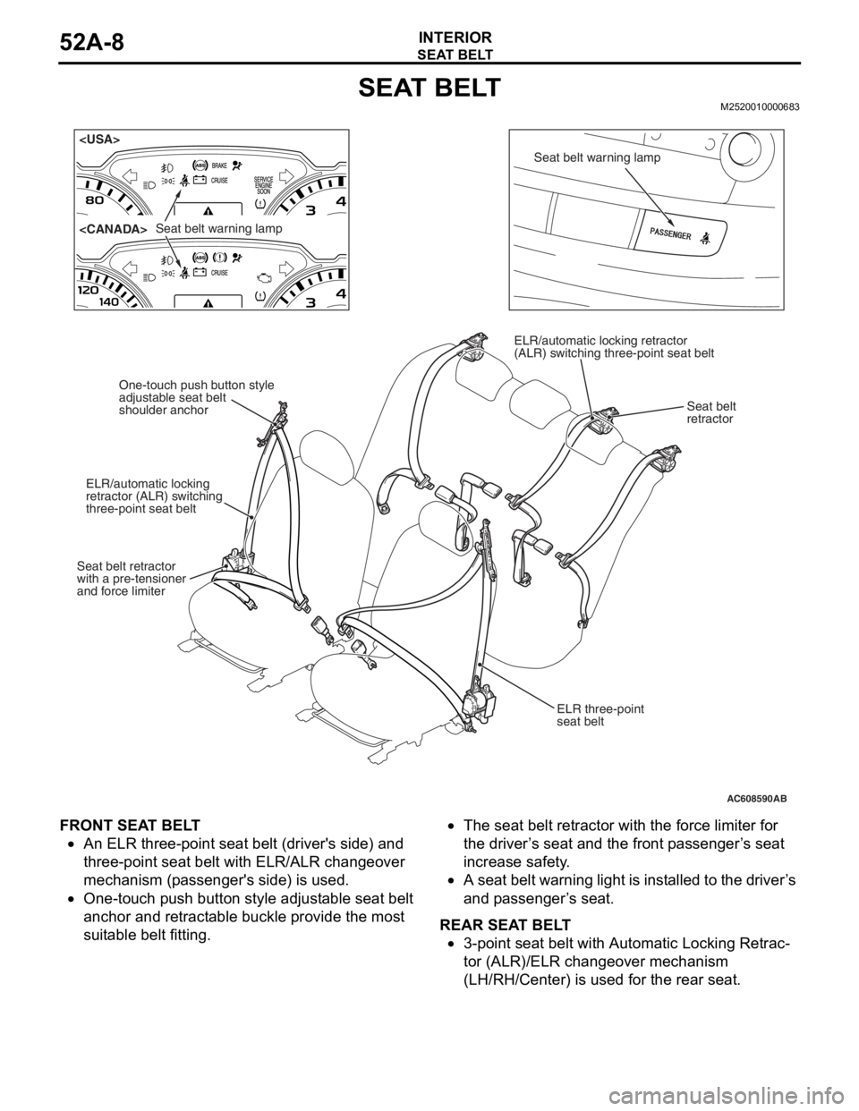
SEAT BELT
INTERIOR52A-8
SEAT BELTM2520010000683
FRONT SEAT BELT
•An ELR three-point seat belt (driver's side) and
three-point seat belt with ELR/ALR changeover
mechanism (passenger's side) is used.
•One-touch push button style adjustable seat belt
anchor and retractable buckle provide the most
suitable belt fitting.
•The seat belt retractor with the force limiter for
the driver’s seat and the front passenger’s seat
increase safety.
•A seat belt warning light is installed to the driver’s
and passenger’s seat.
REAR SEAT BELT
•3-point seat belt with Automatic Locking Retrac-
tor (ALR)/ELR changeover mechanism
(LH/RH/Center) is used for the rear seat.
AC608590
Seat belt warning lamp
Seat belt warning lamp
ELR three-point
seat belt
One-touch push button style
adjustable seat belt
shoulder anchor
ELR/automatic locking
retractor (ALR) switching
three-point seat belt
Seat belt retractor
with a pre-tensioner
and force limiter ELR/automatic locking retractor
(ALR) switching three-point seat belt
Seat belt
retractor
AB
Page 158 of 241

SEAT BELT
INTERIOR52A-9
SEAT BELT RETRACTOR WITH FORCE LIMITER
.The driver’s/front passenger’s seat belt retractor has been
equipped with a force limiter. The force limiter is a device which
operates when a predetermined force is applied, and limits the
force.
.
OPERATION
1. If a collision energy is transmi tted to the seat belt, the ELR
mechanism will operate to lock the seat belt.
2. If the energy increases to a predetermined value, the torsion bar will be distorted. As the spindle rotates together with the
torsion bar, the seat belt w ebbing is pulled out, reducing the
impact to the occupants.
AC100083
TORSION BAR
SPINDLE
BELT
AB
Page 162 of 241
52A-1
GROUP 52A
INTERIOR
CONTENTS
GENERAL DESCRIPTION. . . . . . . . .52A-2
SPECIAL TOOL . . . . . . . . . . . . . . . . .52A-2
INSTRUMENT PANEL ASSEMBLY*.52A-2
REMOVAL AND INSTALLATION . . . . . . . . 52A-2
GLOVE BOX . . . . . . . . . . . . . . . . . . .52A-5
REMOVAL AND INSTALLATION . . . . . . . . 52A-5
INSTRUMENT CENTER PANEL . . . .52A-6
REMOVAL AND INSTLLATION . . . . . . . . . 52A-6
INSTRUMENT LOWER PANEL. . . . .52A-7
REMOVAL AND INSTALLATION . . . . . . . . 52A-7
FLOOR CONSOLE ASSEMBLY . . . .52A-8
REMOVAL AND INSTALLATION . . . . . . . . 52A-8
TRIMS. . . . . . . . . . . . . . . . . . . . . . . . .52A-10
REMOVAL AND INSTALLATION . . . . . . . . 52A-10
DOOR TRIM . . . . . . . . . . . . . . . . . . . .52A-13
REMOVAL AND INSTALLATION . . . . . . . . 52A-13
HEADLINING . . . . . . . . . . . . . . . . . . .52A-15
REMOVAL AND INSTALLATION . . . . . . . . 52A-15
INSIDE REAR VIEW MIRROR . . . . . .52A-17
FRONT SEAT ASSEMBLY* . . . . . . . .52A-17
REMOVAL AND INSTALLATION . . . . . . . . 52A-17
INSPECTION. . . . . . . . . . . . . . . . . . . . . . . . 52A-19
DISASSEMBLY AND ASSEMBLY . . . . . . . 52A-21
REAR SEAT ASSEMBLY . . . . . . . . . .52A-23
REMOVAL AND INSTALLATION . . . . . . . . 52A-23
DISASSEMBLY AND ASSEMBLY . . . . . . . 52A-26
FRONT SEAT BELT* . . . . . . . . . . . . .52A-28
REMOVAL AND INSTALLATION . . . . . . . . 52A-28
INSPECTION. . . . . . . . . . . . . . . . . . . . . . . . 52A-29
REAR SEAT BELT . . . . . . . . . . . . . . .52A-31
REMOVAL AND INSTALLATION . . . . . . . . 52A-31
WARNINGS REGARDING SERVICING OF SUPPLEMENTAL RESTRAINT SYSTEM (SRS) EQUIPPED VEHICLES
WARNING
•Improper service or maintenance of an y component of the SRS, or any SRS-related component, can lead to
personal injury or death to service personnel (from inadvertent firing of the air bag) or to the driver and
passenger (from renderin g the SRS inoperative).
•Service or maintenance of any SRS component or SRS-related component must be performed only at an
authorized MITSUBISHI dealer.
•MITSUBISHI dealer personnel must thoroughly review this manual, and especially its GROUP 52B - Supplemental
Restraint System (SRS) before beginning any service or maintenance of any component of the SRS or any
SRS-related component.
NOTE
The SRS includes the following components: SRS air bag control unit, SRS warning light, front impact sensors, driver’s and
passenger’s (front) air bag modules, knee air bag module, side-airbag module, curtain air bag module, side impact sensors,
seat belt pre-tensioners, clock spring, and interconnecting wiring. Other SRS-related components (that may have to be
removed/installed in connection with SRS service or maintenance) are indicated in the table of contents by an asterisk (*).
Page 163 of 241
GENERAL DESCRIPTION
TSB Revision
INTERIOR52A-2
GENERAL DESCRIPTIONM1521000100429
OPERATION
.
SEAT BELT WARNING SYSTEM
If the driver turns the ignition switch to the "ON" posi-
tion without fastening the seat belt, the seat belt
warning light illuminates.
SPECIAL TOOLM1521000600576
INSTRUMENT PANEL ASSEMBLY
REMOVAL AND INSTALLATIONM1521001701591
WARNING
For removal and installation of the passenger's side air bag module, always observe the ser-
vice procedures described in GROUP 52B, Air Bag Module and Clock Spring P.52B-367.
The following bolts and screws are used for installing the in strument panel. Bolts and screws are indicated as
marks shown in the illustration in the sections of "R emoval and Installation" and "Disassembly and Assem
-
bly."
D: Thread diameter, L: Effective thread length
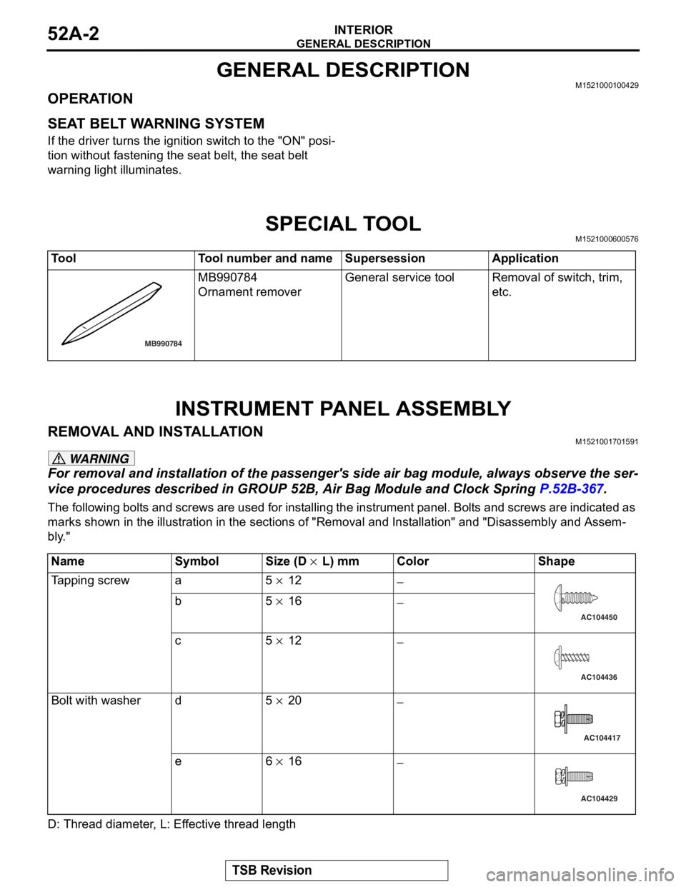
ToolTool number and nameSupersessionApplication
MB990784
Ornament remover
General service toolRemoval of switch, trim,
etc.
MB990784
NameSymbolSize (D × L) mmColorShape
Tapping screwa5 × 12−
b5 × 16−
c5 × 12−
Bolt with washerd5 × 20−
e6 × 16−
AC104450
AC104436
AC104417
AC104429