brake fluid MITSUBISHI LANCER EVOLUTION X 2008 Workshop Manual
[x] Cancel search | Manufacturer: MITSUBISHI, Model Year: 2008, Model line: LANCER EVOLUTION X, Model: MITSUBISHI LANCER EVOLUTION X 2008Pages: 241, PDF Size: 8.26 MB
Page 201 of 241

GENERAL
BASIC BRAKE SYSTEM35A-2
GENERALM2350000100956
Brake systems with higher reliability and durability
have achieved distinguished braking performance.
FEATURES
.
IMPROVEMENT OF BRAKING PERFOR-
MANCE
•A 10-inch single brake booster with the variable
boost ratio mechanism has been used to assure
maximum braking force with less pedal pressure
in case of emergency.
•In addition to the 10-inch single brake booster, a
small and long stroke-type master cylinder has
been adopted to achieve downsizing and secure
assist force.
•15-inch or 16-inch ventilated disc brakes have
been adopted for the front.
•8-inch leading trailing-type drum brake, 14-inch
or 16-inch solid disc brake has been adopted for
the rear.
.
IMPROVEMENT IN SAFETY
•The 4-wheel anti-lock brake system (4ABS) has
been installed to prevent slippage resulting from
the wheel lock and assure stable vehicle posture
and driveability.
•A rear wheel early lock-prevention proportioning
valve has been used.
•Electronic control braking force distribution sys-
tem (EBD) has been adopted to assure the maxi-
mum braking force independently of the
passenger's position in the vehicle.
•X-type piping of brake lines have been adopted
for the front and rear wheels.
•Audible wear indicators are used on the front and
rear brake pads to warn the driver of wear limit.
.
SERVICE QUALITY IMPROVEMENTS
•Diagnostic function has been adopted to ABS for
easier inspection.
•Brake fluid reservoir, master cylinder, and brake
booster have been integrated for downsizing and
better serviceability.
Page 204 of 241

CONSTRUCTION DESCRIPTION
BASIC BRAKE SYSTEM35A-5
CONSTRUCTION DESCRIPTION
MASTER CYLINDERM2350001000576
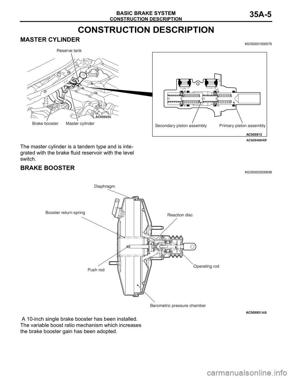
The master cylinder is a tandem type and is inte-
grated with the brake fluid reservoir with the level
switch.
BRAKE BOOSTERM2350002000698
A 10-inch single brake booster has been installed.
The variable boost ratio mechanism which increases
the brake booster gain has been adopted.
AC609255
AC609469 AC505913
AB
Primary piston assembly Secondary piston assembly Brake booster Master cylinderReserve tank
AC505931AB
Diaphragm
Reaction disc
Operating rod
Push rod
Barometric pressure chamber Booster return spring
Page 212 of 241

GENERAL INFORMATION
FOUR-WHEEL ANTI-LOCK BRAKE SYSTEM (4ABS)35B-3
MAIN COMPONENTS AND FUNCTIONS
.
Parts nameNo.Functional description
SensorWheel speed sensor1Outputs the frequency signal in proportion to the
rotation speed of each wheel to ABS-ECU.
Magnetic encoder for
wheel speed detection2The wheel speed sensor is a pulse generator. When
the magnetic encoder for wheel speed detection (a
plate on which north and south pole sides of the
magnets are arranged alternately) rotates, it outputs
frequency pulse signal in proportion to each wheel
speed.
Stop light switch3Outputs the signal indicating whether the brake pedal
is depressed or not through ETACS-ECU to ABS-ECU
via the CAN line.
ActuatorHydraulic unit4Drives the solenoid valve using the signal from
ABS-ECU, and controls the brake fluid pressure for
each wheel.
ABS warning light5Informs the driver of the system status by illuminating,
flashing, or turning off the warning light according to
the signal from ABS-ECU.
Brake warning light6Used as the warning light for the parking brake, brake
fluid level, and EBD control. Informs the driver of the
system status by illuminating or turning off the warning
light according to the signal from ABS-ECU, ETACS or
combination meter.
Data link connector7Establishes the communication with scan tool.
ABS control unit (ABS-ECU)8Controls the actuators (described above) based on the
signals coming from each sensors.
Controls the self-diagnostic functions and fail-safe
functions.
Controls diagnostic function (Compatible with scan
tool).
Page 215 of 241

CONSTRUCTION DESCRIPTION
FOUR-WHEEL ANTI-LOCK BRAKE SYSTEM (4ABS)35B-6
CONSTRUCTION DESCRIPTION
SENSORM2351001000494
Wheel speed sensor
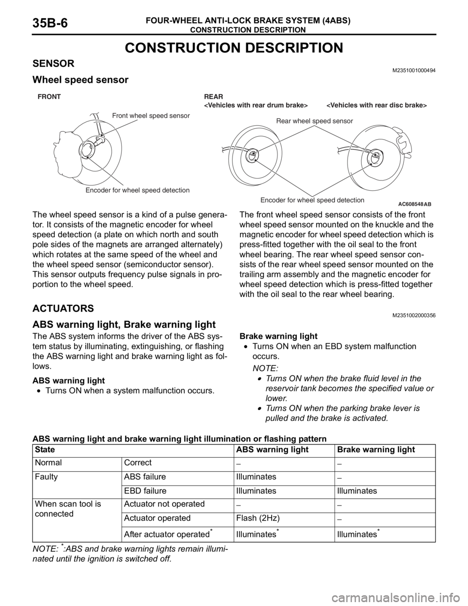
The wheel speed sensor is a kind of a pulse genera-
tor. It consists of the magnetic encoder for wheel
speed detection (a plate on which north and south
pole sides of the magnets are arranged alternately)
which rotates at the same speed of the wheel and
the wheel speed sensor (semiconductor sensor).
This sensor outputs frequency pulse signals in pro
-
portion to the wheel speed.
The front wheel speed sensor consists of the front
wheel speed sensor mounted on the knuckle and the
magnetic encoder for wheel speed detection which is
press-fitted together with the oil seal to the front
wheel bearing. The rear wheel speed sensor con
-
sists of the rear wheel speed sensor mounted on the
trailing arm assembly and the magnetic encoder for
wheel speed detection which is press-fitted together
with the oil seal to the rear wheel bearing.
ACTUATORSM2351002000356
ABS warning light, Brake warning light
The ABS system informs the driver of the ABS sys-
tem status by illuminating, extinguishing, or flashing
the ABS warning light and brake warning light as fol
-
lows.
ABS warning light
•Turns ON when a system malfunction occurs.
Brake warning light
•Turns ON when an EBD system malfunction
occurs.
NOTE: .
•Turns ON when the brake fluid level in the
reservoir tank becomes the specified value or
lower.
•Turns ON when the parking brake lever is
pulled and the brake is activated.
ABS warning light and brake warning light illumination or flashing pattern
NOTE: *:ABS and brake warning lights remain illumi-
nated until the ignition is switched off.
AC608548
AB
FRONT REAR
Front wheel speed sensor
Rear wheel speed sensor
Encoder for wheel speed detection
Encoder for wheel speed detection
StateABS warning lightBrake warning light
NormalCorrect−−
FaultyABS failureIlluminates−
EBD failureIlluminatesIlluminates
When scan tool is
connectedActuator not operated−−
Actuator operatedFlash (2Hz)−
After actuator operated*Illuminates*Illuminates*
Page 216 of 241

CONSTRUCTION DESCRIPTION
FOUR-WHEEL ANTI-LOCK BRAKE SYSTEM (4ABS)35B-7
ABS-ECUM2351003000520
•By integrating ABS-ECU into the hydraulic unit,
no wiring harness for sending drive signal of the
solenoid valve and pump motor is required,
assuring higher reliability.
•Self-diagnostic and memory functions are inte-
grated into ABS-ECU. If any malfunction is
detected by the self-diagnostic function,
ABS-ECU activates a fail-safe function and illumi
-
nates the ABS warning light and brake warning
light
*.
NOTE: *: The brake warning light is used as the
EBD control warning light.
•ABS-ECU detects vehicle speed from the signals
of the wheel speed sensor and its recognizes the
wheel rotation status, estimates the wheel slip
condition based on the preprogrammed algo
-
rithm, and then controls the solenoid valve in the
hydraulic unit so that the wheels do not lock.
ABS hydraulic pressure control
ABS control cycle
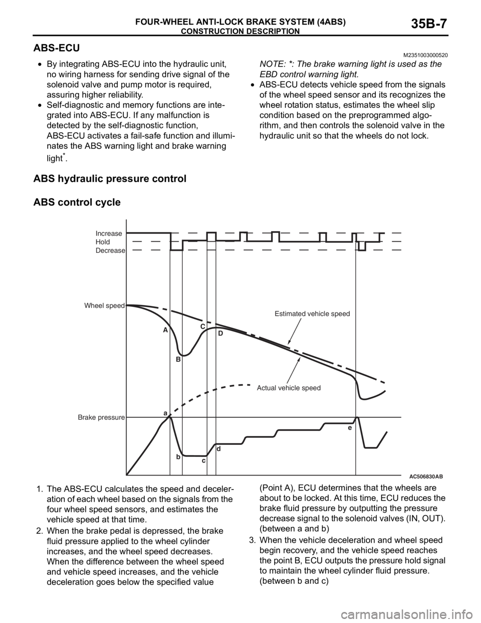
1. The ABS-ECU calculates the speed and deceler-
ation of each wheel based on the signals from the
four wheel speed sensors, and estimates the
vehicle speed at that time.
2. When the brake pedal is depressed, the brake
fluid pressure applied to the wheel cylinder
increases, and the wheel speed decreases.
When the difference between the wheel speed
and vehicle speed increases, and the vehicle
deceleration goes below the specified value (Point A), ECU determines that the wheels are
about to be locked. At this time, ECU reduces the
brake fluid pressure by outputting the pressure
decrease signal to the solenoid valves (IN, OUT).
(between a and b)
3. When the vehicle deceleration and wheel speed
begin recovery, and the vehicle speed reaches
the point B, ECU outputs the pressure hold signal
to maintain the wheel cylinder fluid pressure.
(between b and c)
AC506830AB
a
b
cd A
BC
D
e Increase
Hold
Decrease
Wheel speed
Brake pressureActual vehicle speedEstimated vehicle speed
Page 217 of 241

CONSTRUCTION DESCRIPTION
FOUR-WHEEL ANTI-LOCK BRAKE SYSTEM (4ABS)35B-8
4. When the wheel speed deceleration is further
recovered and overpasses the point C, ECU
determines that the wheel lock possibility has
been eliminated and increases the brake fluid
pressure by outputting the pressure increase sig
-
nal again. (between c and d)
5. Brake fluid pressure is controlled by repeating the
increase and hold of the pressure. (between d
and e)
6. When the wheel deceleration goes below the
threshold again, ABS-ECU controls the brake
fluid pressure by repeating the cycle (Step 2 to 5).
Four-wheel control
ABS fluid pressure is controlled independently for
four wheels.
EBD fluid pressure control
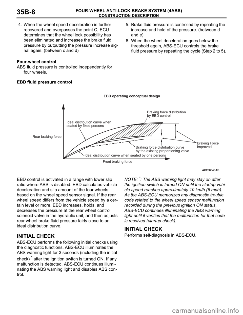
EBD control is activated in a range with lower slip
ratio where ABS is disabled. EBD calculates vehicle
deceleration and slip amount of the four wheels
based on the wheel speed sensor signal. If the rear
wheel speed differs from the vehicle speed by a cer
-
tain level or more, EBD increases, holds, and
decreases the pressure at the rear wheel control
solenoid valve in the hydraulic unit, and then adjusts
rear wheel brake fluid pressure fairly close to an
ideal distribution curve.
INITIAL CHECK
ABS-ECU performs the following initial checks using
the diagnostic functions. ABS-ECU illuminates the
ABS warning light for 3 seconds (including the initial
check)
* after the ignition switch is turned ON. If any
malfunction is detected, ABS-ECU continues illumi
-
nating the ABS warning light and disables ABS con-
trol.
NOTE: *: The ABS warning light may stay on after
the ignition switch is turned ON until the startup vehi
-
cle speed reaches approximately 10 km/h (6 mph).
As the ABS-ECU memorizes any diagnostic trouble
code related to the wheel speed sensor malfunction
recorded during the previous ignition ON status,
ABS-ECU continues illuminating the ABS warning
light until it verifies that the malfunction for that code
is resolved (startup check).
.
INITIAL CHECK
Performs self-diagnosis in ABS-ECU.
AC208548AB
Ideal distribution curve when
seated by fixed personsEBD operating conceptual design
Rear braking force
Ideal distribution curve when seated by one personsBraking force distribution curve
by the existing proportioning valveBraking force distribution
by EBD control
Front braking forceBraking Force
Improved
Page 220 of 241

CONSTRUCTION DESCRIPTION
FOUR-WHEEL ANTI-LOCK BRAKE SYSTEM (4ABS)35B-11
NOTE: .
•*1 This diagnostic trouble code is not set within
the vehicle speed of 20 km/h (12 mph) or less.
•*2 Turns ON when two or more wheels are faulty.
•*3 Stays ON until the vehicle speed reaches 10
km/h (6 mph) when the ignition switch is turned to
ON next time.
DIAGNOSTIC FUNCTION
ABS-ECU has the following functions for easier sys-
tem checks. The following items can be diagnosed
using scan tool.
•Diagnostic trouble code set
•Service data output
•Actuator test.
DIAGNOSTIC TROUBLE CODE SET
There are 43 diagnosis items. Since all the diagnos-
tic results are recorded in volatile memory
(EEPROM*), they are stored in the memory even
though the battery terminals are disconnected.
NOTE: .
•*EEPROM (Electrical Erasable & Programmable
ROM): Special type of memory that can be pro
-
grammed or erased electrically
•For each diagnosis item, refer to Service Manual.
.
SERVICE DATA OUTPUT
Using scan tool, the input data sent from the sensors
and switches can be read.
NOTE: For service data items, refer to Service Man-
ual.
.
C2116Abnormality in pump motor
power supply voltageExecutedProhibitedExtinguishedIlluminated*3
C1000Abnormality in stop light switch
circuitExecutedExecutedExtinguishedExtinguished
C2200Abnormality in ABS-ECUProhibitedProhibitedIlluminatesIlluminates
C2100Battery
voltage
problem (low
voltage)9.7 ± 0.3 V or
less
*1
ExecutedProhibitedExtinguishedIlluminates
8.0 ± 0.5 V or
less
*1
ProhibitedProhibitedIlluminatesIlluminates
C2101Battery
voltage
problem (high
voltage)18.0 ± 1.0 V or
moreProhibitedProhibitedIlluminatesIlluminates
C1395Brake fluid filling not completedExecutedExecutedExtinguishedFlashes (1 Hz)
C2203VIN not writtenExecutedExecutedExtinguishedIlluminates
C1608Implausible diagnosis dataExecutedExecutedExtinguishedExtinguished
U0001Bus offExecutedExecutedExtinguishedExtinguished
U0100Engine time-out errorExecutedExecutedExtinguishedExtinguished
U0141ETACS time-out errorExecutedExecutedExtinguishedExtinguished
U1415Variant coding not implementedExecutedProhibitedExtinguishedIlluminates
U1417Invalid variant coding value
(including wrong assembly)ExecutedProhibitedExtinguishedIlluminates
DTC
No.Item Countermeasures for failure
EBD control ABS control Brake
warning lightABS warning
light