height MITSUBISHI LANCER EVOLUTION X 2008 Workshop Manual
[x] Cancel search | Manufacturer: MITSUBISHI, Model Year: 2008, Model line: LANCER EVOLUTION X, Model: MITSUBISHI LANCER EVOLUTION X 2008Pages: 241, PDF Size: 8.26 MB
Page 50 of 241
BASE ENGINE
ENGINE MECHANICAL11A-6
PISTONS
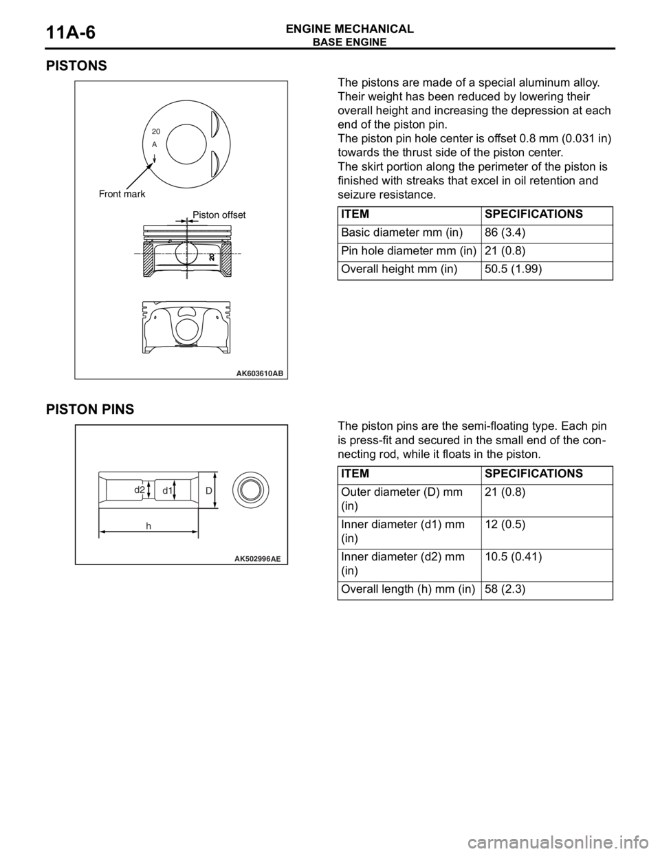
The pistons are made of a special aluminum alloy.
Their weight has been reduced by lowering their
overall height and increasing the depression at each
end of the piston pin.
The piston pin hole center is offset 0.8 mm (0.031 in)
towards the thrust side of the piston center.
The skirt portion along the perimeter of the piston is
finished with streaks that excel in oil retention and
seizure resistance.
PISTON PINS
The piston pins are the semi-floating type. Each pin
is press-fit and secured in the small end of the con
-
necting rod, while it floats in the piston.
20
A
AK603610
Front mark
Piston offset
AB
ITEMSPECIFICATIONS
Basic diameter mm (in)86 (3.4)
Pin hole diameter mm (in)21 (0.8)
Overall height mm (in)50.5 (1.99)
AK502996AE
D
hd1d2
ITEMSPECIFICATIONS
Outer diameter (D) mm
(in)21 (0.8)
Inner diameter (d1) mm
(in)12 (0.5)
Inner diameter (d2) mm
(in)10.5 (0.41)
Overall length (h) mm (in)58 (2.3)
Page 57 of 241
BASE ENGINE
ENGINE MECHANICAL11A-13
VA LV E S
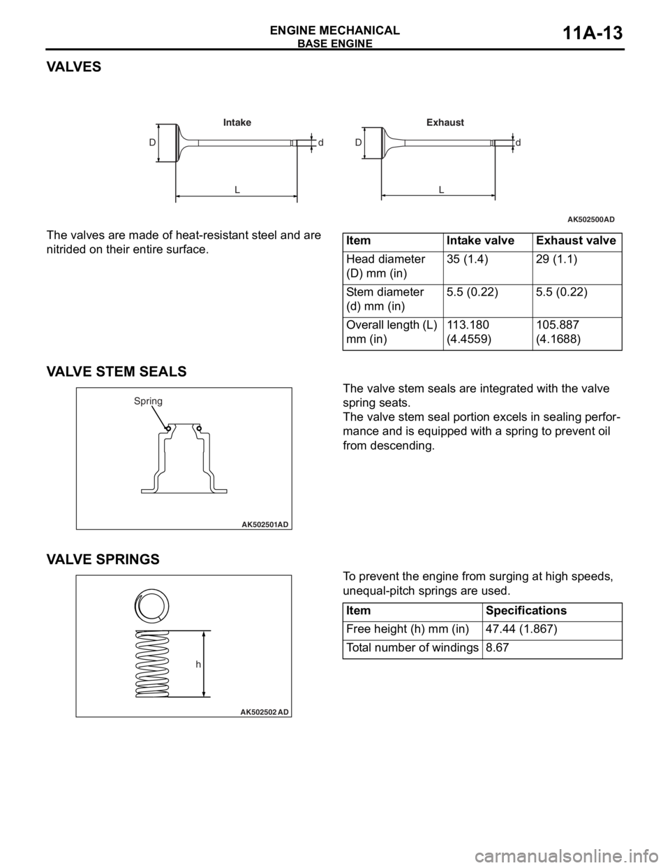
The valves are made of heat-resistant steel and are
nitrided on their entire surface.
VALVE STEM SEALS
The valve stem seals are integrated with the valve
spring seats.
The valve stem seal portion excels in sealing perfor-
mance and is equipped with a spring to prevent oil
from descending.
VA LV E S P R I N G S
To prevent the engine from surging at high speeds,
unequal-pitch springs are used.
AK502500
LL Dd dD
AD
Intake Exhaust
ItemIntake valveExhaust valve
Head diameter
(D) mm (in)35 (1.4)29 (1.1)
Stem diameter
(d) mm (in)5.5 (0.22)5.5 (0.22)
Overall length (L)
mm (in)113.180
(4.4559)105.887
(4.1688)
AK502501
Spring
AD
AK502502
h
AD
ItemSpecifications
Free height (h) mm (in)47.44 (1.867)
Total number of windings8.67
Page 151 of 241

GENERAL INFORMATION
INTERIOR52A-2
GENERAL INFORMATIONM2520000101013
Functionality, interior comfort, and safety have been
emphasized, giving interior design for elegance and
relaxation space. Various measures have been taken
to protect the environment and recycle resources.
FEATURES
Quality improvement
1. Two-tone interior
2. Full interior trim
Usability improvement
1. Armrest (floor console, rear seat, front door trim, rear door trim)
2. Cup holder (floor console, rear seat armrest)
3. Bottle holder (front door trim)
Convenient storage
1. Glove box
2. Seatback pocket (driver’s seat)
3. Card holder (glove box)
4. Tissue paper holder (floor console)
5. Floor console box
6. Door pocket (front door trim, rear door trim)
Safety improvement
1. Front and rear collision protection seat mecha-
nism (front seat)
2. ISO-FIX lower anchor (rear seat outside)
3. Upper tether anchor (rear shelf)
4. ELR 3-point seat belt (driver’s seat)
5. ELR/ALR 3-point seat belt (front passenger, rear)
6. Seat belt retractor with a driver's side preten-
sioner and force limiter
7. Seat belt retractor with a passenger’s side pre-
tensioner and force limiter
8. Headliner energy absorption rib
Consideration for the optimum driving position
1. Seat height adjustment (driver’s seat)
2. Head restraint with height adjustment (front, rear)
3. Seat slide adjustment (front)
Measures for resource recycling
1. Aggressively use PP materials that are easy to recycle and easy to stamp material symbols on
the plastic (resin) parts.
2. Reduction of chemical material (formaldehyde*,
organic solvent)
NOTE: *: Clear and colourless, toxic, irritating odour
Page 154 of 241
SEAT
INTERIOR52A-5
SEAT
FRONT SEATM2520004000996
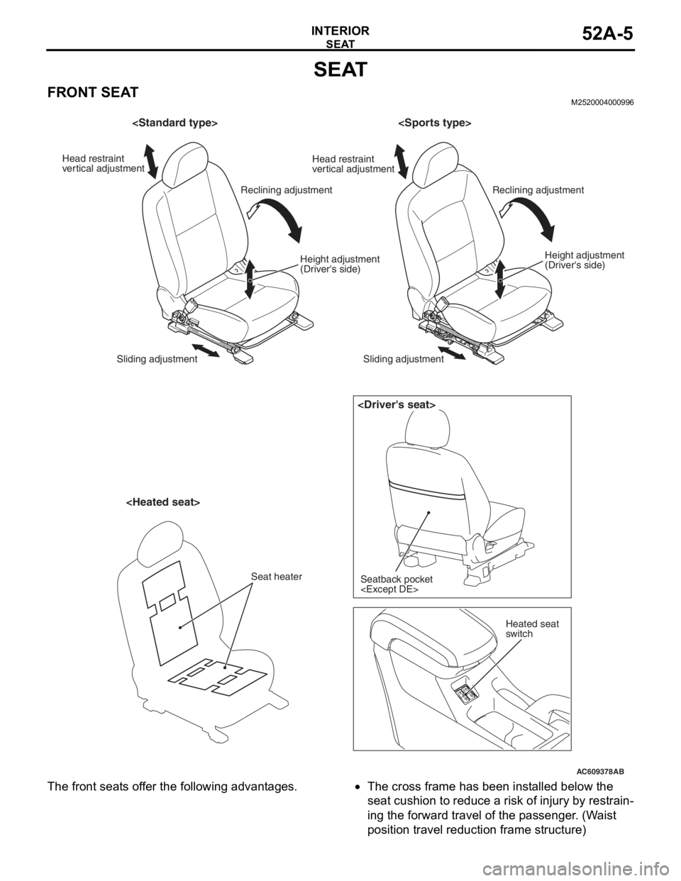
The front seats offer the following advantages.•The cross frame has been installed below the
seat cushion to reduce a risk of injury by restrain
-
ing the forward travel of the passenger. (Waist
position travel reduction frame structure)
AC609378
AB
Head restraint
vertical adjustment Head restraint
vertical adjustment
Reclining adjustment Reclining adjustment
Seatback pocket
switch
Height adjustment
(Driver's side)
Sliding adjustment Sliding adjustment
Seat heater
Height adjustment
(Driver's side)
Page 155 of 241

SEAT
INTERIOR52A-6
•The seat frame and head restraint have been
installed to the proper positions to minimize the
severity of whiplash injury at rear-end collision at
a low speed. (Whiplash injury reduction seat
structure)
•The overall height mechanism raises and lowers
the seat cushion together with the seatback, thus
the driver's posture is always kept at the best
position, resulting in the improved riding comfort.
•The pump-type height lever has been adopted for
easier operation with a light force by the vertical
adjustment system. Also, the height adjustment
amount has been increased for more optimum
driving position.
•The variable hardness pad has been adopted for
the sporty-look seat with increased bucket
amount of side bolster in order to establish the
sporty shape with support function
the standard shape which is basic and for actual
use and comfortable driving.
•Heated seats are available for the driver's and
passenger's seats.
•The genuine leather for the seat has been
upgraded to enhance the texture and luxury feel
-
ing.
SPECIFICATIONS FOR HEATED SEAT
ItemSpecifications
ENERGY CONSUMPTION WHIGH61 ± 6.1
LOW16 ± 1.6
THERMOSTAT °CON → OFF40 ± 4
OFF → ON30 ± 5
Page 182 of 241
FRONT SEAT ASSEMBLY
TSB Revision
INTERIOR52A-21
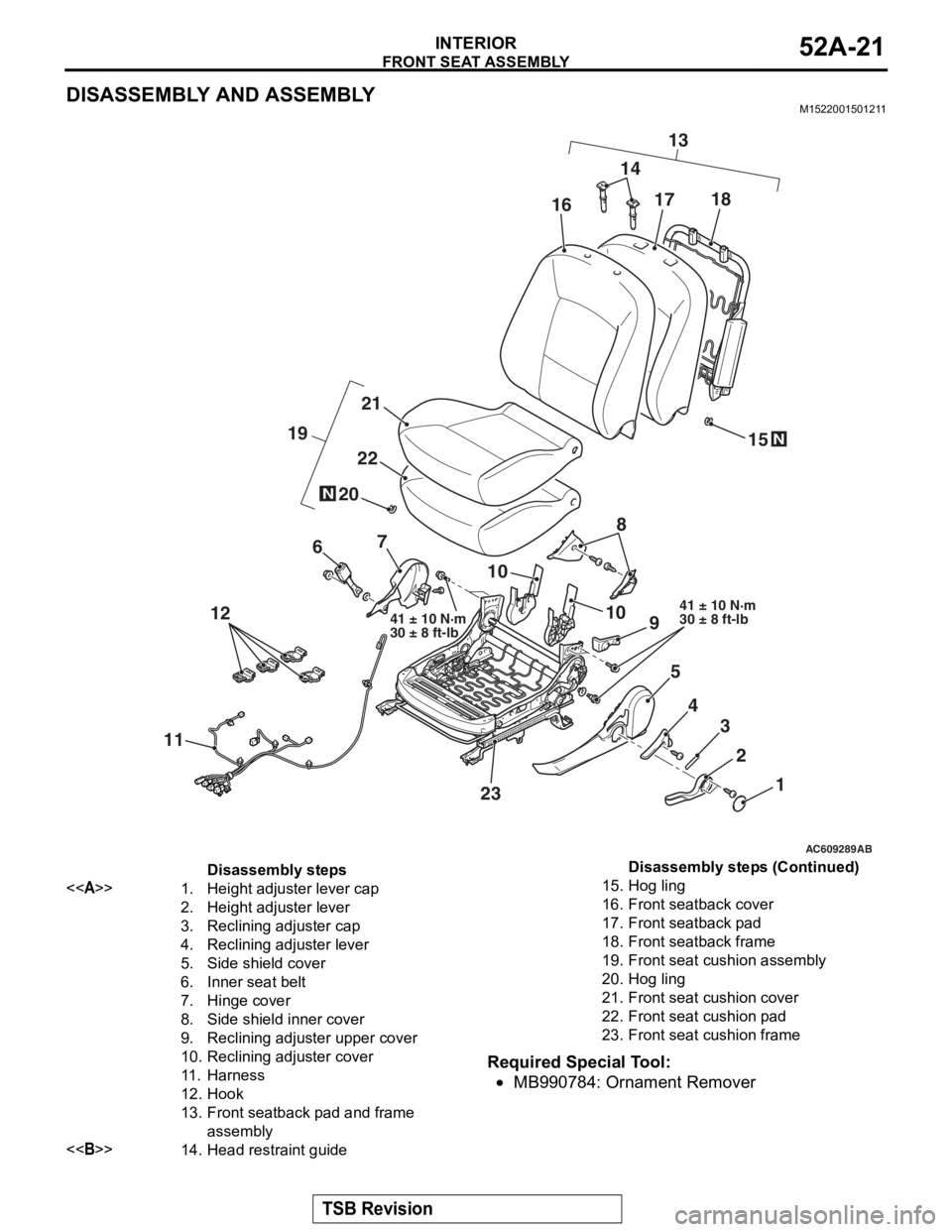
DISASSEMBLY AND ASSEMBLYM1522001501211
Required Special Tool:
•MB990784: Ornament Remover
AC506551
AC609289AB
1
2
3
4
5
9
10
67
12
11
23 14
13
N
10
20
19N
22
21
15
8
161718
41 ± 10 N·m
30 ± 8 ft-lb41 ± 10 N·m
30 ± 8 ft-lb
Disassembly steps
<>1.Height adjuster lever cap
2.Height adjuster lever
3.Reclining adjuster cap
4.Reclining adjuster lever
5.Side shield cover
6.Inner seat belt
7.Hinge cover
8.Side shield inner cover
9.Reclining adjust er upper cover
10.Reclining adjuster cover
11 .Harness
12.Hook
13.Front seatback pad and frame
assembly
<>14.Head restraint guide
15.Hog ling
16.Front seatback cover
17.Front seatback pad
18.Front seatback frame
19.Front seat cushion assembly
20.Hog ling
21.Front seat cushion cover
22.Front seat cushion pad
23.Front seat cushion frame
Disassembly steps (Continued)
Page 183 of 241
FRONT SEAT ASSEMBLY
TSB Revision
INTERIOR52A-22
REMOVAL SERVICE POINT
.
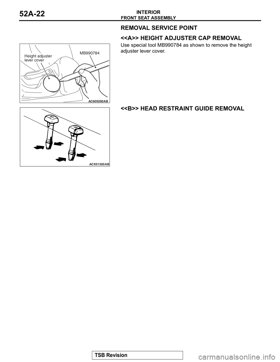
<> HEIGHT ADJUSTER CAP REMOVAL
Use special tool MB990784 as shown to remove the height
adjuster lever cover.
.
<> HEAD RESTRAINT GUIDE REMOVAL
AC609290
MB990784
AB
Height adjuster
lever cover
ACX01300AB
Page 223 of 241
GENERAL INFORMATION
REAR SUSPENSION34-2
GENERAL INFORMATIONM2340000100977
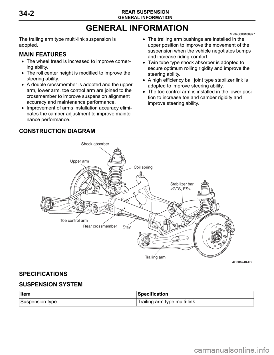
The trailing arm type multi-link suspension is
adopted.
.
MAIN FEATURES
•The wheel tread is increased to improve corner-
ing ability.
•The roll center height is modified to improve the
steering ability.
•A double crossmember is adopted and the upper
arm, lower arm, toe control arm are joined to the
crossmember to improve suspension alignment
accuracy and maintenance performance.
•Improvement of arms installation accuracy elimi-
nates the camber adjustment to improve mainte-
nance performance.
•The trailing arm bushings are installed in the
upper position to improve the movement of the
suspension when the vehicle negotiates bumps
and increase riding comfort.
•Twin tube type shock absorber is adopted to
secure optimum rolling rigidity and improve the
steering ability.
•A high efficiency ball joint type stabilizer link is
adopted to improve steering ability.
•The toe control arm is installed in the lower posi-
tion to increase toe and camber rigidity and
improve steering ability.
CONSTRUCTION DIAGRAM
SPECIFICATIONS
.
SUSPENSION SYSTEM
.
AC606248AB
Stabilizer bar
Trailing arm Stay Rear crossmember Toe control armCoil spring Shock absorber
Upper arm
ItemSpecification
Suspension typeTrailing arm type multi-link
Page 227 of 241
GENERAL INFORMATION
FRONT SUSPENSION33-2
GENERAL INFORMATIONM2330000100965
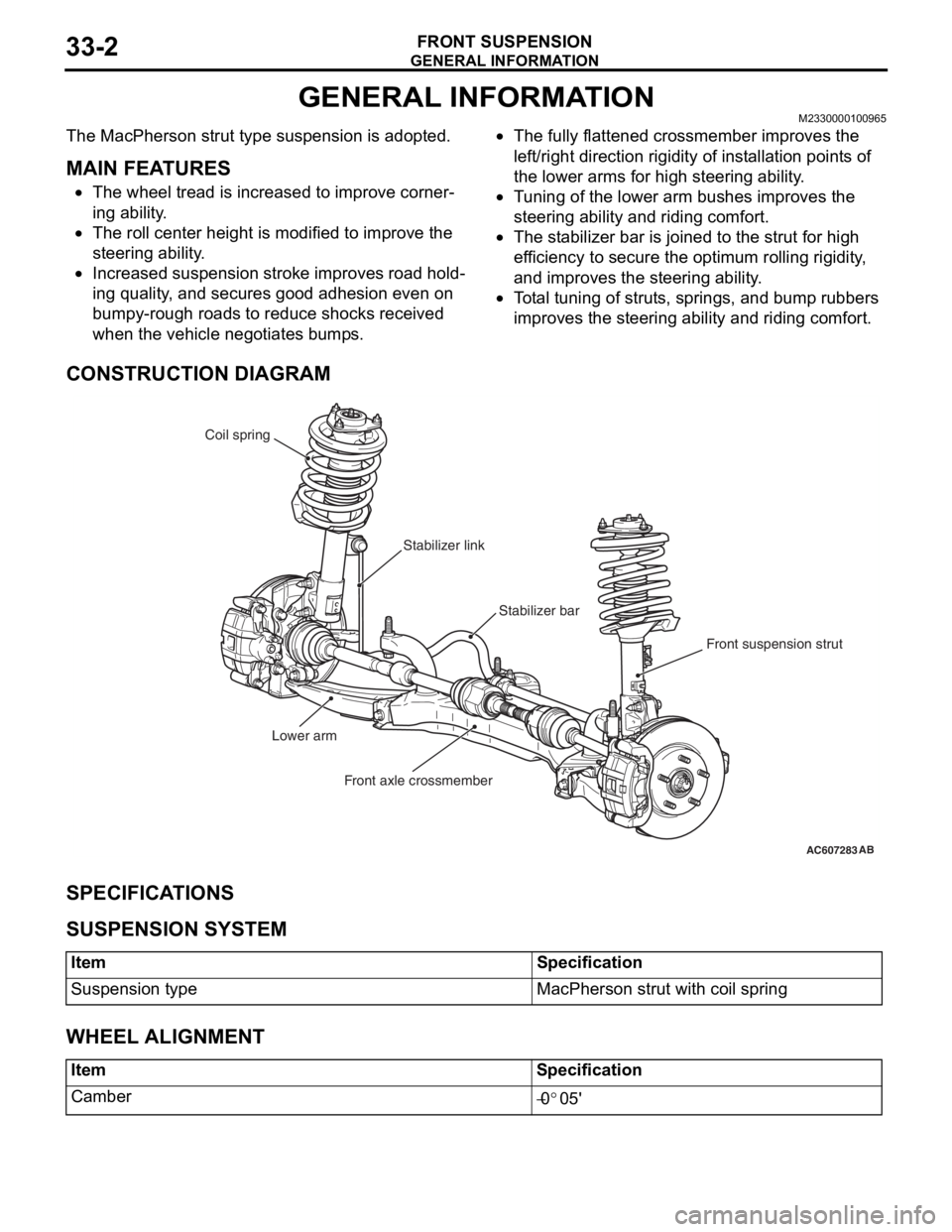
The MacPherson strut type suspension is adopted..
MAIN FEATURES
•The wheel tread is increased to improve corner-
ing ability.
•The roll center height is modified to improve the
steering ability.
•Increased suspension stroke improves road hold-
ing quality, and secures good adhesion even on
bumpy-rough roads to reduce shocks received
when the vehicle negotiates bumps.
•The fully flattened crossmember improves the
left/right direction rigidity of installation points of
the lower arms for high steering ability.
•Tuning of the lower arm bushes improves the
steering ability and riding comfort.
•The stabilizer bar is joined to the strut for high
efficiency to secure the optimum rolling rigidity,
and improves the steering ability.
•Total tuning of struts, springs, and bump rubbers
improves the steering ability and riding comfort.
CONSTRUCTION DIAGRAM
SPECIFICATIONS
.
SUSPENSION SYSTEM
.
WHEEL ALIGNMENT
AC607283AB
Stabilizer bar Coil spring
Front suspension strut Stabilizer link
Lower arm
Front axle crossmember
ItemSpecification
Suspension typeMacPherson strut with coil spring
ItemSpecification
Camber−0°05'