oil level MITSUBISHI LANCER EVOLUTION X 2008 Workshop Manual
[x] Cancel search | Manufacturer: MITSUBISHI, Model Year: 2008, Model line: LANCER EVOLUTION X, Model: MITSUBISHI LANCER EVOLUTION X 2008Pages: 241, PDF Size: 8.26 MB
Page 97 of 241
GENERAL DESCRIPTION
MULTIPORT FUEL SYSTEM (MFI)13A-3
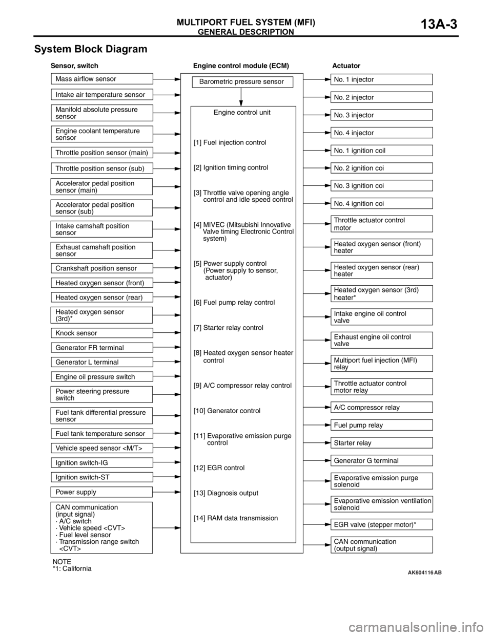
System Block Diagram
AK604116
Mass airflow sensor
Intake air temperature sensor
Intake camshaft position
sensor
Exhaust camshaft position
sensor
Crankshaft position sensor Throttle position sensor (main)
Throttle position sensor (sub)
Accelerator pedal position
sensor (sub) Accelerator pedal position
sensor (main) Engine coolant temperature
sensor Manifold absolute pressure
sensor
Heated oxygen sensor (front)
Heated oxygen sensor (rear)
Power steering pressure
switch Engine oil pressure switch Generator L terminal
Ignition switch-ST
Power supply Ignition switch-IG
CAN communication
(input signal)
· A/C switch
· Vehicle speed
· Fuel level sensor
· Transmission range switch
sensor Heated oxygen sensor
(3rd)*
Knock sensor
Generator FR terminal
Fuel tank temperature sensor
Vehicle speed sensor
[1] Fuel injection control
[2] Ignition timing control
[3] Throttle valve opening angle
control and idle speed control
[4]
MIVEC (Mitsubishi Innovative
Valve timing Electronic Control
system)
[5] Power supply control
(Power supply to sensor,
actuator)
[6] Fuel pump relay control
[7] Starter relay control
[8] Heated oxygen sensor heater
control
[9] A/C compressor relay control
[10] Generator control
[11] Evaporative emission purge
control
[12] EGR control
[13] Diagnosis output
[14] RAM data transmission
CAN communication
(output signal) Intake engine oil control
valve
A/C compressor relay No. 2 injector
No. 3 injector
No. 4 injector
Heated oxygen sensor (front)
heater
Heated oxygen sensor (rear)
heater Throttle actuator control
motor
Throttle actuator control
motor relay No. 1 injector
No. 1 ignition coil
No. 2 ignition coi
No. 3 ignition coi
No. 4 ignition coi
Fuel pump relay
Generator G terminal Heated oxygen sensor (3rd)
heater*
Multiport fuel injection (MFI)
relay Exhaust engine oil control
valve
Evaporative emission ventilation
solenoid Evaporative emission purge
solenoid
EGR valve (stepper motor)*
Starter relay
AB
Sensor, switch Engine control module (ECM) Actuator
NOTE
*1: California
Page 98 of 241
GENERAL DESCRIPTION
MULTIPORT FUEL SYSTEM (MFI)13A-4
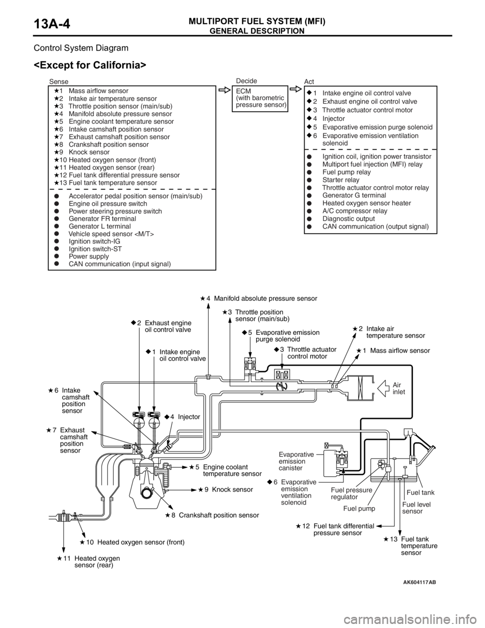
Control System Diagram
AK604117
Fuel level
sensorFuel tank Air
inlet
2 Exhaust engine
oil control valve
1 Intake engine
oil control valve4 Manifold absolute pressure sensor
2 Intake air
temperature sensor
1 Mass airflow sensor
6 Intake
camshaft
position
sensor
7 Exhaust
camshaft
position
sensor
3 Throttle position
sensor (main/sub)
5 Evaporative emission
purge solenoid
3 Throttle actuator
control motor
12 Fuel tank differential
pressure sensor
13 Fuel tank
temperature
sensor10 Heated oxygen sensor (front)
11 Heated oxygen
sensor (rear)
8 Crankshaft position sensor5 Engine coolant
temperature sensor
9 Knock sensor
4 Injector
Fuel pump Fuel pressure
regulator Evaporative
emission
canister
6 Evaporative
emission
ventilation
solenoid
1 Mass airflow sensor
2 Intake air temperature sensor
3 Throttle position sensor (main/sub)
4 Manifold absolute pressure sensor
5 Engine coolant temperature sensor
6 Intake camshaft position sensor
7 Exhaust camshaft position sensor
8 Crankshaft position sensor
9 Knock sensor
10 Heated oxygen sensor (front)
11 Heated oxygen sensor (rear)
12 Fuel tank differential pressure sensor
13 Fuel tank temperature sensor
Ignition switch-IG
Ignition switch-ST
Power supply
CAN communication (input signal)1 Intake engine oil control valve
2 Exhaust engine oil control valve
3 Throttle actuator control motor
4 Injector
5 Evaporative emission purge solenoid
6 Evaporative emission ventilation
solenoid
Ignition coil, ignition power transistor
Multiport fuel injection (MFI) relay
Fuel pump relay
Starter relay
Throttle actuator control motor relay
Generator G terminal
Heated oxygen sensor heater
A/C compressor relay
Diagnostic output
CAN communication (output signal) SenseAct
Engine oil pressure switch
Power steering pressure switch
Generator FR terminal
Generator L terminal
Vehicle speed sensor
Decide
ECM
(with barometric
pressure sensor)
AB
Page 99 of 241
GENERAL DESCRIPTION
MULTIPORT FUEL SYSTEM (MFI)13A-5
AK604118
Fuel tank
Fuel level
sensor Air
inlet
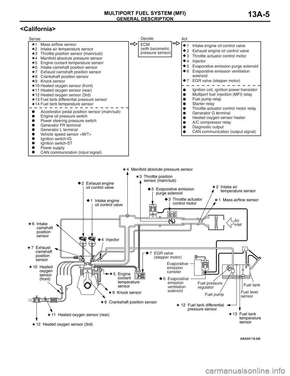
2 Exhaust engine
oil control valve
1 Intake engine
oil control valve4 Manifold absolute pressure sensor
2 Intake air
temperature sensor
1 Mass airflow sensor
6 Intake
camshaft
position
sensor
7 Exhaust
camshaft
position
sensor
3 Throttle position
sensor (main/sub)
5 Evaporative emission
purge solenoid
3 Throttle actuator
control motor
12 Fuel tank differential
pressure sensor
13 Fuel tank
temperature
sensor11 Heated oxygen sensor (rear)
10 Heated
oxygen
sensor
(front)
12 Heated oxygen sensor (3rd)
8 Crankshaft position sensor5 Engine
coolant
temperature
sensor
9 Knock sensor
4 Injector
Fuel pump Fuel pressure
regulator Evaporative
emission
canister
6 Evaporative
emission
ventilation
solenoid
7 EGR valve
(stepper motor)
1 Mass airflow sensor
2 Intake air temperature sensor
3 Throttle position sensor (main/sub)
4 Manifold absolute pressure sensor
5 Engine coolant temperature sensor
6 Intake camshaft position sensor
7 Exhaust camshaft position sensor
8 Crankshaft position sensor
9 Knock sensor
10 Heated oxygen sensor (front)
11 Heated oxygen sensor (rear)
12 Heated oxygen sensor (3rd)
13 Fuel tank differential pressure sensor
14 Fuel tank temperature sensor
Ignition switch-IG
Ignition switch-ST
Power supply
CAN communication (input signal)1 Intake engine oil control valve
2 Exhaust engine oil control valve
3 Throttle actuator control motor
4 Injector
5 Evaporative emission purge solenoid
6 Evaporative emission ventilation
solenoid
7 EGR valve (stepper motor)
Ignition coil, ignition power transistor
Multiport fuel injection (MFI) relay
Fuel pump relay
Starter relay
Throttle actuator control motor relay
Generator G terminal
Heated oxygen sensor heater
A/C compressor relay
Diagnostic output
CAN communication (output signal) SenseAct
Engine oil pressure switch
Power steering pressure switch
Generator FR terminal
Generator L terminal
Vehicle speed sensor
Decide
ECM
(with barometric
pressure sensor)
AB
Page 117 of 241
ACTUATOR
MULTIPORT FUEL SYSTEM (MFI)13A-24
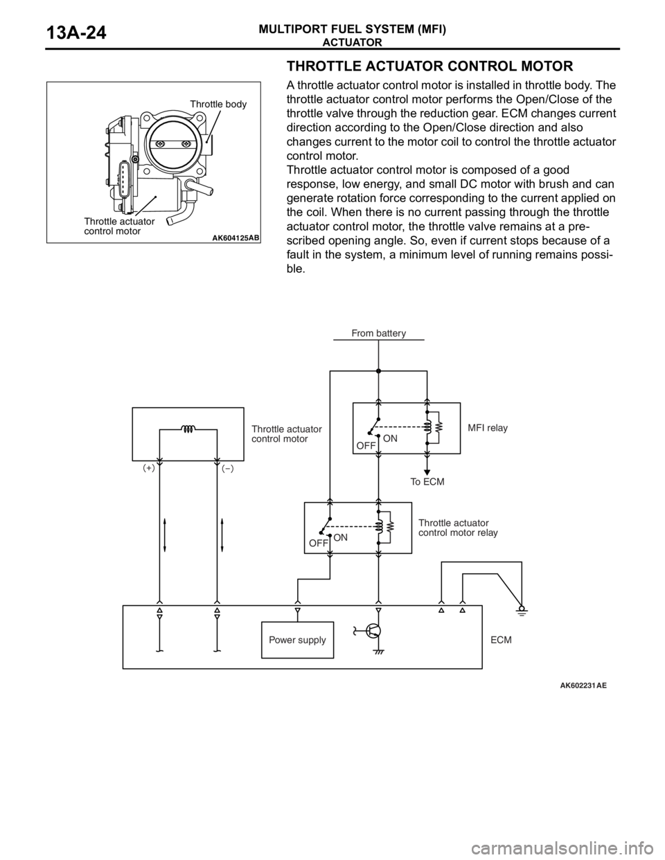
THROTTLE ACTUATOR CONTROL MOTOR
A throttle actuator control motor is installed in throttle body. The
throttle actuator control motor performs the Open/Close of the
throttle valve through the reduction gear. ECM changes current
direction according to the Open/Close direction and also
changes current to the motor coil to control the throttle actuator
control motor.
Throttle actuator control motor is composed of a good
response, low energy, and small DC motor with brush and can
generate rotation force corresponding to the current applied on
the coil. When there is no current passing through the throttle
actuator control motor, the throttle valve remains at a pre
-
scribed opening angle. So, even if current stops because of a
fault in the system, a minimum level of running remains possi
-
ble.
AK604125AB
Throttle body
Throttle actuator
control motor
AK602231
Throttle actuator
control motor
Throttle actuator
control motor relayMFI relay
To ECM
Power supplyOFFON
OFF
ON
AE
From battery
ECM
Page 215 of 241
CONSTRUCTION DESCRIPTION
FOUR-WHEEL ANTI-LOCK BRAKE SYSTEM (4ABS)35B-6
CONSTRUCTION DESCRIPTION
SENSORM2351001000494
Wheel speed sensor
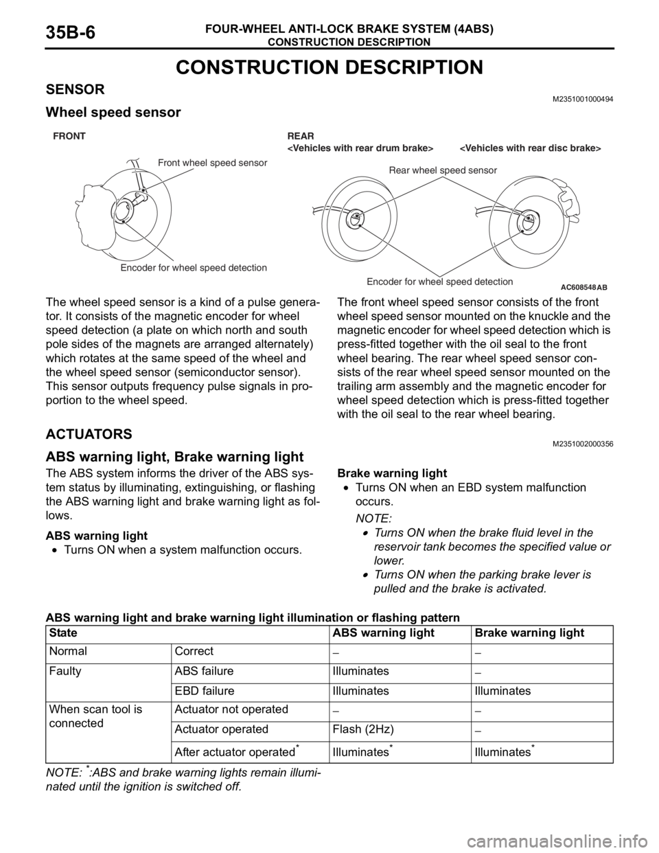
The wheel speed sensor is a kind of a pulse genera-
tor. It consists of the magnetic encoder for wheel
speed detection (a plate on which north and south
pole sides of the magnets are arranged alternately)
which rotates at the same speed of the wheel and
the wheel speed sensor (semiconductor sensor).
This sensor outputs frequency pulse signals in pro
-
portion to the wheel speed.
The front wheel speed sensor consists of the front
wheel speed sensor mounted on the knuckle and the
magnetic encoder for wheel speed detection which is
press-fitted together with the oil seal to the front
wheel bearing. The rear wheel speed sensor con
-
sists of the rear wheel speed sensor mounted on the
trailing arm assembly and the magnetic encoder for
wheel speed detection which is press-fitted together
with the oil seal to the rear wheel bearing.
ACTUATORSM2351002000356
ABS warning light, Brake warning light
The ABS system informs the driver of the ABS sys-
tem status by illuminating, extinguishing, or flashing
the ABS warning light and brake warning light as fol
-
lows.
ABS warning light
•Turns ON when a system malfunction occurs.
Brake warning light
•Turns ON when an EBD system malfunction
occurs.
NOTE: .
•Turns ON when the brake fluid level in the
reservoir tank becomes the specified value or
lower.
•Turns ON when the parking brake lever is
pulled and the brake is activated.
ABS warning light and brake warning light illumination or flashing pattern
NOTE: *:ABS and brake warning lights remain illumi-
nated until the ignition is switched off.
AC608548
AB
FRONT REAR
Front wheel speed sensor
Rear wheel speed sensor
Encoder for wheel speed detection
Encoder for wheel speed detection
StateABS warning lightBrake warning light
NormalCorrect−−
FaultyABS failureIlluminates−
EBD failureIlluminatesIlluminates
When scan tool is
connectedActuator not operated−−
Actuator operatedFlash (2Hz)−
After actuator operated*Illuminates*Illuminates*
Page 241 of 241
OIL RESERVOIR
POWER STEERING37-8
OIL RESERVOIRM2370005000376
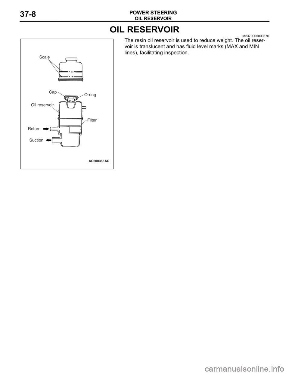
The resin oil reservoir is used to reduce weight. The oil reser-
voir is translucent and has fluid level marks (MAX and MIN
lines), facilitating inspection.
AC200365 AC
Scale
Cap
O-ring
Filter Oil reservoir
Return
Suction