window MITSUBISHI LANCER EVOLUTION X 2008 Workshop Manual
[x] Cancel search | Manufacturer: MITSUBISHI, Model Year: 2008, Model line: LANCER EVOLUTION X, Model: MITSUBISHI LANCER EVOLUTION X 2008Pages: 241, PDF Size: 8.26 MB
Page 38 of 241

HEATER CONTROL
HEATER, AIR CONDITIONING AND VENTILATION55-6
HEATER CONTROLM2551000900421
HEATER CONTROLLER
.
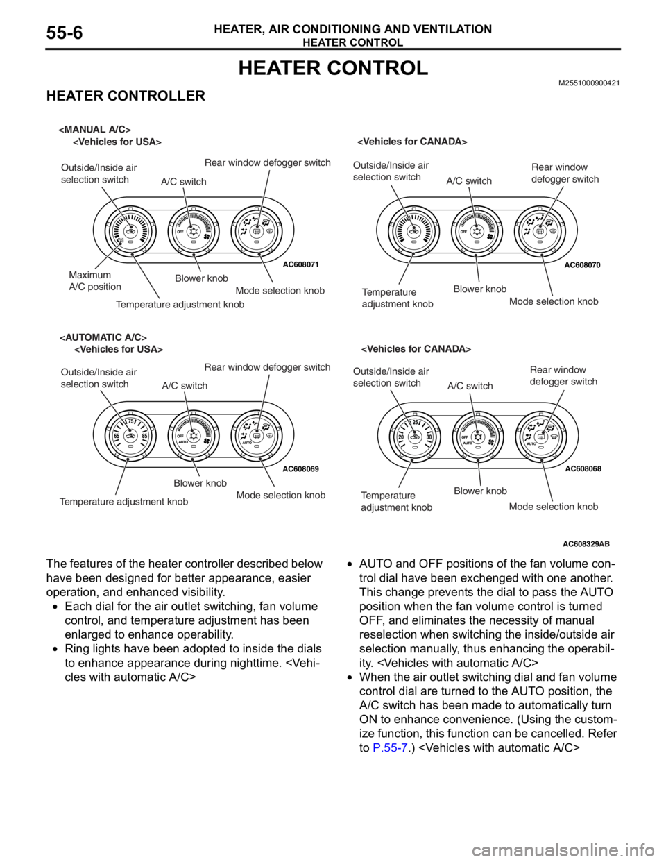
The features of the heater controller described below
have been designed for better appearance, easier
operation, and enhanced visibility.
•Each dial for the air outlet switching, fan volume
control, and temperature adjustment has been
enlarged to enhance operability.
•Ring lights have been adopted to inside the dials
to enhance appearance during nighttime.
cles with automatic A/C>
•AUTO and OFF positions of the fan volume con-
trol dial have been exchenged with one another.
This change prevents the dial to pass the AUTO
position when the fan volume control is turned
OFF, and eliminates the necessity of manual
reselection when switching the inside/outside air
selection manually, thus enhancing the operabil
-
ity.
•When the air outlet switching dial and fan volume
control dial are turned to the AUTO position, the
A/C switch has been made to automatically turn
ON to enhance convenience. (Using the custom
-
ize function, this function can be cancelled. Refer
to
P.55-7.)
AC608071AC608070
AC608069AC608068
AC608329
Outside/Inside air
selection switch
Maximum
A/C position
Temperature adjustment knob
A/C switch
Blower knob
Rear window defogger switch
Mode selection knob
selection switch
Temperature
adjustment knobBlower knob
A/C switch
Rear window
defogger switch
Mode selection knob
Outside/Inside air
selection switch
Temperature adjustment knob
A/C switch
Blower knob
Mode selection knob
Rear window defogger switch
selection switch
Temperature
adjustment knobBlower knob
A/C switch
Mode selection knob
Rear window
defogger switch
AB
Page 39 of 241

A/C-ECU
HEATER, AIR CONDITIONING AND VENTILATION55-7
A/C-ECUM2551001200265
CONTROL
.
FORCED DEF CONTROL
When air outlet position is switched to DEF, A/C is
automatically turned ON, and outside/inside air
selection damper is set to the fresh air position to
quickly defrost the windshield screen.
.
MAX A/C CONTROL
When the temperature adjustment knob is turned to
the maximum A/C position with the blower knob at
position other than OFF, the following controls are
made by the A/C-ECU.
NOTE: "*" Manual operation is disabled during max
A/C control.
.
MAX COOL, MAX HOT CONTROL
When the set temperature is at 18.0 °C <61°F>
(MAX COOL) or at 32.0
°C <89°F> (MAX HOT) with
the air outlet and air volume at the AUTO positions,
the following controls are made automatically by the
A/C-ECU.
NOTE: "*" indicates that when the automatic control
is not cancelled using the customise function, the
manual operation is disabled.
.
REAR WINDOW DEFOGGER TIMER
CONTROL
In order to prevent battery consumption, the defog-
ger is automatically turned OFF, 20 minutes after it is
turned ON.
.
IDLE-UP CONTROL
A/C-ECU and the engine ECU communicate with
each other through the CAN communication. The
idle-up speed of the engine is controlled in two steps
depending on the A/C load to secure the air cooling
performance during summer and to enhance fuel
economy in seasons with moderate temperature.
.
DETECTION CONTROL FOR
REFRIGERANT LEAKS
A/C-ECU determines if the refrigerant amount is less
than specified or refrigerant pressure is abnormal by
using the ambient temperature (ambient temperature
sensor to measure refrigerant inflation rate) and
refrigerant pressure (measured by the A/C pressure
sensor). When refrigerant amount or refrigerant pres
-
sure is judged abnormal, the compressor is cut-off to
protect the A/C system.
NOTE: When abnormality occurs, the A/C indicator
flashes.
.
PROTECTION CONTROL AT AIR BAG
DEPLOYMENT (DURING COLLISION)
When the air bag deployment is detected, the A/C
system is stopped.
.
CUSTOMISE FUNCTION
Depending on the user's preference, the following
functions can be selected. The programmed informa
-
tion is held even when the battery is disconnected.
•Automatic control for inside/outside air selection
Press and hold (approximately for 10 seconds)
the inside/outside air selection switch to cancel
the automatic control for inside/outside air selec
-
tion.
•A/C automatic control
Press and hold (approximately for 10 seconds)
the A/C switch to cancel the A/C automatic con
-
trol.
Subject to controlMAX COOL
Air mix damperMAX COOL position
Air outlet modeSelected position
Air volumeSelected position
Outside/inside air
selection damperAir recirculation position*
Air conditioner switchON*
Subject to
controlMAX COOLMAX HOT
Air mix
damperMAX COOL
positionMAX HOT
position
Air outlet
modeFACE positionFOOT position
Air volumeMaximumMaximum
Outside/insid
e air
selection
damperAir recirculation
position*Fresh air
position*
Air
conditioner
switchON*OFF*
Page 42 of 241

DUCT
HEATER, AIR CONDITIONING AND VENTILATION55-10
DUCTM2551001300358
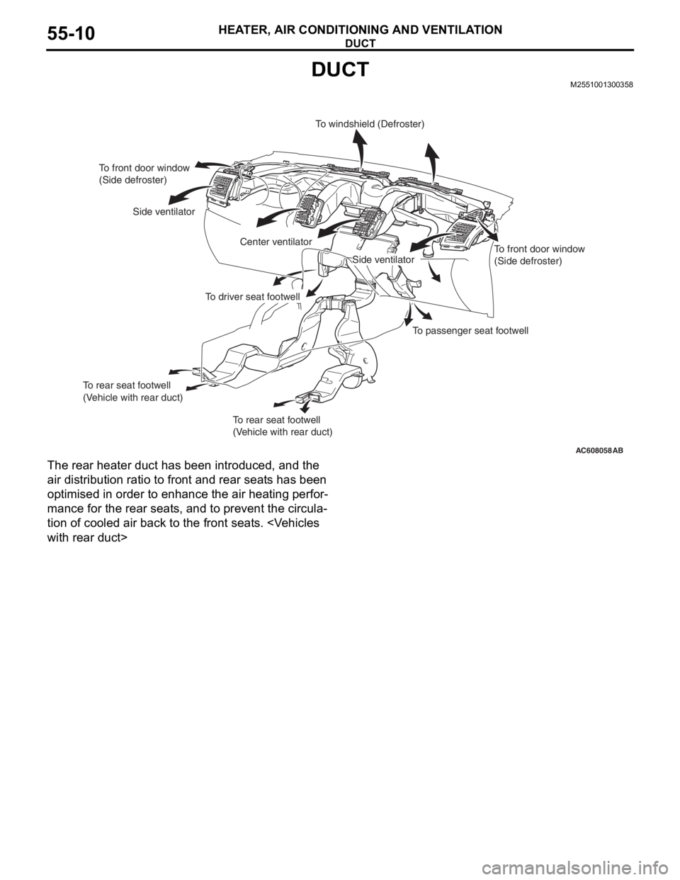
The rear heater duct has been introduced, and the
air distribution ratio to front and rear seats has been
optimised in order to enhance the air heating perfor
-
mance for the rear seats, and to prevent the circula-
tion of cooled air back to the front seats.
AC608058
To front door window
(Side defroster)
Side ventilator
Center ventilatorTo windshield (Defroster)
To front door window
(Side defroster)
To passenger seat footwell
To driver seat footwell
To rear seat footwell
(Vehicle with rear duct)
To rear seat footwell
(Vehicle with rear duct)
Side ventilator
AB
Page 174 of 241

DOOR TRIM
TSB Revision
INTERIOR52A-13
DOOR TRIM
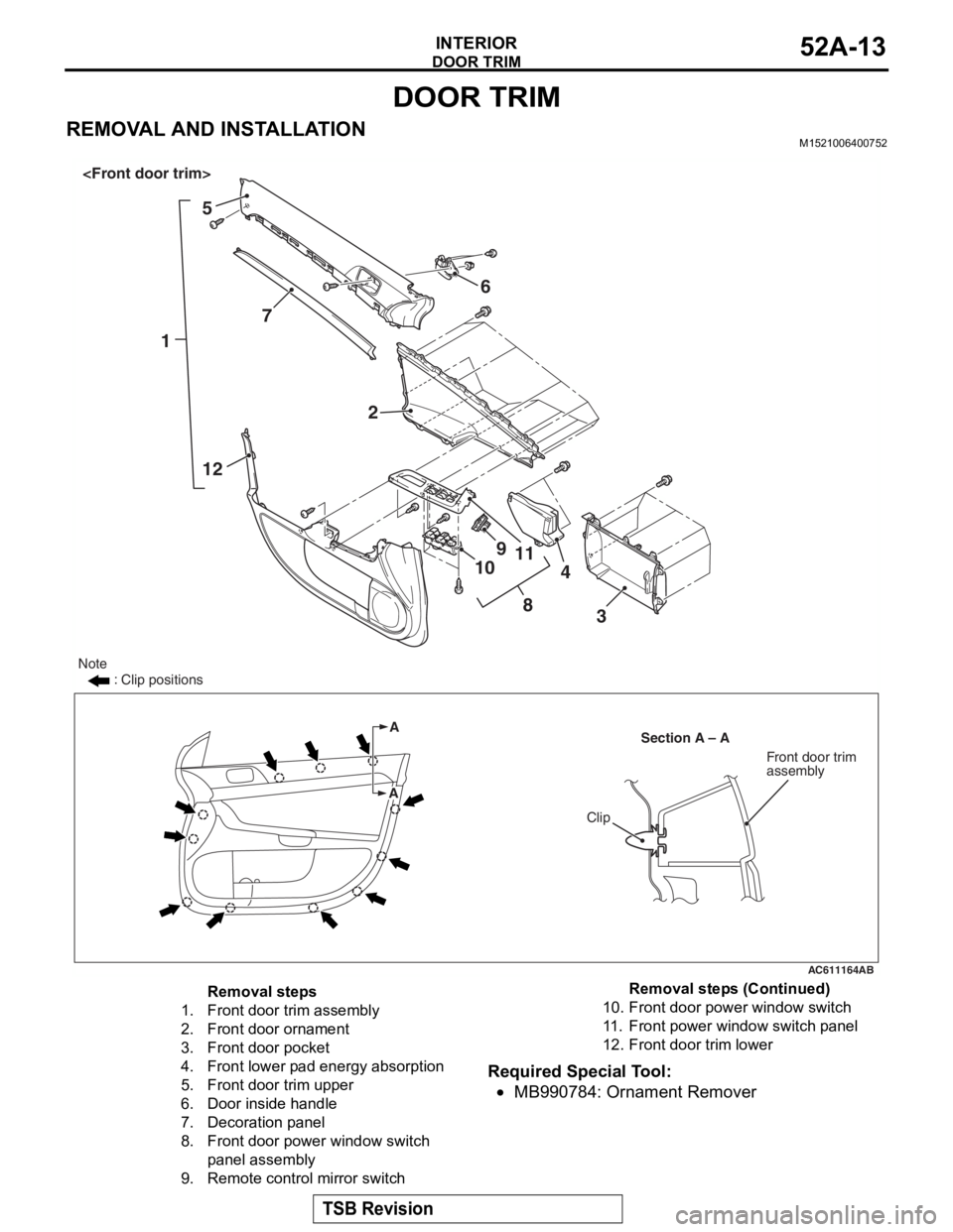
REMOVAL AND INSTALLATIONM1521006400752
Required Special Tool:
•MB990784: Ornament Remover
AC611164
15
7
12 6
2
8
9
10 11
3
4
A
Section A – A
Note
: Clip positions
A
Clip
Front door trim
assembly
AB
Removal steps
1.Front door trim assembly
2.Front door ornament
3.Front door pocket
4.Front lower pad energy absorption
5.Front door trim upper
6.Door inside handle
7.Decoration panel
8.Front door power window switch
panel assembly
9.Remote control mirror switch
10.Front door power window switch
11 .Front power window switch panel
12.Front door trim lower
Removal steps (Continued)
Page 175 of 241

DOOR TRIM
TSB Revision
INTERIOR52A-14
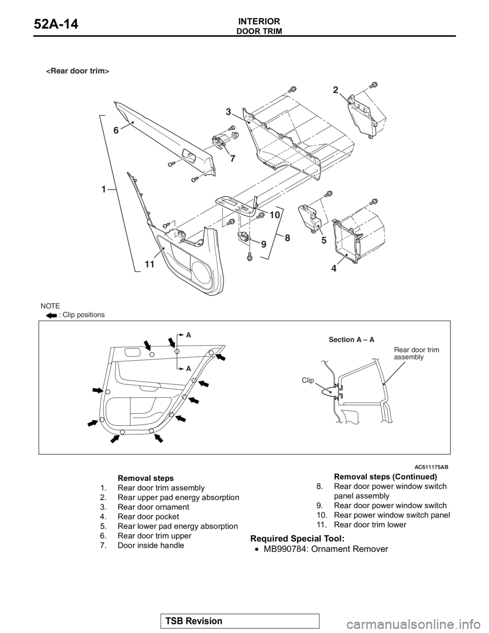
Required Special Tool:
•MB990784: Ornament Remover
AC611175
A
ASection A – A
Clip
Rear door trim
assembly
16
11 2
3
8
10
9 5
4
NOTE : Clip positions
AB
7
Removal steps
1.Rear door trim assembly
2.Rear upper pad energy absorption
3.Rear door ornament
4.Rear door pocket
5.Rear lower pad energy absorption
6.Rear door trim upper
7.Door inside handle
8.Rear door powe r window switch
panel assembly
9.Rear door powe r window switch
10.Rear power window switch panel
11 .Rear door trim lower
Removal steps (Continued)