lock MITSUBISHI LANCER IX 2006 User Guide
[x] Cancel search | Manufacturer: MITSUBISHI, Model Year: 2006, Model line: LANCER IX, Model: MITSUBISHI LANCER IX 2006Pages: 800, PDF Size: 45.03 MB
Page 105 of 800

IGNITION SYSTEM
ENGINE ELECTRICAL16-43
DETONATION SENSOR
REMOVAL AND INSTALLATION
M1163002801269
CAUTION
•When the detonation sensor replacement is performed, use the M.U.T.-II/III to initialise the learning
value (Refer to GROUP 00, Precautions Before Service
− Initialisation Procedure for Learning Value
in MPI Engine
P.00-19).
•
AC303971
2 1
23 ± 2 N·m
AB
<4G1>Cylinder block
(Intake side)
AC303972
2 1
23 ± 2 N·mAB
<4G6>Inlet manifold
Removal steps
1.Engine control detonation sensor
connector
<>>>A<<2.Engine control detonation sensor
Do not drop or hit the detonation sensor against other components. Internal damage may result,
and the detonation sensor will need to be replaced.
Page 108 of 800
ENGINE CONTROL
ENGINE AND EMISSION CONTROL17-2
ENGINE CONTROL
GENERAL INFORMATIONM1171000100277
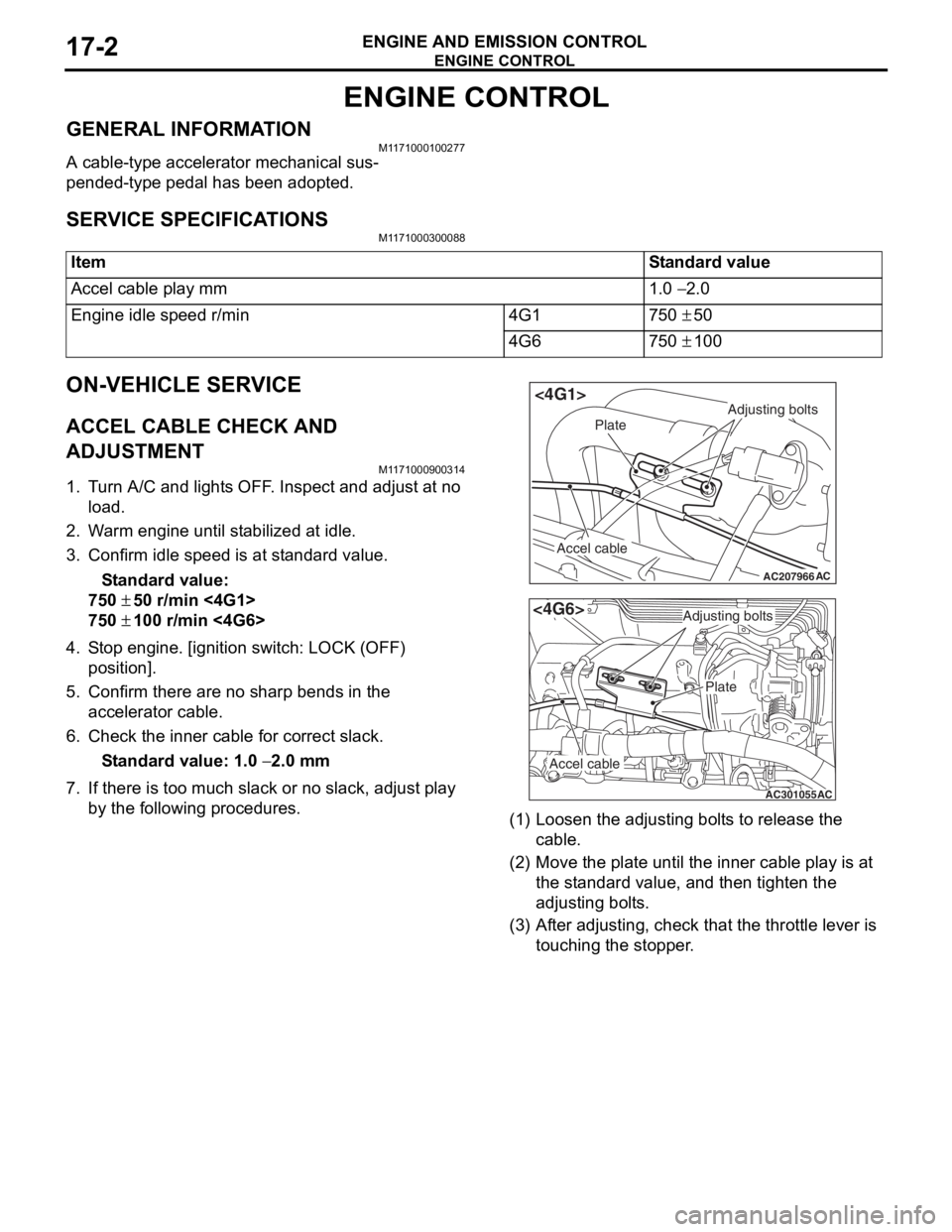
A cable-type accelerator mechanical sus-
pended-type pedal has been adopted.
SERVICE SPECIFICATIONS
M1171000300088
ItemStandard value
Accel cable play mm1.0 − 2.0
Engine idle speed r/min4G1750 ± 50
4G6750 ± 100
ON-VEHICLE SERVICE
ACCEL CABLE CHECK AND
ADJUSTMENT
M1171000900314
1. Turn A/C and lights OFF. Inspect and adjust at no load.
2. Warm engine until stabilized at idle.
3. Confirm idle speed is at standard value.
Standard value:
750 ± 50 r/min <4G1>
750 ± 100 r/min <4G6>
4. Stop engine. [ignition switch: LOCK (OFF)
position].
5. Confirm there are no sharp bends in the accelerator cable.
6. Check the inner cable for correct slack.
Standard value: 1.0 − 2.0 mm
7. If there is too much slack or no slack, adjust play by the following procedures.
AC207966
Adjusting bolts
Plate
Accel cable
AC
<4G1>
AC301055
Adjusting bolts
Plate
Accel cable
AC
<4G6>
(1) Loosen th e adjusting bo lt s to re lease the
cab l e.
(2) M o v e th e pla t e until the inne r cab l e play is a t
the st andard value, an d then tighte n the
adjusting bo lt s.
(3) A f t e r adju s ting, check that the thro ttle leve r is
touching the stoppe r .
Page 117 of 800
EMISSION CONTROL
ENGINE AND EMISSION CONTROL17-11
2. Plug the nipple from which the vacuum hose was removed.
3. When the engine is cold or hot, apply a vacuum of 53 kPa, and check the condition of the vacuum.
When engine is cold
(Engine coolant temperature: 40°C or less)
Engine conditionNormal condition
At idleVacuum is maintained.
3,000 r/min
When engine is hot
(Engine coolant temperature: 80°C or higher)
Engine conditionNormal condition
At idleVacuum is maintained.
3,000 r/min (within 3
minutes after engine
starts)Vacuum will leak.
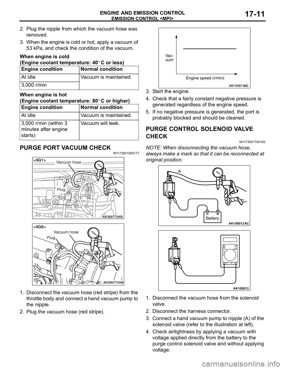
PURGE PORT VACUUM CHECKM1173001500177
AK300773
<4G1>
AB
Plug
Vacuum hose
AK300774
<4G6>
AB
Plug
Vacuum hose
1.Disco nnect th e vacuum ho se (red st ripe) from the
throttle body and connect a hand vacuum pump to
th e nip p le.
2.Plu g the vacuum hose (red stripe).
AK100011AC
Vac-
uum
Engine speed (r/min)
3.S t art the engine.
4.Check t hat a f a irly co nst ant n egative p r essure is
g enerate d regard l ess of the en gine spee d.
5.If no neg ative pressur e is genera t ed, th e port is
p r obably blocked an d sh ould be cleane d.
PURGE CONTROL SOLENOID VA L V E
CHECK
M1173 0017 0019 3
NOTE: Whe n discon nect i ng th e va cuum hose,
always make a mark so th at it can be reconnected at
original p o sition.
AK100012AC
Battery
A
AK100013
1.
Disco nnect the vacu um h o se f r om th e solenoid
valve.
2.Disco nnect the ha rness connector .
3.Con nect a ha nd vacu um pump to nipp le (A) of the
solen o id valve (ref e r to th e ill ust r ation at le f t ).
4.Check a i rtig htness b y app lying a vacuum with
volt age applied d i rectly from t he batt e ry to the
p u rge con t rol so leno id valve an d without app lying
volt age .
Page 122 of 800
EMISSION CONTROL
ENGINE AND EMISSION CONTROL17-16
5. Replace the gasket, and tighten to the specified torque.
Tightening torque:
<4G1> 21 ± 4 N⋅m
<4G6> 20 ± 2 N⋅m
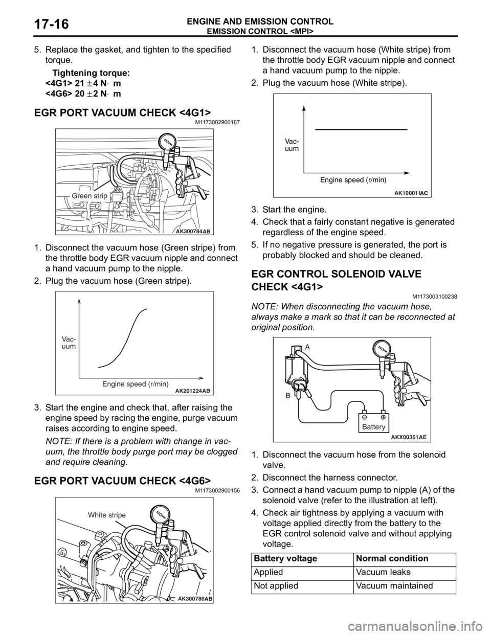
EGR PORT VACUUM CHECK <4G1>M1173002900167
AK300784AB
Green strip
1.Disco nnect the vacu um ho se (Green stripe) from
th e t h ro tt le b o d y EGR va cuu m ni pp le an d co nn ec t
a hand vacu um p u mp to the nipple.
2.Plu g the vacuum hose (Gree n stripe).
AK201224AB
Vac-
uum
Engine speed (r/min)
3.S t art the engin e and check t hat, af ter ra ising th e
engine spe ed by ra cin g the e ngine, p u rge vacuu m
raises according to engine speed.
NOTE: If ther e is a prob lem with change in vac-
uum, the t h rottle bod y p u rge port may be clo gged
an
d requ ire clean ing.
EGR PORT VA CUUM CHECK <4G6>M1173 0029 0015 6
AK300786AB
White stripe
1.Disco nnect the vacu um h o se (W hite strip e ) from
th e t h ro tt le b o d y EGR va cuu m ni pp le an d co nn ec t
a hand vacuum p u mp to the nipple.
2.Plug the vacuum hose (White stripe).
AK100011AC
Vac-
uum
Engine speed (r/min)
3.S t art the engine.
4.Check that a fairly const a nt n egative is gene rated
re gardle s s of the engine sp eed.
5.If no neg ative pressur e is genera t ed, th e port is
p r obably blocked an d sh ould be cleane d.
EGR CONTROL SOLENOID VA L V E
CHECK <
4 G1 >
M1173 0031 0023 8
NOTE: Whe n discon nect i ng th e va cuum hose,
always make a mark so th at it can be reconnected at
original p o sition.
AKX00351
A
B
AE
Battery
1. Disco nnect the vacu um h o se f r om th e solenoid
valve.
2.Disco nnect the ha rness connector .
3.Con nect a ha nd vacu um pump to nipp le (A) of the
solen o id valve (ref e r to th e ill ust r ation at le f t ).
4.Check a i r tightness b y ap plying a vacuum with
volt age applied d i rectly from t he batt e ry to the
EGR cont rol solen o id valve and withou t applyin g
volt age .
Battery voltageNormal condition
AppliedVa c u u m l e a k s
Not appliedVacuum maintained
Page 140 of 800
FRONT AXLE HUB ASSEMBLY
FRONT AXLE26-8
FRONT AXLE HUB ASSEMBLY
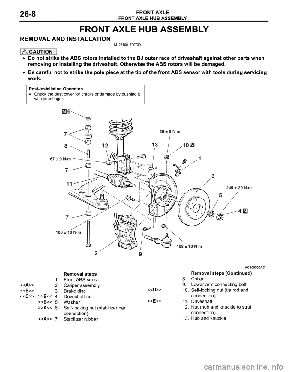
REMOVAL AND INSTALLATIONM1261001700739
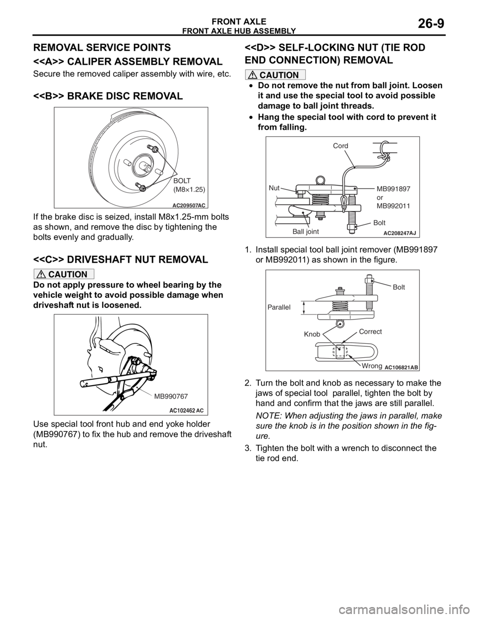
CAUTION
•Do not strike the ABS rotors installed to the BJ outer race of driveshaft against other parts when
removing or installing the driveshaft. Otherwise the ABS rotors will be damaged.
•
Post-installation Operation
•Check the dust cover for cracks or damage by pushing it
with your finger.
AC209505
N
N
N
5
4
3
1
8
10
9
2
7
6
167 ± 9 N·m 25 ± 5 N·m
108 ± 10 N·m 245 ± 29 N·m
100 ± 10 N·m
AC
7 7
11 12
13
Removal steps
1. Front ABS sensor
<> 2. Caliper assembly
<> 3. Brake disc
<
>>B<<5. Washer
>>A<<6.Self-locking nut (stabilizer bar
connection)
>>A<<7.Stabilizer rubber
8.Collar
9. Lower arm connecting bolt
<
connection)
<
12.Nut (hub and knuckle to strut
connection)
13.Hub and knuckle
Be careful not to strike the pole piece at the tip of the front ABS sensor with tools during servicing
work.
Removal steps (Continued)
Page 141 of 800
Page 142 of 800
FRONT AXLE HUB ASSEMBLY
FRONT AXLE26-10
<
AC100128
MB990241
MB990767
AG
AC303949
MB990244
(Three)
MB990767
MB990242
MB991354
AF
1.
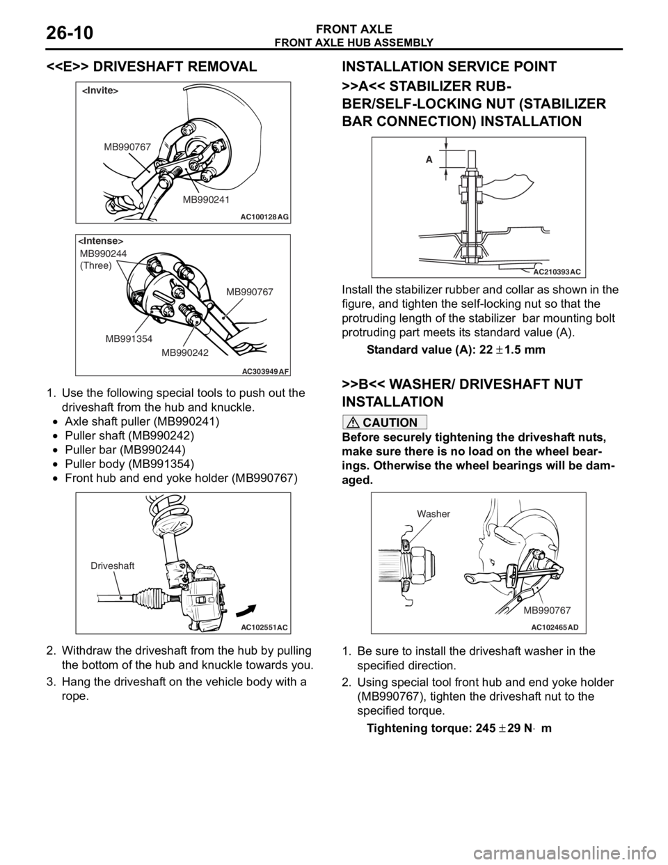
Use the fo llo wing special to ols to pu sh ou t the
driveshaf t from the hub an d kn uckle.
•Axle shaf t puller (MB9 90241 )
•Puller shaft (MB990 242)
•Puller bar (MB990 244)
•Puller body (MB99135 4)
•
AC102551
AC
Driveshaft
Front hub a nd end yoke holder (MB99076 7)
2.Withdraw th e driveshaf t from the hu b by pulling
th e botto m of the hub and knuckle towards you .
3.Hang the dr ive s haf t on the vehicle b ody with a
rope.
INST ALLA T ION SER VICE POINT
>>A<< STABILIZER RUB-
BER/SELF-LOCKING NUT (ST A BILIZER
BAR CONNECTION) INST
ALLA TION
AC210393AC
A
I
n st a ll the st a b ili zer rubb er an d coll ar as sho w n in t he
figure
, and t i ghte n the self-locking nut so tha t the
protruding length
of the st abilize r bar mount ing b o lt
protruding p
a rt meet s it s st and ard value (A).
St andard va lue (A): 22 ± 1.5 m m
>>B<< W A SHER/ DRIVESHAFT NUT
INST
ALLA TION
CAUTION
Before securely tightening the driveshaft nuts,
make sure there is no load on the wheel bear
-
ings. Otherwise the wheel bearings will be dam-
aged.
AC102465AD
MB990767
Washer
1. Be sure to install the driveshaft washer in the
specified direction.
2. Using special tool front hub and end yoke holder (MB990767), tighten the driveshaft nut to the
specified torque.
Tightening torque: 245 ± 29 N⋅m
Page 146 of 800
DRIVESHAFT ASSEMBLY
FRONT AXLE26-14
DRIVESHAFT ASSEMBLY
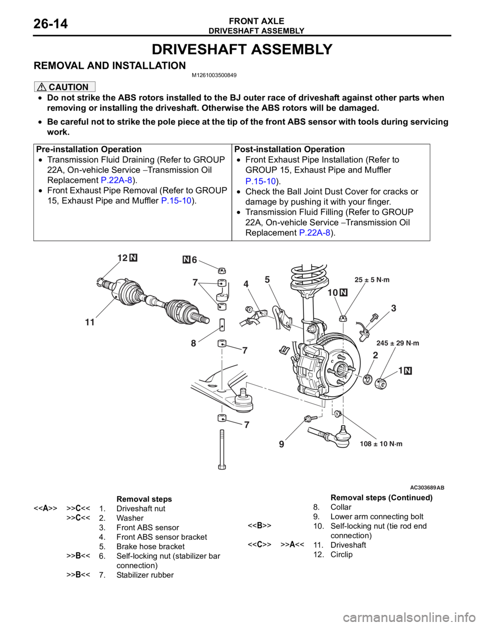
REMOVAL AND INSTALLATIONM1261003500849
CAUTION
•Do not strike the ABS rotors installed to the BJ outer race of driveshaft against other parts when
removing or installing the driveshaft. Otherwise the ABS rotors will be damaged.
•
Pre-installation Operation
•Transmission Fluid Draining (Refer to GROUP
22A, On-vehicle Service
− Transmission Oil
Replacement
P.22A-8).
•Front Exhaust Pipe Removal (Refer to GROUP
15, Exhaust Pipe and Muffler
P.15-10).
Post-installation Operation
•Front Exhaust Pipe Installation (Refer to
GROUP 15, Exhaust Pipe and Muffler
P.15-10).
•Check the Ball Joint Dust Cover for cracks or
damage by pushing it with your finger.
•Transmission Fluid Filling (Refer to GROUP
22A, On-vehicle Service
− Transmission Oil
Replacement
P.22A-8).
AC303689AB
9
N
N
NN
10
7
4
3
2 1
25 ± 5 N·m
245 ± 29 N·m
108 ± 10 N·m
8
5
6
11 12
77
Removal steps
<>>>C<<1.Driveshaft nut
>>C<<2.Washer
3.Front ABS sensor
4.Front ABS sensor bracket
5.Brake hose bracket
>>B<<6.Self-locking nut (stabilizer bar
connection)
>>B<<7.Stabilizer rubber
8.Collar
9.Lower arm connecting bolt
<>10.Self-locking nut (tie rod end
connection)
<
12.Circlip
Be careful not to strike the pole piece at the tip of the front ABS sensor with tools during servicing
work.
Removal steps (Continued)
Page 147 of 800
Page 148 of 800
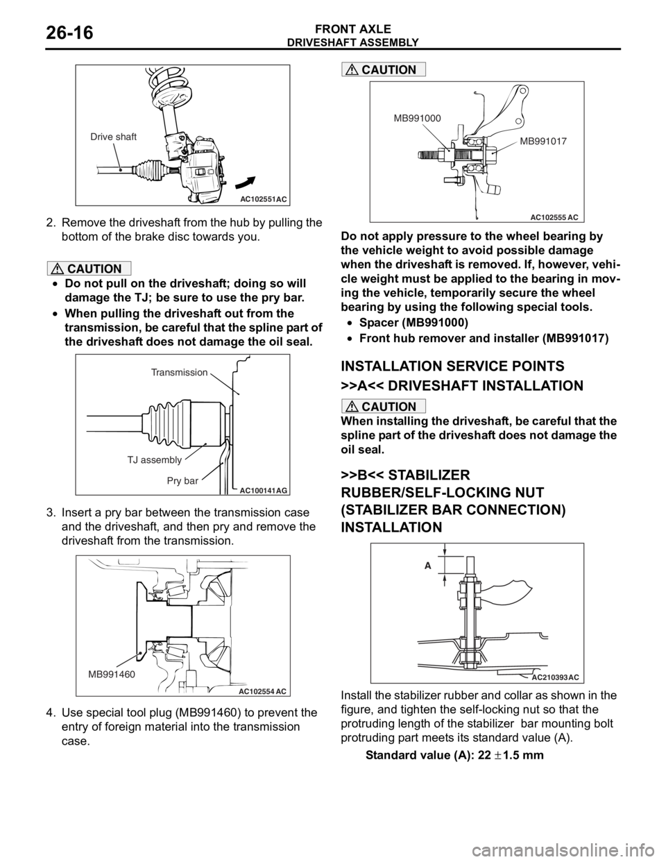
AC102551AC
Drive shaft
DRIVESHAFT ASSEMBL Y
FRONT AXLE26-16
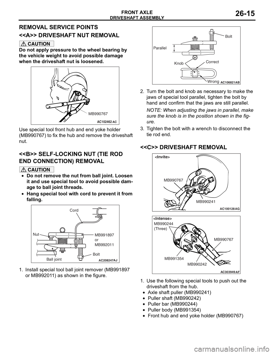
2.Remove th e dr ivesh a f t from th e h ub b y p u lling the
bo ttom of the brake disc toward s you.
CAUTION
•Do not pull on the driveshaft; doing so will
damage the TJ; be sure to use the pry bar.
•
AC100141
Transmission
TJ assembly Pry bar
AG
When pulling the driveshaft out from the
transmission, be careful that the spline part of
the driveshaft does not damage the oil seal.
3. Insert a pry bar between the transmission case and the driveshaft, and then pry and remove the
driveshaft from the transmission.
AC102554
MB991460
AC
4. Use special tool plug (MB991460) to prevent the
entry of foreign material into the transmission
case.
AC102555 AC
MB991017
MB991000
CAUTION
Do not apply pressure to the wheel bearing by
the vehicle weight to avoid possible damage
when the driveshaft is removed. If, however, vehi
-
cle weight must be applied to the bearing in mov-
ing the vehicle, temporarily secure the wheel
bearing by using the following special tools.
•Spacer (MB991000)
•Front hub remover and installer (MB991017)
INSTALLATION SERVICE POINTS
>>A<< DRIVESHAFT INSTALLATION
CAUTION
When installing the driveshaft, be careful that the
spline part of the driveshaft does not damage the
oil seal.
>>B<< STABILIZER
RUBBER/SELF-LOCKING NUT
(STABILIZER BAR CONNECTION)
INSTALLATION
AC210393
AC
A
Install the stabilizer rubber and collar as shown in the
figure, and tighten the self-locking nut so that the
protruding length of the stabilizer bar mounting bolt
protruding part meets its standard value (A).
Standard value (A): 22 ± 1.5 mm