wheel torque MITSUBISHI LANCER IX 2006 User Guide
[x] Cancel search | Manufacturer: MITSUBISHI, Model Year: 2006, Model line: LANCER IX, Model: MITSUBISHI LANCER IX 2006Pages: 800, PDF Size: 45.03 MB
Page 185 of 800

SERVICE SPECIFICATIONS
FRONT SUSPENSION33-3
SERVICE SPECIFICATIONS
M1332000300746
ItemStandard value
Toe-inAt the centre of tyre tread mm1 ± 2
Toe-angle (per wheel)0°03' ± 0°06'
Toe-out angle on turns (inner wheel when outer wheel at 20°)21°42' ± 1°30'
Steering angleInner wheelInvite39°30' ± 1°30'
Intense (LH drive vehicles)33°40' +1°00'/−2°00'
Intense (RH drive vehicles)37°00' +1°00'/−2°00'
Outer wheel (reference)Invite32°30'
Intense (LH drive vehicles)28°46'
Intense (RH drive vehicles)30°00'
CamberInvite0°05' ± 0°30'*
Intense−0°05' ± 0°30'*
CasterInvite2°45' ± 0°30'*
Intense2°55' ± 0°30'*
Kingpin inclinationInvite12°30' ± 1°30'
Intense12°40' ± 1°30'
Lower arm ball joint starting torque N⋅m0 − 3.9
Protruding length of stabilizer link thread part mm22 ± 1.5
NOTE: *: Difference between right and left wheels must be less than 30'
LUBRICANT
M1332000400152
ItemSpecified lubricantQuantity
Lower arm ball jointLip portion of ball joint coverMultipurpose grease SAE J310,
NLGI No.2 or equivalentAs required
Inside of ball joint cover
Page 186 of 800
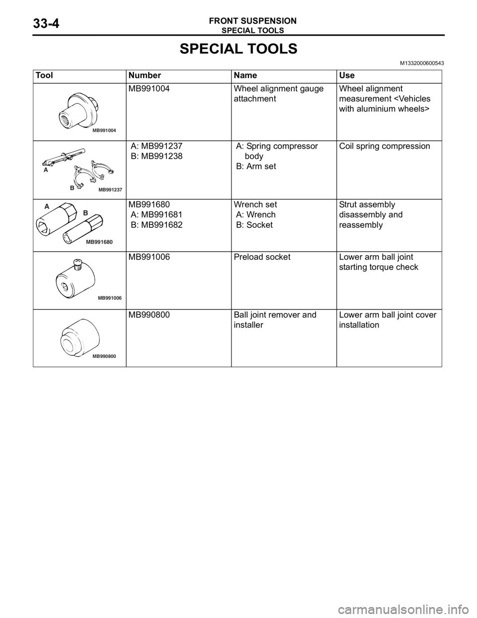
SPECIAL TOOLS
FRONT SUSPENSION33-4
SPECIAL TOOLS
M1332000600543
ToolNumberNameUse
MB991004
MB991004Wheel alignme n t gau ge
att
a chmentWheel alig nme n t
measurement
with aluminium wheels>
MB991237
A
B
A: MB9912 37
B: MB991238
A: Sp ring compressor
b ody
B: Arm set
Coil spring compression
MB991680
A BMB991680
A: MB9916 81
B: MB991682
Wr ench set
A: W r ench
B: Socket
Str u t a s s e m b l y
d
i sa ssembly an d
reassembly
MB991006
MB991006Prel oad socketLo wer arm ball joint
st
arting torque check
MB990800
MB990800Ball j o int remo ver an d
inst
al lerLo wer arm ball joint cover
inst
allation
Page 188 of 800
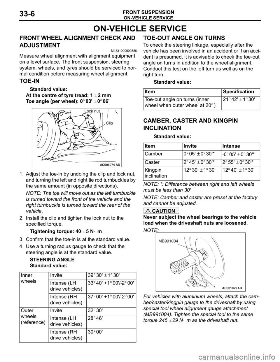
ON-VEHICLE SERVICE
FRONT SUSPENSION33-6
ON-VEHICLE SERVICE
FRONT WHEEL ALIGNMENT CHECK AND
ADJUSTMENT
M1331000900886
Measure wheel alignment with alignment equipment
on a level surface. The front suspension, steering
system, wheels, and tyres should be serviced to nor
-
mal condition before measuring wheel alignment.
TOE-IN
Standard value:
At the centre of tyre tread: 1 ± 2 mm
Toe angle (per wheel): 0°03' ± 0°06'
AC006074 AD
Lock nut
Clip
1.Adjust the to e-in by undoing th e clip and lock nut,
and turning th e lef t and rig h t tie rod turnbu ckles by
th e same amount (in op posite direct ions).
NOTE: The toe will move out as th e lef t turnbuckle
is turn
ed toward the fro n t of th e ve hicle an d the
right tu
rnbuckle is turned t o ward the rear of the
vehicle.
2. In st all the clip and tighten the lock nut to the
specifie d torqu e .
Ti ghte n ing torque: 40 ± 5 N⋅m
3.Conf irm t hat the toe-in is at the st anda rd value.
4.Use a turn ing ra dius gaug e to check tha t the
steering ang le is at the st an dard value .
STEE R I N G AN G L E
St andard va lue:
Inner
wheelsInvite39°30' ± 1°30'
Intense (LH
drive vehicles)33°40' +1°00'/−2°00'
Intense (RH
drive vehicles)37°00' +1°00'/−2°00'
Outer
wheels
(reference)Invite32°30'
Intense (LH
drive vehicles)28°46'
Intense (RH
drive vehicles)30°00'
TO E-OUT ANGLE ON TURNS
To check the stee ring linkage, e s pe cially af ter the
vehicle has been invo
lve d in an accid ent or if an a cci
-
dent is pres umed, it is advisab le to check th e toe-ou t
angle
on tu rns in addition to the wh eel a lig nmen t.
Conduct this test on th e lef t tu rn as we ll a s on the
right turn.
St andard va lue:
ItemSpecification
Toe-out angle on turns (inner
wheel when outer wheel at 20
°)
21°42' ± 1°30'
CAMBER, CASTER AND KINGPIN
INCLINA
T ION
St andard va lue:
ItemInviteIntense
Camber0°05' ± 0°30'*−0°05' ± 0°30'*
Caster2°45' ± 0°30'*2°55' ± 0°30'*
Kingpin
inclination12°30' ± 1°30'12°40' ± 1°30'
NOTE: *: Diffe rence between right and lef t wheels
must be less than 30'
NOTE: Camber and caster are prese t at th e factory
and cannot be adjust ed.
CAUTION
Never subject the wheel bearings to the vehicle
load when the driveshaft nuts are loosened.
NOTE:
AC001079
MB991004
AB
For vehicles with aluminium wheels, attach the cam-
ber/caster/kingpin gauge to the driveshaft by using
special tool wheel alignment gauge attachment
(MB991004). Tighten the special tool to the same
torque 245
± 29 N⋅m as the driveshaft nut.
Page 201 of 800

SERVICE SPECIFICATIONS
REAR SUSPENSION34-3
SPECIFICATION
COIL SPRING
ItemSedanWagon
InviteIntenseInviteIntense
Wire diameter mm10101010
Average diameter mm78 − 9078 − 9078 − 9078 − 90
Free length mm359331377368
SERVICE SPECIFICATIONS
M1341000300733
ItemStandard value
Camber (Difference between right and left within 30') −0°40' ± 0°30'
Toe-inAt the centre of tyre tread mm3 ± 2
Toe-angle (per wheel)0°08' ± 0°05'
Thrust angle0°00' ± 0°09'
Control link pillow ball bushing starting torque
Upper arm pillow ball bushing starting torque
Lower arm pillow ball bushing starting torque N⋅m0.5 − 3.0
Protruding length of stabilizer link bolt mm6 − 8
Stabilizer link ball joint continuous turning torque N⋅m0.5 − 1.5
LUBRICANT
M1341000400172
ItemSpecified lubricantQuantity
Stabilizer link ball joint (inside of dust cover)Multipurpose grease SAE J310, NLGI No.2
or equivalentAs required
Page 202 of 800
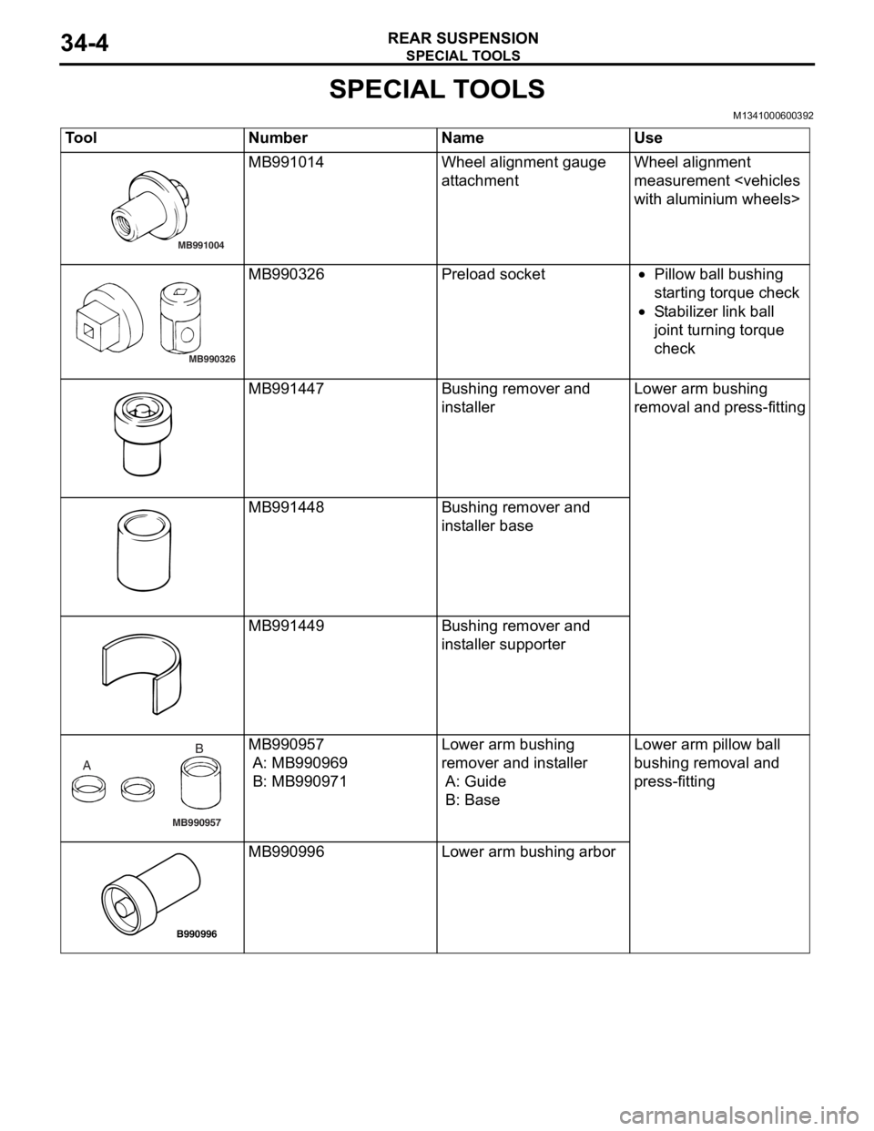
SPECIAL TOOLS
REAR SUSPENSION34-4
SPECIAL TOOLS
M1341000600392
ToolNumberNameUse
MB991004
MB991014Wheel alignme n t gau ge
att
a chmentWheel alig nme n t
measurement
MB990326
MB990326Prel oad socket•Pillow ba ll b u shing
st
a r ting t o rque check
•St abil i ze r lin k ba ll
joint t
u rnin g torque
check
MB991447Bushing remove r and
inst
al lerLo wer arm bushing
re
moval and press-fit t ing
MB991448Bushing remove r and
inst
al ler b a se
MB991449Bushing remove r and
inst
aller suppo rter
MB990957
A B
MB990
957
A: MB9909 69
B: MB990971
Lower arm bushing
remover an
d inst a lle r
A: Guide
B: Base
Lo wer arm pillow ball
b
u shing removal an d
p
r ess-fitting
B990996
MB990 996Lower arm bushing arbor
Page 204 of 800
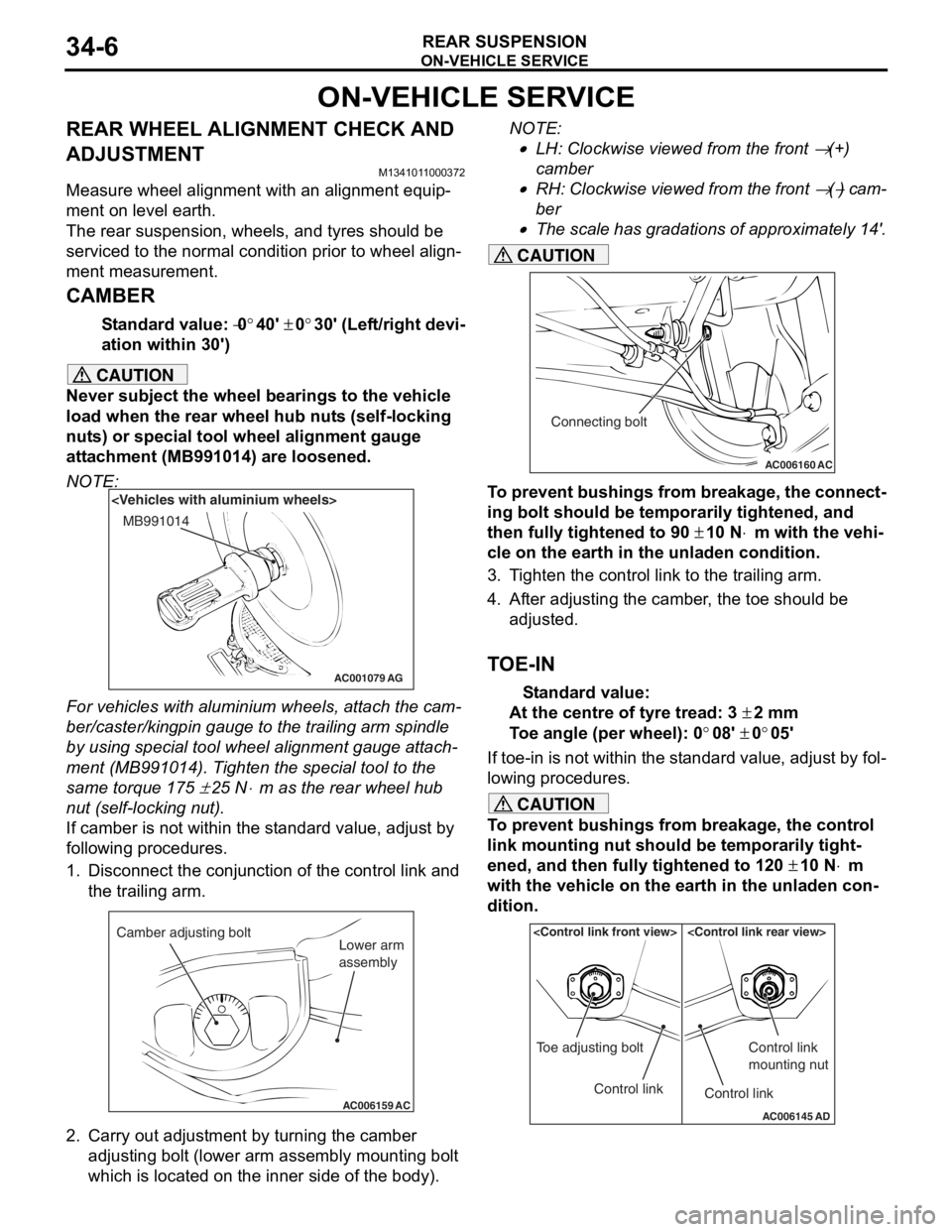
ON-VEHICLE SERVICE
REAR SUSPENSION34-6
ON-VEHICLE SERVICE
REAR WHEEL ALIGNMENT CHECK AND
ADJUSTMENT
M1341011000372
Measure wheel alignment with an alignment equip-
ment on level earth.
The rear suspension, wheels, and tyres should be
serviced to the normal condition prior to wheel align
-
ment measurement.
CAMBER
Standard value: −0°40' ± 0°30' (Left/right devi-
ation within 30')
CAUTION
Never subject the wheel bearings to the vehicle
load when the rear wheel hub nuts (self-locking
nuts) or special tool wheel alignment gauge
attachment (MB991014) are loosened.
NOTE:
AC001079
MB991014
AG
For vehicles with aluminium wheels, attach the cam-
ber/caster/kingpin gauge to the trailing arm spindle
by using special tool wheel alignment gauge attach
-
ment (MB991014). Tighten the special tool to the
same torque 175
± 25 N⋅m as the rear wheel hub
nut (self-locking nut).
If camber is not within the standard value, adjust by
following procedures.
1. Disconnect the conjunction of the control link and the trailing arm.
AC006159 AC
Camber adjusting bolt
Lower arm
assembly
2. Carry out adjustment by turning the camber
adjusting bolt (lower arm assembly mounting bolt
which is located on the inner side of the body).
NOTE: .
•LH: Clockwise viewed from the front → (+)
camber
•RH: Clockwise viewed from the front → (−) cam-
ber
•
AC006160 AC
Connecting bolt
The scale has gradations of approximately 14'.
CAUTION
To prevent bushings from breakage, the connect-
ing bolt should be temporarily tightened, and
then fully tightened to 90
± 10 N⋅m with the vehi-
cle on the earth in the unladen condition.
3. Tighten the control link to the trailing arm.
4. After adjusting the camber, the toe should be
adjusted.
TOE-IN
Standard value:
At the centre of tyre tread: 3 ± 2 mm
Toe angle (per wheel): 0°08' ± 0°05'
If toe-in is not within the standard value, adjust by fol-
lowing procedures.
CAUTION
To prevent bushings from breakage, the control
link mounting nut should be temporarily tight
-
ened, and then fully tightened to 120 ± 10 N⋅m
with the vehicle on the earth in the unladen con
-
dition.
AC006145 AD
Control link
Toe adjusting boltControl link
Control link
mounting nut
Page 231 of 800
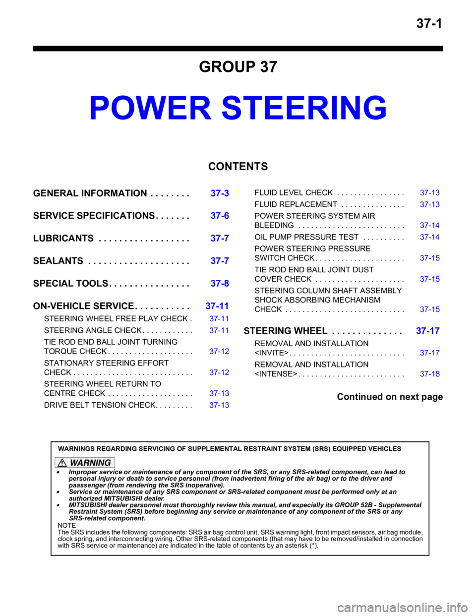
37-1
GROUP 37
POWER STEERING
CONTENTS
GENERAL INFORMATION . . . . . . . .37-3
SERVICE SPECIFICATIONS . . . . . . .37-6
LUBRICANTS . . . . . . . . . . . . . . . . . .37-7
SEALANTS . . . . . . . . . . . . . . . . . . . .37-7
SPECIAL TOOLS . . . . . . . . . . . . . . . .37-8
ON-VEHICLE SERVICE . . . . . . . . . . .37-11
STEERING WHEEL FREE PLAY CHECK . 37-11
STEERING ANGLE CHECK . . . . . . . . . . . . 37-11
TIE ROD END BALL JOINT TURNING
TORQUE CHECK . . . . . . . . . . . . . . . . . . . . 37-12
STATIONARY STEERING EFFORT
CHECK . . . . . . . . . . . . . . . . . . . . . . . . . . . . 37-12
STEERING WHEEL RETURN TO
CENTRE CHECK . . . . . . . . . . . . . . . . . . . . 37-13
DRIVE BELT TENSION CHECK. . . . . . . . . 37-13
FLUID LEVEL CHECK . . . . . . . . . . . . . . . . 37-13
FLUID REPLACEMENT . . . . . . . . . . . . . . . 37-13
POWER STEERING SYSTEM AIR
BLEEDING . . . . . . . . . . . . . . . . . . . . . . . . . 37-14
OIL PUMP PRESSURE TEST . . . . . . . . . . 37-14
POWER STEERING PRESSURE
SWITCH CHECK . . . . . . . . . . . . . . . . . . . . . 37-15
TIE ROD END BALL JOINT DUST
COVER CHECK . . . . . . . . . . . . . . . . . . . . . 37-15
STEERING COLUMN SHAFT ASSEMBLY
SHOCK ABSORBING MECHANISM
CHECK . . . . . . . . . . . . . . . . . . . . . . . . . . . . 37-15
STEERING WHEEL . . . . . . . . . . . . . .37-17
REMOVAL AND INSTALLATION
REMOVAL AND INSTALLATION
Continued on next page
WARNINGS REGARDING SERVICING OF SUPPLEMENTAL RESTRAINT SYSTEM (SRS) EQUIPPED VEHICLES
WARNING
•Improper service or maintenance of any component of the SRS, or any SRS-related component, can lead to
personal injury or death to service personnel (from inad vertent firing of the air bag) or to the driver and
paassenger (from renderin g the SRS inoperative).
•Service or maintenance of any SRS component or SRS-related component must be performed only at an
authorized MITSUBISHI dealer.
•MITSUBISHI dealer personnel must thoroughly review th is manual, and especially its GROUP 52B - Supplemental
Restraint System (SRS) before begi nning any service or maintenance of any component of the SRS or any
SRS-related component.
NOTE
The SRS includes the following components: SRS air bag control unit, SRS warning light, front impact sensors, air bag module,
clock spring, and interconnecting wiring. Other SRS-related components (that may have to be removed/installed in connection
with SRS service or maintenance) are indicated in the table of contents by an asterisk (*).
Page 236 of 800

SERVICE SPECIFICATIONS
POWER STEERING37-6
SERVICE SPECIFICATIONS
M1372000300795
ItemStandard valueLimit
Steering wheel free
play mmWith engine running−30
With engine stopped10 or less−
Steering angleInner wheelInvite39°30' ± 1°30'−
Intense (LH drive vehicles)33°40' +1°00'/-2°00'−
Intense (RH drive vehicles)37°00' +1°00'/-2°00'−
Outer wheel
(reference)Invite32°30'−
Intense (LH drive vehicles)28°46'−
Intense (RH drive vehicles)30°00'−
Toe-inAt the centre of tyre tread mm1 ± 2−
Toe-angle (per wheel)0°03' ± 06'−
Tie rod end ball joint turning torque N⋅m0.5 − 2.5−
Tie rod swing resistance N [Tie rod swing torque N⋅m]8 − 27 [1.5 − 4.9]−
Stationary steering effort N [Fluctuation allowance N]29 or less [5.9 or less]−
Oil pump pressure
MPa (750
± 100 r/min.)
Oil pump relief pressure8.8 − 9.5−
Pressure under no-load conditions0.2 − 0.7−
Steering gear retention hydraulic pressure8.8 − 9.5−
Oil pressure switch operating pressure
MPaOFF → ON1.5 − 2.0−
ON → OFF0.7 − 2.0−
Steering gear total pinion torque N⋅m
[Change in torque N
⋅m]
Invite0.8 − 2.1 [0.6 or less]−
Intense0.7 − 2.1 [0.6 or less]−
Opening dimension of special tool boot band crimping tool (MB991561)
mm2.9−
Band crimped width mm2.4 − 2.8−
Page 241 of 800
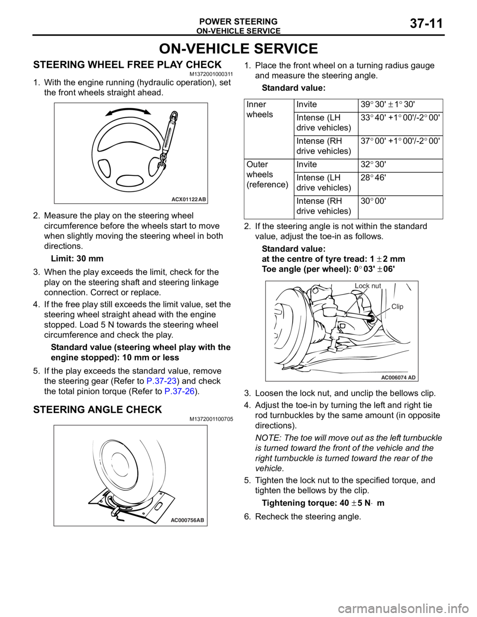
ON-VEHICLE SERVICE
POWER STEERING37-11
ON-VEHICLE SERVICE
STEERING WHEEL FREE PLAY CHECKM1372001000311
1. With the engine running (hydraulic operation), set the front wheels straight ahead.
ACX01122 AB
2.Measure the play on th e ste e ring wh eel
circumfer ence before the whee ls st a r t to move
when slightly moving the stee ring whe e l in both
direct ions.
Limit: 30 mm
3.Wh en the play exceed s the limit, check fo r the
play on the stee ring shaf t and stee ring linkage
connectio n . Correct or replace .
4.If th e free play still exceeds the limit valu e, set t he
steering wheel stra ight ahead with the engine
stoppe d. Loa d 5 N towards the steer ing whee l
circumfer ence and check the play .
St andard value (steering whee l pla y with the
engine s
t opped): 1 0 mm o r l ess
5.If the play e xce eds the st an dard value , remove
th e ste e ring gear (Refe r to
P.37-23) and check
the tot a l p i nion torqu e (Refer to P.37-26).
STEERING ANGLE CHECKM137200 1 1 0070 5
AC000756AB
1.Place t he fron t wh eel on a tu rning radiu s gau ge
a nd me asure the steering ang le.
St andard va lue:
Inner
wheelsInvite39°30' ± 1°30'
Intense (LH
drive vehicles)33°40' +1°00'/-2°00'
Intense (RH
drive vehicles)37°00' +1°00'/-2°00'
Outer
wheels
(reference)Invite32°30'
Intense (LH
drive vehicles)28°46'
Intense (RH
drive vehicles)30°00'
2.If the steerin g ang le is not within the st a ndard
value , adjust t he toe-in as follows.
St andard va lue:
at the centre of tyre trea d: 1 ± 2 mm
To e angle (p er whee l): 0°03' ± 06'
AC006074 AD
Lock nut
Clip
3.L oose n the lock nut, and un clip the bellows clip .
4.Adjust the toe - in by turning th e lef t an d righ t tie
ro d turnb u ckles by th e sa me a m oun t (in o pposite
directions).
NOTE: The to e will move out as th e lef t turnbuckle
is tur
ned toward the fro n t of th e ve hicle an d the
right tu
rnbuckle is turned toward the rear of the
vehicle.
5. T i ghten the lo ck nut to the specified torque , and
tighten the be llo ws by the clip .
Ti ghte n ing torque: 40 ± 5 N⋅m
6.Recheck the stee ring a ngle .
Page 242 of 800
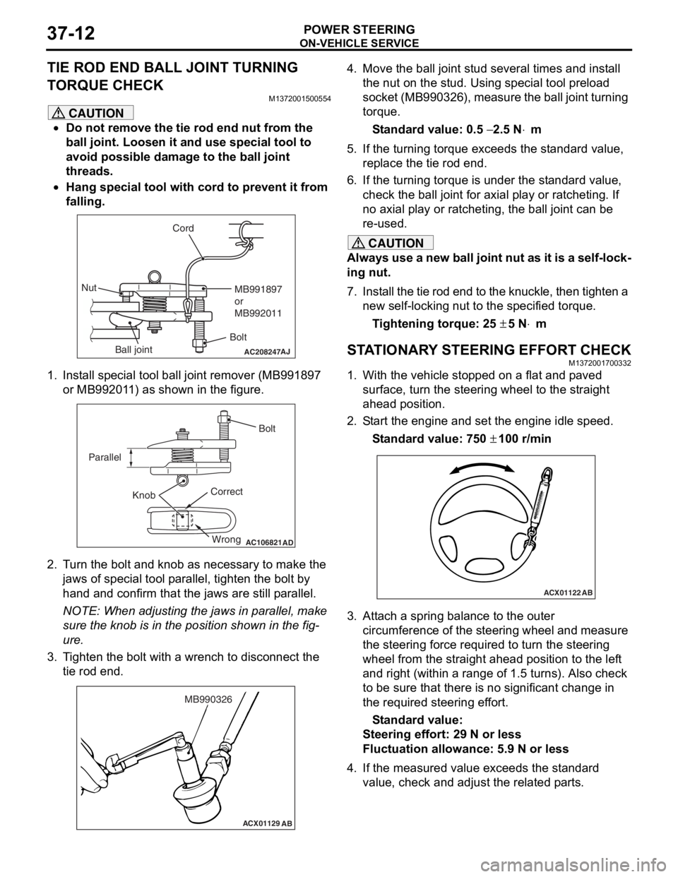
ON-VEHICLE SERVICE
POWER STEERING37-12
TIE ROD END BALL JOINT TURNING
TORQUE CHECK
M1372001500554
CAUTION
•Do not remove the tie rod end nut from the
ball joint. Loosen it and use special tool to
avoid possible damage to the ball joint
threads.
•
AC208247AJ
CordBoltMB991897
or
MB992011
Nut
Ball joint
Hang special tool with cord to prevent it from
falling.
1. Install special tool ball joint remover (MB991897 or MB992011) as shown in the figure.
AC106821
Knob
Parallel
Bolt
Correct Wrong
AD
2. Turn the bolt and knob as necessary to make the jaws of special tool parallel, tighten the bolt by
hand and confirm that the jaws are still parallel.
NOTE: When adjusting the jaws in parallel, make
sure the knob is in the position shown in the fig
-
ure.
3. Tighten the bolt with a wrench to disconnect the tie rod end.
ACX01129 AB
MB990326
4. Move the ball joint stud several times and install
the nut on the stud. Using special tool preload
socket (MB990326), measure the ball joint turning
torque.
Standard value: 0.5 − 2.5 N⋅m
5. If the turning torque exceeds the standard value, replace the tie rod end.
6. If the turning torque is under the standard value, check the ball joint for axial play or ratcheting. If
no axial play or ratcheting, the ball joint can be
re-used.
CAUTION
Always use a new ball joint nut as it is a self-lock-
ing nut.
7. Install the tie rod end to the knuckle, then tighten a new self-locking nut to the specified torque.
Tightening torque: 25 ± 5 N⋅m
STATIONARY STEERING EFFORT CHECKM1372001700332
1. With the vehicle stopped on a flat and paved
surface, turn the steering wheel to the straight
ahead position.
2. Start the engine and set the engine idle speed.
Standard value: 750 ± 100 r/min
ACX01122 AB
3. Attach a spring balance to the outer
circumference of the steering wheel and measure
the steering force required to turn the steering
wheel from the straight ahead position to the left
and right (within a range of 1.5 turns). Also check
to be sure that there is no significant change in
the required steering effort.
Standard value:
Steering effort: 29 N or less
Fluctuation allowance: 5.9 N or less
4. If the measured value exceeds the standard value, check and adjust the related parts.