check MITSUBISHI LANCER IX 2006 Workshop Manual
[x] Cancel search | Manufacturer: MITSUBISHI, Model Year: 2006, Model line: LANCER IX, Model: MITSUBISHI LANCER IX 2006Pages: 800, PDF Size: 45.03 MB
Page 118 of 800
Battery voltageNormal condition
AppliedVacuum leaks
Not appliedVacuum maintained
EMISSION CONTROL
ENGINE AND EMISSION CONTROL17-12
5. Measure the resistance between the terminals of the solenoid valve.
Standard value: 30 − 34 Ω (at 20°C)
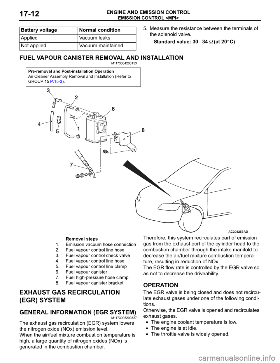
FUEL VAPOUR CANISTER RE MOVAL AND INSTALLATION
M1173004200153
Pre-removal and Post-installation Operation
Air Cleaner Assembly Removal and Installation (Refer to
GROUP 15
P.15-3).
AC208253
1
2
3
4 5 6
7 8
AD
Removal steps
1.Emission vacuum hose connection
2.Fuel vapour control line hose
3.Fuel vapour control check valve
4.Fuel vapour control line hose
5.Fuel vapour control line clamp
6.Fuel vapour canister
7.Fuel high-pressure hose clamp
8.Fuel vapour canister bracket
EXHAUST GAS RECIRCULA
T ION
(EGR) SYSTEM
GENERAL INFORMAT ION (EGR SYSTEM)
M1173 0052 0032 7
The exhaust gas recircu l atio n (EGR) system lowers
the nitrogen
oxide (NOx) emission level.
When the air/fuel mixture combus tio n temp erature is
high,
a larg e qua ntity of nitrogen oxides (NOx) is
generat
ed in the comb ustion chamb e r .
Therefor e, this syst em re circulat es p a rt o f emission
gas fro
m the e x ha ust po rt of the cylinder h ead to th e
combust
i on chamber thro ugh th e int a ke ma nifold to
decre
ase the air/fuel mixture combust i on te mpera
-
ture, resulting in redu ctio n of NOx.
The EGR flow rate is cont rolle d by the EGR valve so
as no
t to de crease the driveability .
OPERAT ION
The EGR valve is being clos ed an d does not re circu-
late ex hau st ga ses unde r one o f the fo llo wing condi-
tions.
Otherwise, th e EGR va lve is opene d an d recircul ates
exha
ust g a ses.
•The engine coolan t temperature is low .
•The engine is at idle.
•The throttle va lve is widely ope ned.
Page 121 of 800
EMISSION CONTROL
ENGINE AND EMISSION CONTROL17-15
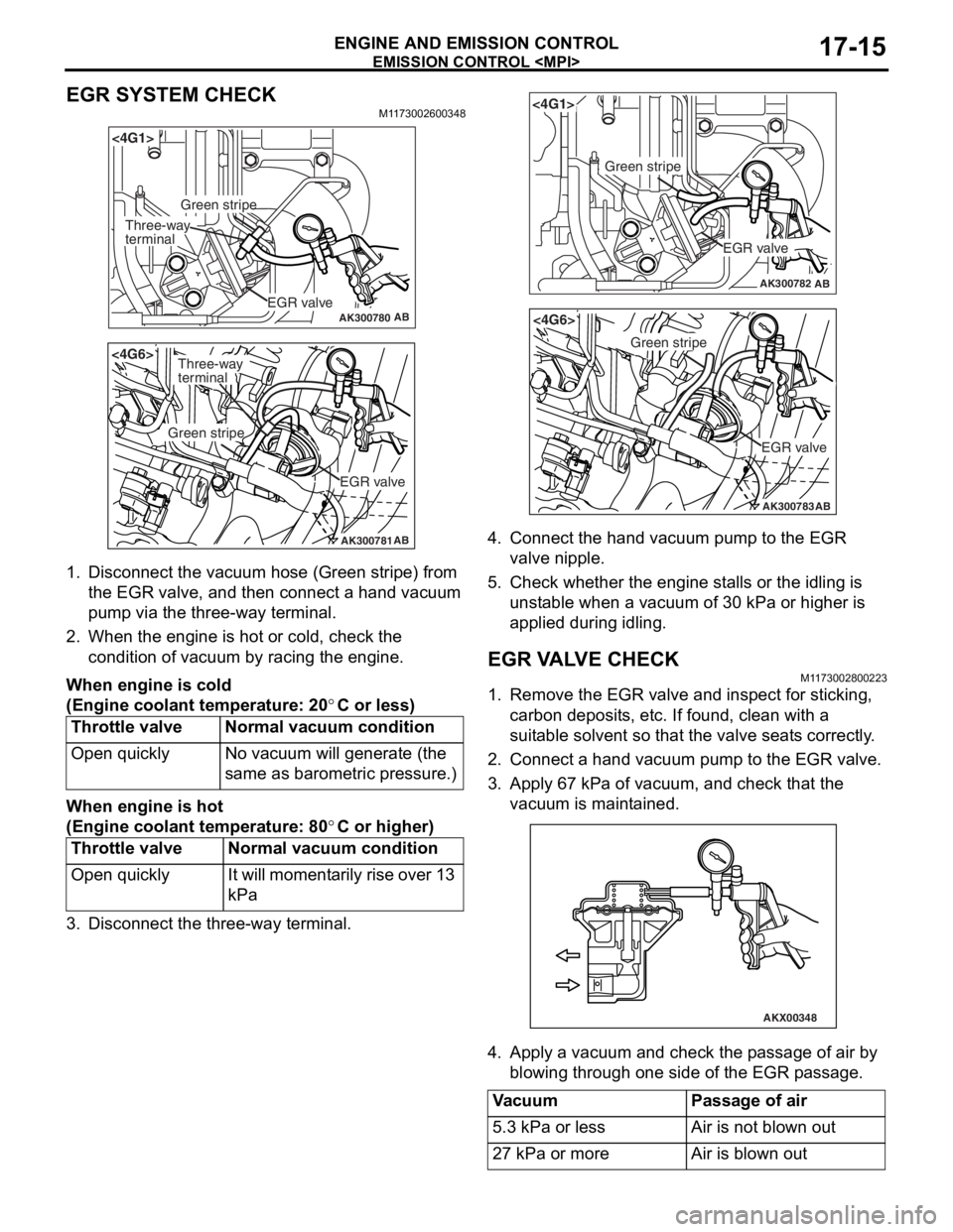
EGR SYSTEM CHECK
M1173002600348
AK300780AB
<4G1>
EGR valve
Green stripe
Three-way
terminal
AK300781AB
<4G6>
EGR valve
Green stripe
Three-way
terminal
1.Disco nnect the vacu um ho se (Green stripe) from
th e EGR valve, a nd th en connect a hand vacuum
pu mp via t he thre e-way te rmin al.
2.Wh en the engine is hot o r cold, check the
condition of va cuum by racing the engine.
When engine is c o ld
(Eng ine coo lant tem perature: 20°C or less)
Throttle valveNormal vacuum co ndition
Open quicklyNo va cuum will gene rate (th e
same as baro
m etric pre s sure.)
When engine is h o t
(Eng ine coo lant tem perature: 80°C or higher)
Throttle valveNormal vacuum c ondition
Open quicklyIt will mo me nt a r i l y rise o v er 13
kPa
3.Disco nnect the th ree-way t e rminal.
AK300782AB
<4G1>
EGR valve
Green stripe
AK300783AB
<4G6>
EGR valve
Green stripe
4.Conn ect the han d va cuum pump to t he EGR
valve nipple.
5.Check whe t her th e engine st alls or the idling is
u n st able when a vacuum of 30 kPa or h i gher is
a pplied during idling.
EGR V A L V E CHECKM1173 0028 0022 3
1.Remove the EGR valve an d inspect for stickin g ,
carbon deposit s, e t c. If found , clean with a
suit able so lve n t so that th e va lve seat s corre ctly .
2.Conn ect a hand vacuum pump to the EGR va lve .
3.App l y 6 7 kPa of va cuum, and check t hat the
vacu um is maint a ined.
AKX00348
4.App l y a vacuum and chec k th e p a ssage of air by
b l owing throug h one side of the EGR p a ssage.
VacuumPassage of air
5.3 kPa or lessAir is not blown out
27 kPa or moreAir is blown out
Page 122 of 800
EMISSION CONTROL
ENGINE AND EMISSION CONTROL17-16
5. Replace the gasket, and tighten to the specified torque.
Tightening torque:
<4G1> 21 ± 4 N⋅m
<4G6> 20 ± 2 N⋅m
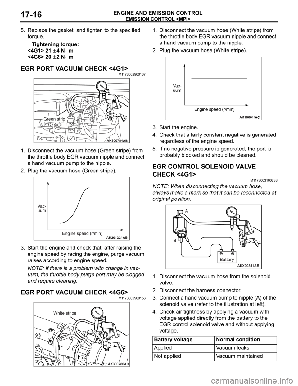
EGR PORT VACUUM CHECK <4G1>M1173002900167
AK300784AB
Green strip
1.Disco nnect the vacu um ho se (Green stripe) from
th e t h ro tt le b o d y EGR va cuu m ni pp le an d co nn ec t
a hand vacu um p u mp to the nipple.
2.Plu g the vacuum hose (Gree n stripe).
AK201224AB
Vac-
uum
Engine speed (r/min)
3.S t art the engin e and check t hat, af ter ra ising th e
engine spe ed by ra cin g the e ngine, p u rge vacuu m
raises according to engine speed.
NOTE: If ther e is a prob lem with change in vac-
uum, the t h rottle bod y p u rge port may be clo gged
an
d requ ire clean ing.
EGR PORT VA CUUM CHECK <4G6>M1173 0029 0015 6
AK300786AB
White stripe
1.Disco nnect the vacu um h o se (W hite strip e ) from
th e t h ro tt le b o d y EGR va cuu m ni pp le an d co nn ec t
a hand vacuum p u mp to the nipple.
2.Plug the vacuum hose (White stripe).
AK100011AC
Vac-
uum
Engine speed (r/min)
3.S t art the engine.
4.Check that a fairly const a nt n egative is gene rated
re gardle s s of the engine sp eed.
5.If no neg ative pressur e is genera t ed, th e port is
p r obably blocked an d sh ould be cleane d.
EGR CONTROL SOLENOID VA L V E
CHECK <
4 G1 >
M1173 0031 0023 8
NOTE: Whe n discon nect i ng th e va cuum hose,
always make a mark so th at it can be reconnected at
original p o sition.
AKX00351
A
B
AE
Battery
1. Disco nnect the vacu um h o se f r om th e solenoid
valve.
2.Disco nnect the ha rness connector .
3.Con nect a ha nd vacu um pump to nipp le (A) of the
solen o id valve (ref e r to th e ill ust r ation at le f t ).
4.Check a i r tightness b y ap plying a vacuum with
volt age applied d i rectly from t he batt e ry to the
EGR cont rol solen o id valve and withou t applyin g
volt age .
Battery voltageNormal condition
AppliedVa c u u m l e a k s
Not appliedVacuum maintained
Page 123 of 800

AKX00352
EMISSI ON CONTROL
ENGINE AND E M ISSION CON T R O L17-17
5.Measure the resist ance between the te rmin als of
th e solenoid va lve .
St andard va lue: 29 − 35 Ω (at 20°C)
EGR CONTROL SOLENOID V A L V E
CHECK <
4 G6>
M1173 0031 0024 9
NOTE: Whe n discon nect i ng th e va cuum hose,
always
make a mark so th at it can be reconnected at
original p o sition.
AK201251AB
A
B
C
Battery
1.Disco nnect the vacu um h o se f r om th e solenoid
valve.
2.Disco nnect the ha rness connector .
3.Con nect a ha nd vacu um pump to nipp le (A) of the
solen o id valve (ref e r to th e ill ust r ation at le f t ).
4.Check a i r tightness b y ap plying a vacuum with
volt age applied d i rectly from t he batt e ry to the
EGR cont rol solen o id valve and withou t applyin g
volt age .
Battery
voltageB nipple
conditionNormal condition
Not appliedOpenVacuum
maintained
AppliedOpenVacuum leaks
ClosedVacuum
maintained
AK100016
5.Measure the resist ance betwee n the te rminals of
th e so lenoid valve .
St andard va lue: 29 − 35 Ω (at 20°C)
Page 133 of 800
26-1
GROUP 26
FRONT AXLE
CONTENTS
GENERAL INFORMATION . . . . . . . .26-2
SERVICE SPECIFICATIONS . . . . . . .26-3
LUBRICANTS . . . . . . . . . . . . . . . . . .26-3
SPECIAL TOOLS . . . . . . . . . . . . . . . .26-4
ON-VEHICLE SERVICE . . . . . . . . . . .26-7
WHEEL BEARING AXIAL PLAY CHECK . . 26-7
HUB BOLT REPLACEMENT . . . . . . . . . . . 26-7
FRONT AXLE HUB ASSEMBLY . . . .26-8
REMOVAL AND INSTALLATION . . . . . . . . 26-8
INSPECTION. . . . . . . . . . . . . . . . . . . . . . . . 26-11
DISASSEMBLY AND REASSEMBLY . . . . . 26-11
INSPECTION. . . . . . . . . . . . . . . . . . . . . . . . 26-13
DRIVESHAFT ASSEMBLY. . . . . . . . .26-14
REMOVAL AND INSTALLATION . . . . . . . . 26-14
DISASSEMBLY AND REASSEMBLY . . . . . 26-18
INSPECTION. . . . . . . . . . . . . . . . . . . . . . . . 26-21
BJ BOOT (RESIN BOOT)
REPLACEMENT . . . . . . . . . . . . . . . . . . . . . 26-21
Page 139 of 800

ON-VEHICLE SERVICE
FRONT AXLE26-7
ON-VEHICLE SERVICE
WHEEL BEARING AXIAL PLAY CHECKM1261000900224
1. Remove the caliper assembly and suspend it with a wire.
2. Remove the brake disc from the front hub.
AC209503 AC
3.
Att a ch a dial ga uge a s sh own in the illustration,
an d th en measure the axial play while moving the
hu b in the axial dire ctio n.
Limit: 0.05 mm
4.If axial play e x ceeds t he limit, disassemble the
fro n t hub assemb ly a nd check the p a rt s.
5.In st all the bra k e d i sc, ca lipe r assembly and
tighten th e caliper assemb ly mount ing bolt s to the
specifie d torqu e 100
± 10 N⋅m.
HUB BOL T REPLACEMENTM12610010 0029 1
1.Remove the ca lip er assembly a nd suspe nd it wit h
wire so t hat it does not fa ll.
2.Remove the bra k e d i sc.
AC302114
MB991618
AD
Hub bolt
3.Use spe c ia l too l hub bolt remover (MB99161 8) to
re move the h ub bo lt s.
AC104588
MB990767
Plain
washer
AC
4. In st all the plain wa sher to the n e w hub b o lt, a nd
inst all the bolt with a nu t while hold i ng the hub
wit h spe c ia l too l fron t hub a nd end yoke holder
(MB99076 7).
5.In st all the bra k e d i sc, ca lip er assembly and
tighten th e caliper assembly mount ing bolt s to the
specifie d torqu e 100
± 10 N⋅m.
Page 140 of 800
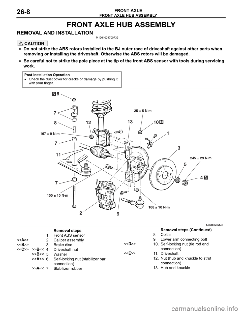
FRONT AXLE HUB ASSEMBLY
FRONT AXLE26-8
FRONT AXLE HUB ASSEMBLY
REMOVAL AND INSTALLATIONM1261001700739
CAUTION
•Do not strike the ABS rotors installed to the BJ outer race of driveshaft against other parts when
removing or installing the driveshaft. Otherwise the ABS rotors will be damaged.
•
Post-installation Operation
•Check the dust cover for cracks or damage by pushing it
with your finger.
AC209505
N
N
N
5
4
3
1
8
10
9
2
7
6
167 ± 9 N·m 25 ± 5 N·m
108 ± 10 N·m 245 ± 29 N·m
100 ± 10 N·m
AC
7 7
11 12
13
Removal steps
1. Front ABS sensor
<> 2. Caliper assembly
<> 3. Brake disc
<
>>B<<5. Washer
>>A<<6.Self-locking nut (stabilizer bar
connection)
>>A<<7.Stabilizer rubber
8.Collar
9. Lower arm connecting bolt
<
connection)
<
12.Nut (hub and knuckle to strut
connection)
13.Hub and knuckle
Be careful not to strike the pole piece at the tip of the front ABS sensor with tools during servicing
work.
Removal steps (Continued)
Page 143 of 800
FRONT AXLE HUB ASSEMBLY
FRONT AXLE26-11
INSPECTION
M1261001800242
•Check the hub for cracks and spline for wear.
•Check the knuckle for cracks.
•Check for defective bearing.
NOTE: If the meshing of the wheel bearing outer
race and the knuckle, or of the wheel bearing
inner race and the hub, is loose, replace the
bearing or damaged parts.
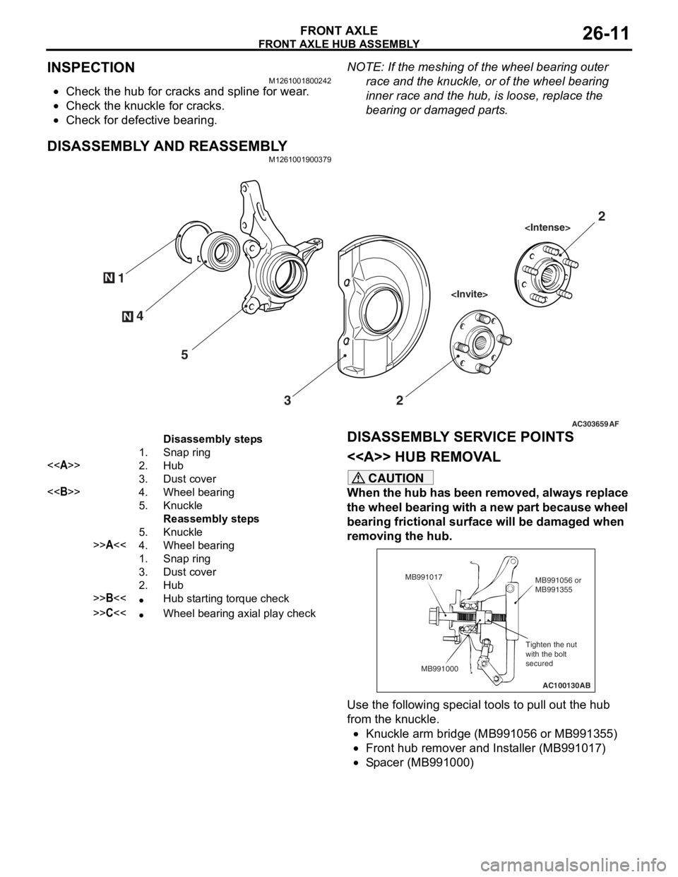
DISASSEMBLY AND REASSEMBLY
M1261001900379
AC303659
N
N4
1
5 3 2
AF
2
Disassembly steps
1.Snap ring
<>2.Hub
3.Dust cover
<>4.Wheel bearing
5.Knuckle
Reassembly steps
5.Knuckle
>>A<<4.Wheel bearing
1.Snap ring
3.Dust cover
2.Hub
>>B<<•Hub starting torque check
>>C<<•Wheel bearing axial play check
DISASSEMBL
Y SER V ICE POINTS
< > HUB REMOV A L
CAUTION
When the hub has been removed, always replace
the wheel bearing with a new part because wheel
bearing frictional surface will be damaged when
removing the hub.
AC100130
Tighten the nut
with the bolt
secured MB991056 or
MB991355
MB991017
MB991000 AB
Use the following special tools to pull out the hub
from the knuckle.
•Knuckle arm bridge (MB991056 or MB991355)
•Front hub remover and Installer (MB991017)
•Spacer (MB991000)
Page 144 of 800
FRONT AXLE HUB ASSEMBLY
FRONT AXLE26-12
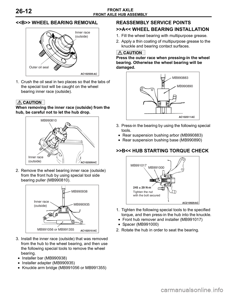
<> WHEEL BEARING REMOVAL
AC102508AC
Inner race
(outside)
Outer oil seal
1. Crush th e oil seal in two pl ace s so t hat t he t abs of
th e spe c ia l too l will be caugh t on th e wheel
be aring inne r race (out side).
CAUTION
When removing the inner race (outside) from the
hub, be careful not to let the hub drop.
AC102509
MB990810
Inner race
(outside)
AC
2. Remove the wheel bearing inner race (outside) from the front hub by using special tool side
bearing puller (MB990810).
AC102510 AC
MB990938
MB990935
MB991056 or MB991355
Inner race
(outside)
3. Install the inner race (outside) that was removed
from the hub to the wheel bearing, and then use
the following special tools to remove the wheel
bearing.
•Installer bar (MB990938)
•Installer adapter (MB990935)
•Knuckle arm bridge (MB991056 or MB991355)
REASSEMBLY SERVICE POINTS
>>A<< WHEEL BEARING INSTALLATION
1. Fill the wheel bearing with multipurpose grease.
2. Apply a thin coating of multipurpose grease to the knuckle and bearing contact surfaces.
CAUTION
Press the outer race when pressing-in the wheel
bearing. Otherwise the wheel bearing will be
damaged.
AC102511
MB990883
MB990890
AC
3. Press-in the bearing by using the following special tools.
•Rear suspension bushing arbor (MB990883)
•Rear suspension bushing base (MB990890)
>>B<< HUB STARTING TORQUE CHECK
AC210929AC
MB991000
MB991017
245 ± 29 N·m
Tighten the nut
with the bolt secured
1. Tighten the following special tools to the specified torque, and then press-in the hub into the knuckle.
•Front hub remover and installer (MB991017)
•Spacer (MB991000)
2. Rotate the hub in order to seat the bearing.
Page 145 of 800
AC100136
MB990685MB990326
AB
FRONT AXLE HUB ASSEMBL Y
FRONT AXLE26-13
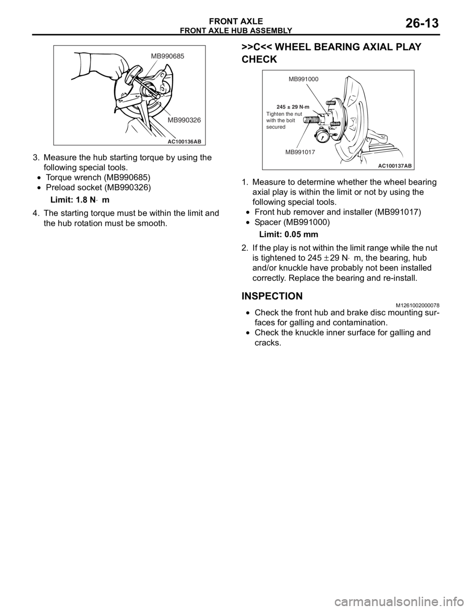
3.Measure the hub st a r ting torque b y using the
fo llowing special to ols.
•To rque wren ch (MB99068 5)
•Preload socket (MB9 90326 )
Limit: 1.8 N⋅m
4.Th e st arting torq ue must b e within the limit an d
th e hub rot a tion must be smoo th.
>>C<< WH EEL BEARING AXIAL PLA Y
CHECK
AC100137
MB991000
MB991017
245 ± 29 N·m AB
Tighten the nut
with the bolt
secured
1.
Measure to d e termine whe t her th e wheel bearing
a x ial pla y is with in the limit o r not by using t he
fo llowing special to ols.
•Front hub re mover and inst a ller (MB9910 17)
•Sp a c er (MB9910 00)
Limit: 0.05 mm
2. If the play is not wit h in the limit rang e while the nut
is tighten ed to 2 45
± 29 N⋅m, the bearing, hu b
a
nd/or knuckle
have
proba
bly not be en in st alled
correctly
. Replace
the be
aring and re -inst a ll.
INSPECTION
M12610020 0007 8
•Check the fro n t hu b and brake disc mo untin g sur-
faces for gallin g and cont amination.
•Check the knu c kle in ner surface for ga lling an d
crac
ks .