check MITSUBISHI LANCER IX 2006 Service Manual
[x] Cancel search | Manufacturer: MITSUBISHI, Model Year: 2006, Model line: LANCER IX, Model: MITSUBISHI LANCER IX 2006Pages: 800, PDF Size: 45.03 MB
Page 381 of 800
DOOR MIRROR
EXTERIOR51-49
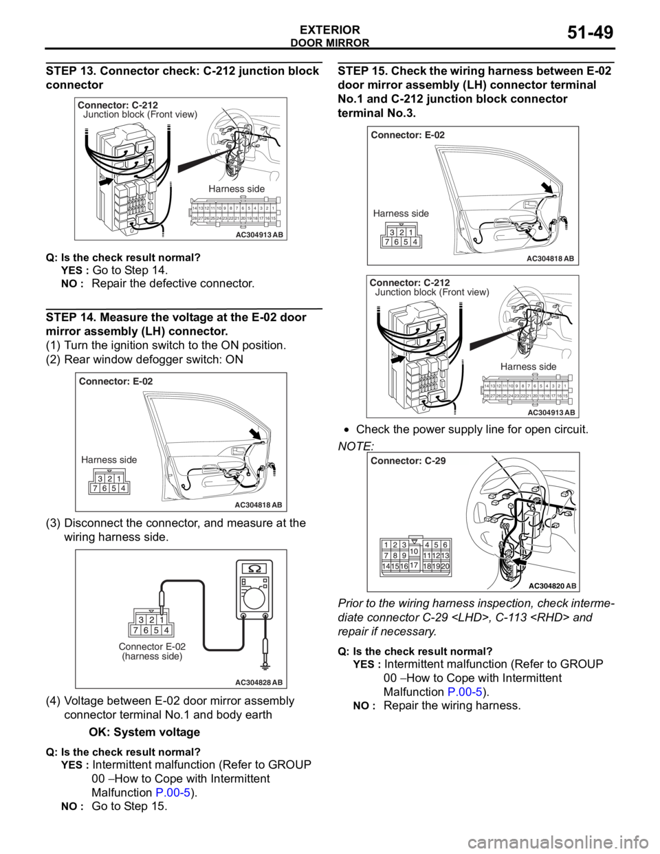
STEP 13. Connector check: C-212 junction block
connector
AC304913
21716151718
201912345
623 222425282627981011141213
Connector: C-212
Harness side
AB
Junction block (Front view)
Q : Is the check result normal?
YES : Go to S t ep 14 .
NO : Repa ir the defective connector .
STEP 14 . Me asure the volt age at the E-02 door
mirror a
ssembl y (LH) conne ctor .
(1)T urn t he ig nition switch to the ON positio n.
(2)R ear win dow defo gger switch : ON
AC304818
Connector: E-02
Harness side
AB
(3) D isconn ect t he co nnector , an d me asure at the
wiring harn e ss side.
AC304828
Connector E-02(harness side)
AB
(4) V olt a g e between E-02 doo r mirror assembly
co nnector termina l No.1 a nd bod y ea rth
OK: System vo lt age
Q: Is the check result normal?
YES : Intermittent ma lfun ctio n (Refer to GROUP
00
− Ho w t o Cope wit h Intermitte nt
Malfunction
P.00-5).
NO : Go to S t ep 15 .
STEP 1 5 . Chec k the wiring ha rnes s betwe en E-02
door mirror assem
bly (LH) con nector termina l
No.
1 and C-21 2 junctio n block connec tor
terminal No.3
.
AC304818
Connector: E-02
Harness side
AB
AC304913
21 716151718
201912345
623 222425282627981011141213
Connector: C-212
Harness side
AB
Junction block (Front view)
•Check th e power supply line fo r open circuit.
NOTE:
AC304820
Connector: C-29
AB
Prior to the wiring harness insp ection, check interme-
diate connector C-29
rep
a ir if necessary .
Q:Is t h e che c k r esu lt n o rmal?
YES : Intermittent malfun ctio n (Refer to GROUP
00
− Ho w to Cope wit h Intermitte nt
Ma
lfunction
P.00-5).
NO : Repa ir th e wirin g harne ss.
Page 383 of 800

DOOR MIRROR
EXTERIOR51-51
Push the top of the mirror with your hand to tilt it and
attach the protective tape as shown in the illustration.
Then insert a flat-tipped screwdriver in between the
notch at the rear of the mirror and the pivot plate, and
disengage the bottom of the mirror.
INSTALLATION SERVICE POINT
>>A<< MIRROR INSTALLATION
AC00044200007258
Mirror
Flat-tipped
screwdriver
Section A – A
Pivot plate
A
A A
A
AB
W h il e su pp ort i ng t he clip po siti on on th e u nde rsi de of
the pivot p
l ate with a flat -tipped screwdr i ver , press
t
he clip at th e front of the mirror t o engage t he botto m
of the mirro
r .
INSPECTION
M151 1 0065 0028 6
ELECTRIC REMOTE CONTROL MIRROR
OPERA
T ION CHECK < V EHICLES WITH
-
OUT HEAT ED DOOR MIRROR>
3
2
1
AC005969
Ch eck that th e mirror moves as describe d in the
t
a b l e when each terminal is conn ecte d to the batte ry .
Battery connectionDirection
operation
•Connect terminal 1 to the negative
battery terminal.
•Connect terminal 3 to the positive
battery terminal.
Mirror
glass
should face
upward
•Connect terminal 3 to the negative
battery terminal.
•Connect terminal 1 to the positive
battery terminal.
Mirror
glass
should face
downward
•Connect terminal 1 to the negative
battery terminal.
•Connect terminal 2 to the positive
battery terminal.
Mirror
glass
should face
to the right
•Connect terminal 2 to the negative
battery terminal.
•Connect terminal 1 to the positive
battery terminal.
Mirror
glass
should face
to the left
Page 384 of 800
DOOR MIRROR
EXTERIOR51-52
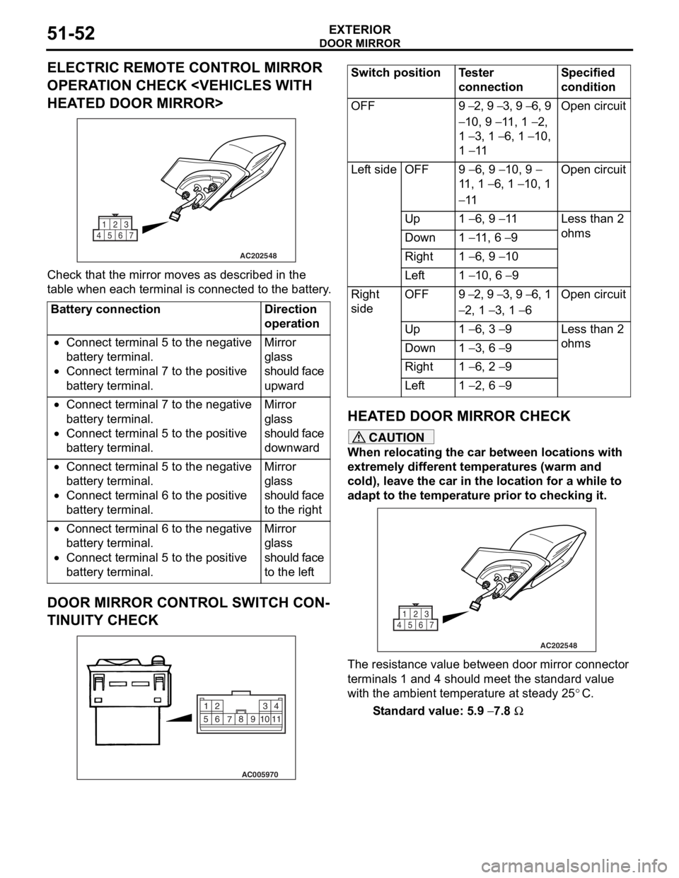
ELECTRIC REMOTE CONTROL MIRROR
OPERATION CHECK
AC202548
1
4567 23
Che
c k that th e mirror moves as describe d in the
t
a b l e when each terminal is conn ecte d to the batter y .
Battery connectionDirection
operation
•Connect terminal 5 to the negative
battery terminal.
•Connect terminal 7 to the positive
battery terminal.
Mirror
glass
should face
upward
•Connect terminal 7 to the negative
battery terminal.
•Connect terminal 5 to the positive
battery terminal.
Mirror
glass
should face
downward
•Connect terminal 5 to the negative
battery terminal.
•Connect terminal 6 to the positive
battery terminal.
Mirror
glass
should face
to the right
•Connect terminal 6 to the negative
battery terminal.
•Connect terminal 5 to the positive
battery terminal.
Mirror
glass
should face
to the left
DOOR MIRROR CONTROL SWITCH CON-
TINUITY CHECK
AC005970
2
14
3
510 9
8
7
6
11
Switch positionTester
connectionSpecified
condition
OFF9 − 2, 9 − 3, 9 − 6, 9
− 10, 9 − 11, 1 − 2,
1
− 3, 1 − 6, 1 − 10,
1
− 11
Open circuit
Left sideOFF9 − 6, 9 − 10, 9 −
11 , 1
− 6, 1 − 10, 1
− 11
Open circuit
Up1 − 6, 9 − 11Less than 2
ohms
Down1 − 11, 6 − 9
Right1 − 6, 9 − 10
Left1 − 10, 6 − 9
Right
sideOFF9 − 2, 9 − 3, 9 − 6, 1
− 2, 1 − 3, 1 − 6
Open circuit
Up1 − 6, 3 − 9Less than 2
ohms
Down1 − 3, 6 − 9
Right1 − 6, 2 − 9
Left1 − 2, 6 − 9
HEA T ED DOOR MIRROR CHECK
CAUTION
When relocating the car between locations with
extremely different temperatures (warm and
cold), leave the car in the location for a while to
adapt to the temperature prior to checking it.
AC202548
1
4567 23
The resistance value between door mirror connector
terminals 1 and 4 should meet the standard value
with the ambient temperature at steady 25
°C.
Standard value: 5.9 − 7.8 Ω
Page 484 of 800

CENTRALIZED JUNCTION
CIRCUIT DIAGRAMS90-20
PASSENGER COMPARTMENT
AC207745
(Connected directly to battery positive terminal)
Front of vehicle26
AF
No.Power supply circuitNameRated
capacity (A)Housing
colourLoad circuit
1Ignition switch (IG1)Fuse10RedCapacitor and ignition coil
27.5BrownABS warning lamp, brake warning
lamp, charging warning lamp, check
engine warning lamp, column switch,
combination meter, ETACS-ECU, low
fuel warning lamp, oil pressure
warning lamp, SRS air bag warning
lamp, SRS-ECU and vehicle speed
sensor
37.5BrownA/T control relay, combination meter,
engine-A/T-ECU, ETACS-ECU, input
shaft speed sensor, output shaft
speed sensor, rear combination lamp
and SRS-ECU
4−−−
5Ignition switch (IG2)7.5BrownA/C compressor relay, A/C-ECU,
blower relay, rear window defogger
relay, front-ECU, heated seat relay,
heater control unit and outside/inside
air selection damper control motor
6Rear window
defogger relay7.5BrownRemote controlled mirror
7Ignition switch (ACC)20YellowFront-ECU and windshield wiper
motor
8Ignition switch (IG1)7.5BrownEngine-A/T-ECU, engine-ECU, fuel
pump relay (1) and fuel pump relay (2)
9Ignition switch (ACC)15BlueCigarette lighter
10−−−
117.5BrownAccessory socket relay and Remote
controlled mirror
12Ignition switch (IG2)7.5BrownABS-ECU
13Ignition switch (ACC)−−−
1415BlueETACS-ECU and rear wiper motor