ESP MITSUBISHI LANCER IX 2006 Service Manual
[x] Cancel search | Manufacturer: MITSUBISHI, Model Year: 2006, Model line: LANCER IX, Model: MITSUBISHI LANCER IX 2006Pages: 800, PDF Size: 45.03 MB
Page 8 of 800

GENERAL INFORMATION
ENGINE LUBRICATION12-2
GENERAL INFORMATION
M1121000100357
The lubrication method is a fully force-fed, full-flow fil-
tration type. The engine oil pump is a trochoid type
which is driven by the crankshaft <4G1>.The engine
oil pump is a gear type which is driven by the crank
-
shaft via the balancer timing belt <4G6>.
ENGINE OILS
Health Warning
Prolonged and repeated contact with mineral oil will
result in the removal of natural fats from the skin,
leading to dryness, irritation and dermatitis. In addi
-
tion, used engine oil contains potentially harmful con-
taminants which may cause skin cancer. Adequate
means of skin protection and washing facilities must
be provided.
Recommended Precautions
The most effective precaution is to adapt working
practices which prevent, as far as practicable, the
risk of skin contact with mineral oils, for example by
using enclosed systems for handling used engine oil
and by degreasing components, where practicable,
before handling them. Other precautions:
•Avoid prolonged and repeated contact with oils,
particularly used engine oils.
•Wear protective clothing, including impervious
gloves where practicable.
•Avoid contaminating clothes, particularly under-
pants, with oil.
•Do not put oily rags in pockets, the use of overalls
without pockets will avoid this.
•Do not wear heavily soiled clothing and
oil-impregnated foot-wear. Overalls must be
cleaned regularly and kept separate from per
-
sonal clothing.
•Where there is a risk of eye contact, eye protec-
tion should be worn, for example, chemical gog-
gles or face shields; in addition an eye wash
facility should be provided.
•Obtain first aid treatment immediately for open
cuts and wounds.
•Wash regularly with soap and water to ensure all
oil is removed, especially before meals (skin
cleansers and nail brushes will help). After clean
-
ing, the application of preparations containing
lanolin to replace the natur al skin oils is advised.
•Do not use petrol, kerosine, diesel fuel, gas oil,
thinners or solvents for cleaning skin.
•Use barrier creams, applying them before each
work period, to help the removal of oil from the
skin after work.
•If skin disorders develop, obtain medical advice
without delay.
SERVICE SPECIFICATION
M1121000300232
ItemStandard value
Oil pressure kPaat idle29 or more
at 3,500 r/min294 − 686
LUBRICANT
M1121000400433
ItemSpecification
Engine oil ACEA classificationA1, A2 or A3
Engine oil API classificationSG or higher
Engine oil quantity L4G1Oil filter0.3
To t a l3.3
4G6Oil filter0.3
To t a l4.3
Page 11 of 800
ON-VEHICLE SERVICE
ENGINE LUBRICATION12-5
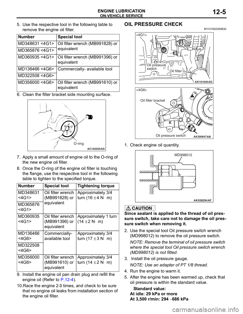
5. Use the respective tool in the following table to remove the engine oil filter.
NumberSpecial tool
MD348631 <4G1>Oil filter wrench (MB991828) or
equivalent
MD365876 <4G1>
MD360935 <4G1>Oil filter wrench (MB991396) or
equivalent
MD136466 <4G6>Commercially- available tool
MD322508 <4G6>
MD356000 <4G6>Oil filter wrench (MB991610) or
equivalent
6. Cle an the filt er bracket side mou n ting surfa c e.
AC103250AD
O-ring
7.Ap ply a small a m ou nt o f en gine o i l to th e O-rin g of
th e new eng ine oil f ilte r .
8.Once the O-ring of the engine oil filter is tou c hing
th e flange, use the resp ective tool in the following
t able to tighten to the specified tor que.
NumberSpecial toolTightening torque
MD348631
<4G1>Oil filter wrench
(MB991828) or
equivalentApproximately 3/4
turn (16
± 4 N⋅m)
MD365876
<4G1>
MD360935
<4G1>Oil filter wrench
(MB991396) or
equivalentApproximately 1 turn
(14
± 2 N⋅m)
MD136466
<4G6>Commercially-
available toolApproximately 3/4
turn (17
± 3 N⋅m)
MD322508
<4G6>
MD356000
<4G6>Oil filter wrench
(MB991610) or
equivalentApproximately 3/4
turn (14
± 2 N⋅m)
9.In st all the en gine oil p a n drain plu g and refill the
en gine oil (Re f er to
P.12-4).
10.Race the en gine 2−3 times, and che ck to be sure
th
at n
o
en
gin
e
oil leaks fr om in st allation sectio n of
th
e engine oil filter
.
OIL PRESSURE CHECK
M1 121 0023 0083 0
AK101640
<4G1>
Oil pressure
switch
Oil filter
AD
AK300647
AB
<4G6>
Oil filter bracket
Oil pressure switch
1.Check e ngin e oil quan tity .
AKX00294
MD998012
AF
CAUTION
Since sealant is applied to the thread of oil pres-
sure switch, take care not to damage the oil pres-
sure switch when removing it.
2. Use the special tool Oil pressure switch wrench
(MD998012) to remove the oil pressure switch.
NOTE: Remove the terminal of oil pressure switch
where the special tool Oil pressure switch wrench
(MD998012) is not fitted.
3. Install the oil pressure gauge.
NOTE: Use an adapter of PT 1/8 thread.
4. Run the engine to warm it.
5. After the engine has been warmed up, check that oil pressure is within the standard value.
Standard value:
At idle: 29 kPa or more
At 3,500 r/min: 294 − 686 kPa
Page 92 of 800
IGNITION SYSTEM
ENGINE ELECTRICAL16-30
IGNITION SYSTEM
GENERAL INFORMATIONM1163000100294
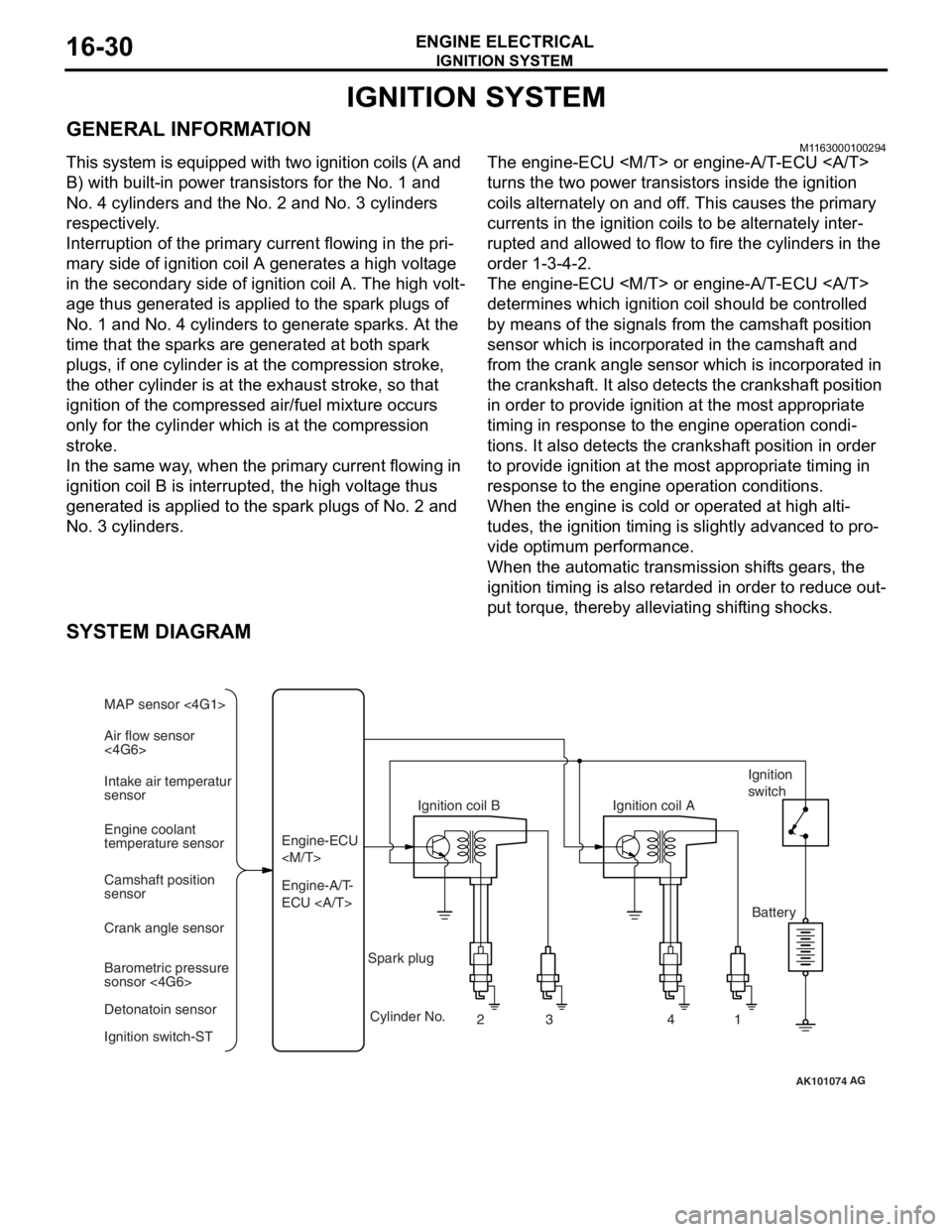
This system is equipped with two ignition coils (A and
B) with built-in power transistors for the No. 1 and
No. 4 cylinders and the No. 2 and No. 3 cylinders
respectively.
Interruption of the primary current flowing in the pri-
mary side of ignition coil A generates a high voltage
in the secondary side of ignition coil A. The high volt
-
age thus generated is applied to the spark plugs of
No. 1 and No. 4 cylinders to generate sparks. At the
time that the sparks are generated at both spark
plugs, if one cylinder is at the compression stroke,
the other cylinder is at the exhaust stroke, so that
ignition of the compressed air/fuel mixture occurs
only for the cylinder which is at the compression
stroke.
In the same way, when the primary current flowing in
ignition coil B is interrupted, the high voltage thus
generated is applied to the spark plugs of No. 2 and
No. 3 cylinders.
The engine-ECU
turns the two power transistors inside the ignition
coils alternately on and off. This causes the primary
currents in the ignition coils to be alternately inter
-
rupted and allowed to flow to fire the cylinders in the
order 1-3-4-2.
The engine-ECU
determines which ignition coil should be controlled
by means of the signals from the camshaft position
sensor which is incorporated in the camshaft and
from the crank angle sensor which is incorporated in
the crankshaft. It also detects the crankshaft position
in order to provide ignition at the most appropriate
timing in response to the engine operation condi
-
tions. It also detects the crankshaft position in order
to provide ignition at the most appropriate timing in
response to the engine operation conditions.
When the engine is cold or operated at high alti-
tudes, the ignition timing is slightly advanced to pro-
vide optimum performance.
When the automatic transmission shifts gears, the
ignition timing is also retarded in order to reduce out
-
put torque, thereby alleviating shifting shocks.
SYSTEM DIAGRAM
AK101074
Air flow sensor
<4G6> MAP sensor <4G1>
Intake air temperatur
sensor
Engine coolant
temperature sensor
Camshaft position
sensor
Crank angle sensor
Barometric pressure
sonsor <4G6>
Detonatoin sensor
Ignition switch-ST Engine-A/T-
ECU Engine-ECU
Ignition coil B
Cylinder No. 23 4
AG
1
Spark plug Ignition coil A
Ignition
switch
Battery
Page 110 of 800

EMISSION CONTROL
ENGINE AND EMISSION CONTROL17-4
INSTALLATION SERVICE POINT
>>A<< ACCEL PEDAL PAD INSTALLA-
TION
CAUTION
To prevent damages to the accelerator pedal pad,
warm the thumb area of the accelerator pedal
pad with a dryer, etc. prior to assembling it.
NOTE: If it is difficult to assemble, apply soapy water
to the thumb area to enhance the assembling proc
-
ess.
EMISSION CONTROL
GENERAL INFORMATION
M1173000100370
The emission control system consists of the following
subsystems:
•Crankcase emission control system
•Evaporative emission control system
•
ItemsNameSpecification
Crankcase emission control
systemPositive crankcase ventilation
(PCV) valveVariable flow type
(Purpose: HC reduction)
Evaporative emission control
systemCanister
Purge control solenoid valve
Equipped
Duty cycle type solenoid valve
(Purpose: HC reduction)
Exhaust emission control systemAir-fuel ratio control device - MPI
systemOxygen sensor feedback type
(Purpose: CO, HC, NOx reduction)
Exhaust gas recirculation system
•EGR valve
•EGR control solenoid valve
Equipped
Single type
Duty cycle type solenoid valve
(Purpose: NOx reduction)
Catalytic converterMonolith type
(Purpose: CO, HC, NOx reduction)
Exhaust emission control system
EMISSION CONTROL DEVICE
REFERENCE TABLE
M1173006600135
Related partsCrankcase
emission
control
systemEvaporative
emission
control
systemAir/fuel ratio
control
systemCatalytic
converterExhaust gas
recirculation
system
PCV valve×
Purge control solenoid valve×
MPI system component××
Catalytic converter×
EGR valve×
EGR control solenoid valve×
7.Accelerator control equip bushing
8.Accelerator pedal arm return spring
9.Accelerator pedal arm stopper
10.Accelerator pedal arm bracket
11 .Accelerator pedal arm
>>A<<12.Accelerator pedal pad
13.Accelerator pedal arm stopper
Accelerator pedal assembly
removal steps (Continued)
Page 152 of 800
DRIVESHAFT ASSEMBLY
FRONT AXLE26-20
REASSEMBLY SERVICE POINTS
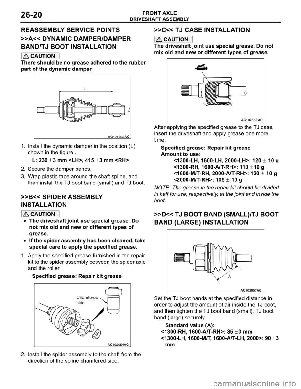
>>A<< DYNAMIC DAMPER/DAMPER
BAND/TJ BOOT INSTALLATION
CAUTION
There should be no grease adhered to the rubber
part of the dynamic damper.
AC101695AC
L
1. Install the dynamic damper in the position (L)
shown in the figure .
L: 230 ± 3 mm
2. Secure the damper bands.
3. Wrap plastic tape around the shaft spline, and then install the TJ boot band (small) and TJ boot.
>>B<< SPIDER ASSEMBLY
INSTALLATION
CAUTION
•The driveshaft joint use special grease. Do
not mix old and new or different types of
grease.
•If the spider assembly has been cleaned, take
special care to apply the specified grease.
1. Apply the specified grease furnished in the repair kit to the spider assembly between the spider axle
and the roller.
Specified grease: Repair kit grease
AC102654AC
Chamfered
side
2. Install the spider assembly to the shaft from the direction of the spline chamfered side.
>>C<< TJ CASE INSTALLATION
CAUTION
The driveshaft joint use special grease. Do not
mix old and new or different types of grease.
AC102656AC
After applying the specified grease to the TJ case,
insert the driveshaft and apply grease one more
time.
Specified grease: Repair kit grease
Amount to use:
<1300-LH, 1600-LH, 2000-LH>: 120 ± 10 g
<1300-RH, 1600-A/T-RH>: 110 ± 10 g
<1600-M/T-RH, 2000-A/T-RH>: 120 ± 10 g
<2000-M/T-RH>: 105 ± 10 g
NOTE: The grease in the repair kit should be divided
in half for use, respectively, at the joint and inside the
boot.
>>D<< TJ BOOT BAND (SMALL)/TJ BOOT
BAND (LARGE) INSTALLATION
AC102657
A
AC
Set the TJ boot bands at the specified distance in
order to adjust the amount of air inside the TJ boot,
and then tighten the TJ boot band (small), TJ boot
band (large) securely.
Standard value (A):
<1300-RH, 1600-A/T-RH>: 85 ± 3 mm
<1300-LH, 1600-M/T, 1600-A/T-LH, 2000>: 90 ± 3
mm
Page 183 of 800
33-1
GROUP 33
FRONT
SUSPENSION
CONTENTS
GENERAL INFORMATIO N . . . . . . . .33-2
SERVICE SPECIFICATIONS . . . . . . .33-3
LUBRICANT . . . . . . . . . . . . . . . . . . . .33-3
SPECIAL TOOLS . . . . . . . . . . . . . . . .33-4
ON-VEHICLE SERVICE . . . . . . . . . . .33-6
FRONT WHEEL ALIGNMENT CHECK AND
ADJUSTMENT . . . . . . . . . . . . . . . . . . . . . . 33-6
LOWER ARM BALL JOINT AXIAL PLAY
CHECK . . . . . . . . . . . . . . . . . . . . . . . . . . . . 33-7
LOWER ARM BALL JOINT COVER
CHECK . . . . . . . . . . . . . . . . . . . . . . . . . . . . 33-7
STRUT ASSEMBLY . . . . . . . . . . . . . .33-7
REMOVAL AND INSTALLATION . . . . . . . . 33-7
INSPECTION. . . . . . . . . . . . . . . . . . . . . . . . 33-7
DISASSEMBLY AND REASSEMBLY . . . . . 33-8
INSPECTION. . . . . . . . . . . . . . . . . . . . . . . . 33-10
LOWER ARM . . . . . . . . . . . . . . . . . . .33-11
REMOVAL AND INSTALLATION . . . . . . . . 33-11
INSPECTION. . . . . . . . . . . . . . . . . . . . . . . . 33-12
LOWER ARM BALL JOINT COVER
REPLACEMENT . . . . . . . . . . . . . . . . . . . . . 33-12
LOWER ARM BUSHING (REAR)
REPLACEMENT . . . . . . . . . . . . . . . . . . . . . 33-13
STABILIZER BAR. . . . . . . . . . . . . . . .33-14
REMOVAL AND INSTALLATION . . . . . . . . 33-14
INSPECTION. . . . . . . . . . . . . . . . . . . . . . . . 33-16
WARNINGS REGARDING SERVICING OF SUPPLEMENTAL RESTRAINT SYSTEM (SRS) EQUIPPED VEHICLES
WARNING
•Improper service or maintenance of any component of the SRS, or any SRS-related component, can lead to
personal injury or death to service personnel (from inad vertent firing of the air bag) or to the driver and
paassenger (from rendering the SRS inoperative).
•Service or maintenance of any SRS component or SRS-related component must be performed only at an
authorized MITSUBISHI dealer.
•MITSUBISHI dealer personnel must thoroughly review this manual, and especially its GROUP 52B - Supplemental
Restraint System (SRS) before beginning any service or maintenance of any component of the SRS or any
SRS-related component.
NOTE
The SRS includes the following components: SRS air bag control unit, SRS warning light, front impact sensors, air bag module,
clock spring, and interconnecting wiring. Other SRS-related components (that may have to be removed/installed in connection
with SRS service or maintenance) are indicated in the table of contents by an asterisk (*).
Page 229 of 800
PARKING BRAKE LINING AND DRUM
PARKING BRAKES36-9
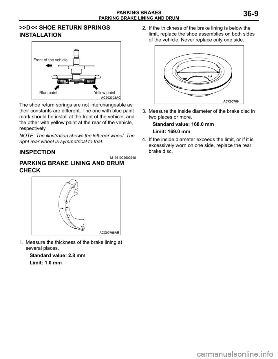
>>D<< SHOE RETURN SPRINGS
INSTALLATION
AC202302AC
Front of the vehicleBlue paint Yellow paint
The shoe ret u rn sp rings are n o t in tercha ngeab le as
their const
a nt s are d i f f e r ent. Th e one with blue p a in t
mark
should be inst a ll at t he fron t o f th e vehicle, and
the oth
e r with yellow p a int a t the re ar of th e ve hicle,
respectively
.
NOTE: The ill ustratio n sh ows th e lef t rear whee l. T he
right re
ar wheel is symme trical to that.
INSPECTION
M13610026 0024 8
PARKING BRAKE LI NING AND DRUM
CHECK
ACX00708AB
1.
Measure the thickne ss of the b r ake lining at
seve ral place s .
St andard va lue: 2.8 mm
Limit: 1.0 mm
2.If the thickness of t he brake linin g is belo w the
limit, rep l ace the shoe a s semblies on bo th sides
o f the vehicle. Ne ver re place only on e side.
ACX00709
3.Measure the inside d i ameter of the bra k e d i sc in
two p l aces o r more .
St andard va lue: 16 8.0 mm
Limit: 169.0 mm
4.If the inside diamete r exceeds the limit, or if it is
e xce ssively worn on one side, rep l ace the re ar
b r ake d i sc.
Page 231 of 800
37-1
GROUP 37
POWER STEERING
CONTENTS
GENERAL INFORMATION . . . . . . . .37-3
SERVICE SPECIFICATIONS . . . . . . .37-6
LUBRICANTS . . . . . . . . . . . . . . . . . .37-7
SEALANTS . . . . . . . . . . . . . . . . . . . .37-7
SPECIAL TOOLS . . . . . . . . . . . . . . . .37-8
ON-VEHICLE SERVICE . . . . . . . . . . .37-11
STEERING WHEEL FREE PLAY CHECK . 37-11
STEERING ANGLE CHECK . . . . . . . . . . . . 37-11
TIE ROD END BALL JOINT TURNING
TORQUE CHECK . . . . . . . . . . . . . . . . . . . . 37-12
STATIONARY STEERING EFFORT
CHECK . . . . . . . . . . . . . . . . . . . . . . . . . . . . 37-12
STEERING WHEEL RETURN TO
CENTRE CHECK . . . . . . . . . . . . . . . . . . . . 37-13
DRIVE BELT TENSION CHECK. . . . . . . . . 37-13
FLUID LEVEL CHECK . . . . . . . . . . . . . . . . 37-13
FLUID REPLACEMENT . . . . . . . . . . . . . . . 37-13
POWER STEERING SYSTEM AIR
BLEEDING . . . . . . . . . . . . . . . . . . . . . . . . . 37-14
OIL PUMP PRESSURE TEST . . . . . . . . . . 37-14
POWER STEERING PRESSURE
SWITCH CHECK . . . . . . . . . . . . . . . . . . . . . 37-15
TIE ROD END BALL JOINT DUST
COVER CHECK . . . . . . . . . . . . . . . . . . . . . 37-15
STEERING COLUMN SHAFT ASSEMBLY
SHOCK ABSORBING MECHANISM
CHECK . . . . . . . . . . . . . . . . . . . . . . . . . . . . 37-15
STEERING WHEEL . . . . . . . . . . . . . .37-17
REMOVAL AND INSTALLATION
REMOVAL AND INSTALLATION
Continued on next page
WARNINGS REGARDING SERVICING OF SUPPLEMENTAL RESTRAINT SYSTEM (SRS) EQUIPPED VEHICLES
WARNING
•Improper service or maintenance of any component of the SRS, or any SRS-related component, can lead to
personal injury or death to service personnel (from inad vertent firing of the air bag) or to the driver and
paassenger (from renderin g the SRS inoperative).
•Service or maintenance of any SRS component or SRS-related component must be performed only at an
authorized MITSUBISHI dealer.
•MITSUBISHI dealer personnel must thoroughly review th is manual, and especially its GROUP 52B - Supplemental
Restraint System (SRS) before begi nning any service or maintenance of any component of the SRS or any
SRS-related component.
NOTE
The SRS includes the following components: SRS air bag control unit, SRS warning light, front impact sensors, air bag module,
clock spring, and interconnecting wiring. Other SRS-related components (that may have to be removed/installed in connection
with SRS service or maintenance) are indicated in the table of contents by an asterisk (*).
Page 233 of 800

GENERAL INFORMATION
POWER STEERING37-3
GENERAL INFORMATION
M1372000100661
Power steering has been adopted in all vehicles to
make the steering system easier to handle.
FEATURES
•A 4-spoke steering wheel is used.
•MOMO leather-wrapped 3-spoke steering wheel
is used.
•A steering column has a shock absorbing mecha-
nism and a tilt steering mechanism.
•Integral-type rack and pinion gear with high rigid-
ity and excellent response is used.
•A vane type pump with a fluid flow rate control
system which change steering effort according to
the engine speed is used.
•The separate plastic resin oil reservoir is used to
reduce weight and to make the fluid level check
-
ing easier.
SPECIFICATIONS
ItemInviteIntense
Steering
wheelTy p e4-spoke typeMOMO leather-wrapped
3-spoke type
Outside diameter mm380365
Maximum number of turns3.193.08
Steering
columnColumn mechanismShock absorbing mechanism and Tilt steering mechanism
Power steering typeIntegral type
Oil pumpTy p eVane pump
Basic discharge amount cm3/rev.7.2 <1300, 1600>
8.1 <2000>
7.2 <1300, 1600>
8.1 <2000>
Relief pressure MPa8.88.8
Reservoir typeSeparate type (plastic)
Pressure switchEquipped
Steering
gearTy p eRack and pinion
Stroke ratio (Rack stroke/Steering
wheel maximum turning radius)45.7445.74
Rack stroke mm146141
Page 243 of 800
ON-VEHICLE SERVICE
POWER STEERING37-13
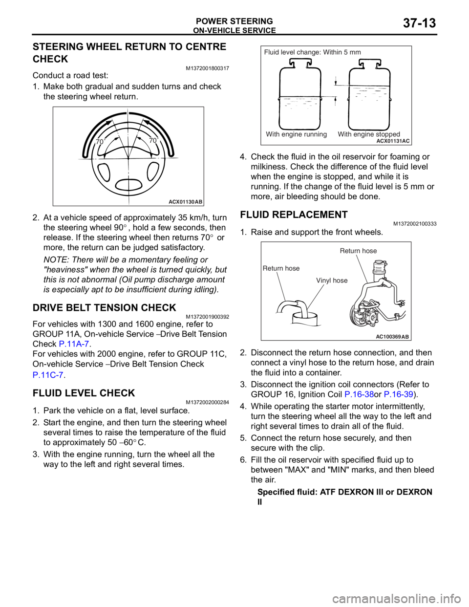
STEERING WHEEL RETURN TO CENTRE
CHECK
M1372001800317
Conduct a road test:
1. Make both gradual and sudden turns and check the steering wheel return.
ACX01130 AB
70˚ 70˚
2.
At a vehicle sp eed of a pproxima t ely 35 km/h, turn
th e ste e ring wh eel 9 0
°, ho ld a few se cond s, the n
release. If th
e ste
e
ring
wh eel t hen ret u rns 7 0
° or
more, th
e return
can
be ju
dged satisfactory
.
NOTE: There will be a mome nt a r y fee lin g or
"he
a
viness" when t he wheel is turned quickly , but
th
is is n o t abno rmal (Oil pu mp discharge amou nt
is especially a p t to b e insufficie n t during id lin g).
DRIVE BELT TENSION CHECK
M13720019 0039 2
For vehicles with 13 00 and 1600 engin e , refer to
GROUP 1
1 A, On-vehicle Service
− Drive Belt T ension
Che
c
k
P.11A-7.
For veh i cles wit h 2000 e ngin e , refer to GROUP 1 1 C,
On-vehicle Se
rvice
− Drive Belt Te nsion Check
P.1 1 C - 7.
FLUID LEVEL CHECK
M13720020 0028 4
1.Park the vehicle on a f l at, leve l su rface .
2.S t art the engine, and t hen tu rn the ste e ring wheel
seve ral times to raise the temperat ure of th e flu i d
to approximately 50
− 60°C.
3.With the engine run n ing, turn the wheel all the
way to the lef t an d righ t several times.
ACX01131With engine running With engine stoppedAC
Fluid level change: Within 5 mm
4.Check t he flu i d in the oil r e servoir f o r foaming or
milkine s s. Check the d i f f e r ence of the fluid le vel
when the e ngine is stop ped, an d while it is
ru nning . If the chan ge of th e fluid le vel is 5 mm or
more, a i r bleedin g sh ould be don e.
FLUID REPLACEMENT
M13720021 0033 3
1.Raise a nd su pport t he fron t wheels.
AC100369AB
Return hoseReturn hose
Vinyl hose
2. Disco nnect the re turn hose connection , and then
conne ct a vinyl hose to the re turn h o se, and drain
th e flu i d into a cont ain e r .
3.Disco nnect the ignition coil con necto rs (Refe r to
GROUP 16, Ignition Coil
P.16-38or P.16-39).
4.Wh ile operat ing th e st arter moto r inter m itt ently ,
tu rn the steering whee l all the wa y to t he le f t a nd
right seve ral times to dra i n all of the fluid.
5.Conn ect the retu rn hose se curely , and then
secu re with t he clip.
6.Fill the oil reservo i r with specified fluid u p to
b e tween "MAX" and "MIN" marks, and then bleed
th e air .
Specified fluid: A TF DEXRON III or DEXRON
II