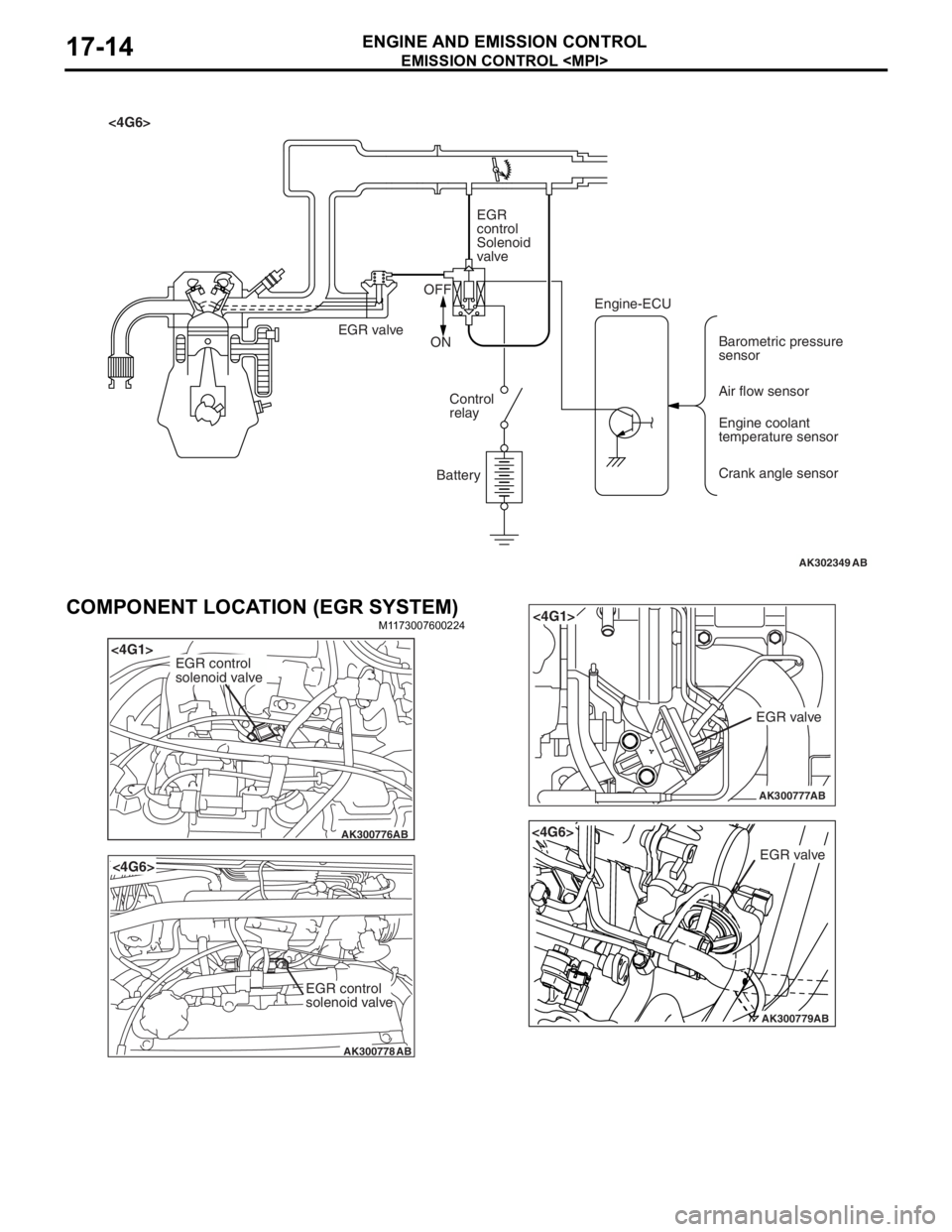
AK302349AB
<4G6>EGR
control
Solenoid
valve
EGR valve OFF
ON
Control
relay
Battery Engine-ECU
Barometric pressure
sensor
Air flow sensor
Engine coolant
temperature sensor
Crank angle sensor
EMISSION CONTROL
ENGINE AND E M ISSION CON T ROL17-14
COMPONENT LOCATION (EGR SYSTEM)
M1173 0076 0022 4
AK300776
<4G1>
AB
EGR control
solenoid valve
AK300778
<4G6>
AB
EGR control
solenoid valve
AK300777
<4G1>
AB
EGR valve
AK300779AB
<4G6>
EGR valve
DOOR MIRROR
EXTERIOR51-52
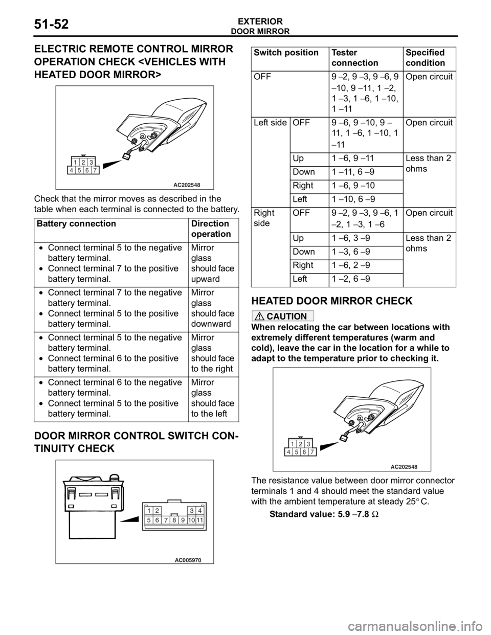
ELECTRIC REMOTE CONTROL MIRROR
OPERATION CHECK
HEATED DOOR MIRROR>
AC202548
1
4567 23
Che
c k that th e mirror moves as describe d in the
t
a b l e when each terminal is conn ecte d to the batter y .
Battery connectionDirection
operation
•Connect terminal 5 to the negative
battery terminal.
•Connect terminal 7 to the positive
battery terminal.
Mirror
glass
should face
upward
•Connect terminal 7 to the negative
battery terminal.
•Connect terminal 5 to the positive
battery terminal.
Mirror
glass
should face
downward
•Connect terminal 5 to the negative
battery terminal.
•Connect terminal 6 to the positive
battery terminal.
Mirror
glass
should face
to the right
•Connect terminal 6 to the negative
battery terminal.
•Connect terminal 5 to the positive
battery terminal.
Mirror
glass
should face
to the left
DOOR MIRROR CONTROL SWITCH CON-
TINUITY CHECK
AC005970
2
14
3
510 9
8
7
6
11
Switch positionTester
connectionSpecified
condition
OFF9 − 2, 9 − 3, 9 − 6, 9
− 10, 9 − 11, 1 − 2,
1
− 3, 1 − 6, 1 − 10,
1
− 11
Open circuit
Left sideOFF9 − 6, 9 − 10, 9 −
11 , 1
− 6, 1 − 10, 1
− 11
Open circuit
Up1 − 6, 9 − 11Less than 2
ohms
Down1 − 11, 6 − 9
Right1 − 6, 9 − 10
Left1 − 10, 6 − 9
Right
sideOFF9 − 2, 9 − 3, 9 − 6, 1
− 2, 1 − 3, 1 − 6
Open circuit
Up1 − 6, 3 − 9Less than 2
ohms
Down1 − 3, 6 − 9
Right1 − 6, 2 − 9
Left1 − 2, 6 − 9
HEA T ED DOOR MIRROR CHECK
CAUTION
When relocating the car between locations with
extremely different temperatures (warm and
cold), leave the car in the location for a while to
adapt to the temperature prior to checking it.
AC202548
1
4567 23
The resistance value between door mirror connector
terminals 1 and 4 should meet the standard value
with the ambient temperature at steady 25
°C.
Standard value: 5.9 − 7.8 Ω
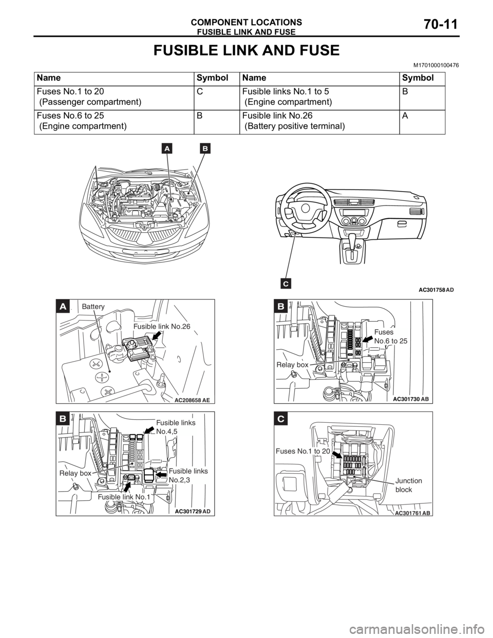
FUSIBLE LINK AND FUSE
COMPONENT LOCATIONS70-11
FUSIBLE LINK AND FUSE
M1701000100476
NameSymbolNameSymbol
Fuses No.1 to 20
(Passenger compartment)
CFusible links No.1 to 5
(Engine compartment)
B
Fuses No.6 to 25
(Engine compartment)
BFusible link No.26
(Battery positive terminal)
A
AC301758AD
AB
C
AC208658AE
A
Fusible link No.26
Battery
AC301729AD
B
Fusible link No.1
Relay box
Fusible links
No.4,5
Fusible links
No.2,3
AC301730
B
AB
Fuses
No.6 to 25
Relay box
AC301761
C
AB
Fuses No.1 to 20Junction
block


