Etacs MITSUBISHI LANCER IX 2006 Service Manual
[x] Cancel search | Manufacturer: MITSUBISHI, Model Year: 2006, Model line: LANCER IX, Model: MITSUBISHI LANCER IX 2006Pages: 800, PDF Size: 45.03 MB
Page 325 of 800
KEYLESS ENTRY SYSTEM
BODY42-53
TROUBLESHOOTING
M1428000700287
The keyless entry system is controlled by the Smart
Wiring System (SWS). For troubleshooting, refer to
GROUP 54B, Troubleshooting
P.54B-15 or GROUP
54C, Troubleshooting P.54C-4.
ON-VEHICLE SERVICE
KEYLESS ENTR Y SYSTEM CHECKM1428001400096
Check the system as described below. If the system
does not work, carry out troubleshooting. Refer to
GROUP 54B, Troubleshooting
P.54B-15, refer to
GROUP 54C, Troubleshooting P.54C-4.
•Operate the transmitter to check that the doors
and tailgate can be locked and unlocked.
•Operate the transmitter to check that the answer-
back function works in response to door and tail-
gate
NOTE: The adjustment function allows you to
change the answerback setting as follows. Prior
to that check, confirm which setting is activated.
.
•The hazard warning lamps flash twice when
locked and once when unlocked. The room
lamp flashes twice when locked and illumi
-
nates for 15 seconds when unlocked.
•The hazard warning lamps do not flash when
locked and flash once when unlocked. The
room lamp flashes twice when locked and illu
-
minates for 15 seconds when unlocked.
•The hazard warning lamps flash twice when
locked and do not flash when unlocked. The
room lamp flashes twice when locked and illu
-
minates for 15 seconds when unlocked.
•The hazard warning lamps do not flash when
both locked and unlocked. The room lamp
flashes twice when locked and illuminates for
15 seconds when unlocked.
KEYLESS ENTRY SYS TEM TIMER LOCK
FUNCTION INSPECTION
M1428004000138
Push the transmitter unlock button and check to see
that the doors and tailgate
seconds. If it doesn't, then execute troubleshooting
remedies. Refer to GROUP 54B, Troubleshooting
P.54B-15, refer to GROUP 54C, Troubleshooting
P.54C-4.
ENABLING/DISABLING THE
ANSWERBACK FUNCTION
M1428003200214
If the keyless entry system locks or unlocks the
doors, the room lamp flashes or illuminates, the haz
-
ard warning lamp flashes (hazard answerback func-
tion). The hazard answerback function can be
enabled or disabled according to the following proce
-
dure:
ENABLING/DISABLING THE HAZARD
ANSWERBACK FUNCTION
The hazard answerback function can be enabled or
disabled by one of the two following procedures.
1. Enter the hazard answerback customize mode by performing one of the following steps. If the
ETACS-ECU enters the customize mode, its
buzzer will sound once.
(1) Turn the ignition switch to “LOCK”(OFF) position.
(2) Turn off the hazard warning lamp switch.
CAUTION
Before connecting or disconnecting the earth,
turn the ignition switch to the "LOCK" (OFF)
position.
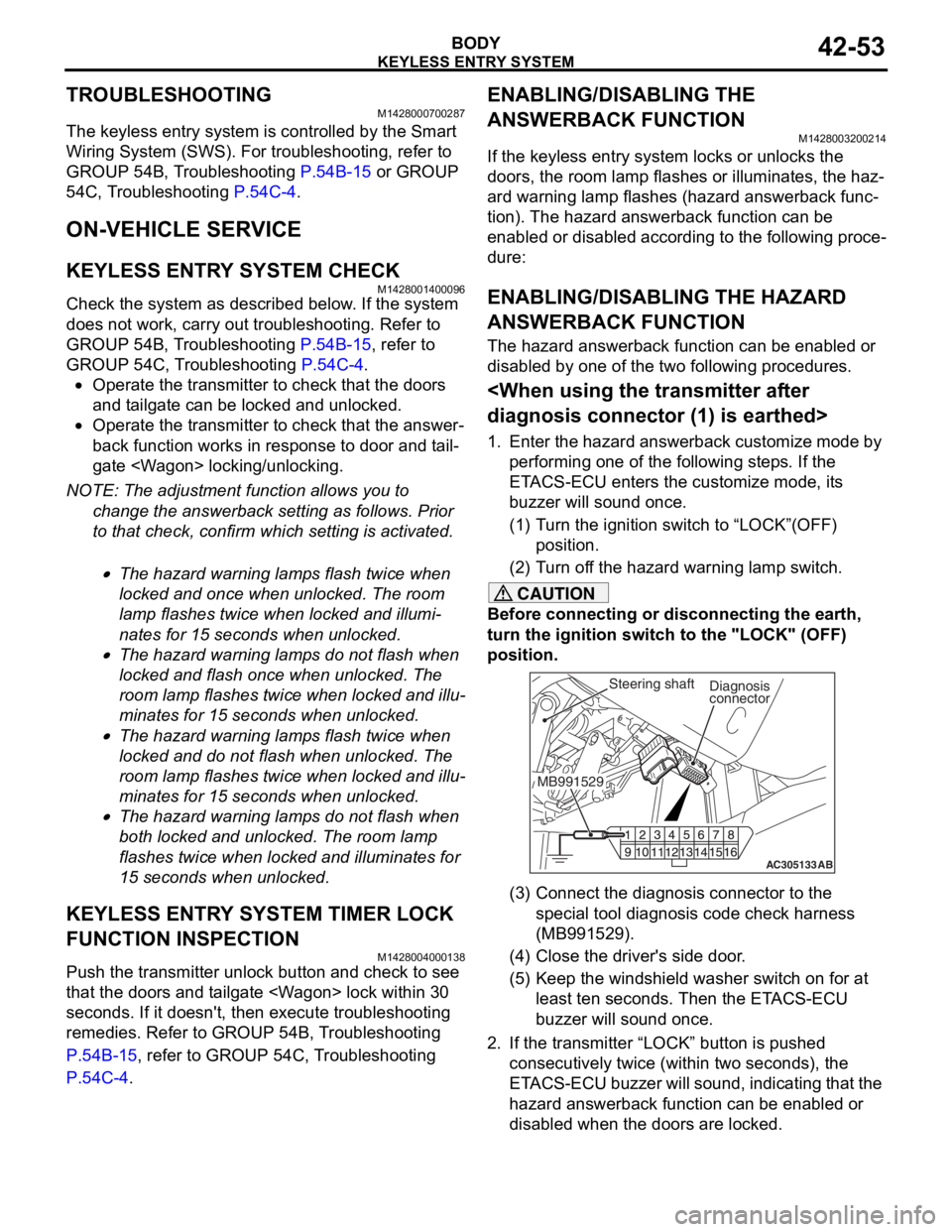
AC305133AB
Diagnosis
connector
MB991529Steering shaft
(3) Connect the diagnosis connector to the special tool diagnosis code check harness
(MB991529).
(4) Close the driver's side door.
(5) Keep the windshield washer switch on for at least ten seconds. Then the ETACS-ECU
buzzer will sound once.
2. If the transmitter “LOCK” button is pushed consecutively twice (wit hin two seconds), the
ETACS-ECU buzzer will sound, indicating that the
hazard answerback function can be enabled or
disabled when the doors are locked.
Page 326 of 800
KEYLESS ENTRY SYSTEM
BODY42-54
•Enable the hazard answerback function
when the doors are locked: The
ETACS-ECU buzzer will sound once.
•Disable the hazard answerback function
when the doors are locked: The
ETACS-ECU buzzer will sound twice.
3. If the transmitter “UNLOCK” button is pushed consecutively twice (wit hin two seconds), the
ETACS-ECU buzzer will sound, indicating that the
hazard answerback function can be enabled or
disabled when the doors are unlocked.
•Enable the hazard answerback function
when the doors are unlocked: The
ETACS-ECU buzzer will sound once.
•Disable the hazard answerback function
when the doors are unlocked: The
ETACS-ECU buzzer will sound twice.
4. Exit the hazard answer back customize mode by
observing one of the following steps.
(1) Disconnect diagnosis connector terminal (1) form the earth.
(2) Turn the ignition switch to position other then “LOCK”(OFF), or remove the ignition key.
(3) Open the driver's side door.
(4) Any other warning buzzer output occurs.
NOTE: If any operation is not done for at least three
minutes after the ETACS-ECU has entered the cus
-
tomize mode, the hazard answerback customize
mode will be canceled automatically.
connector>
1. Enter the hazard answerback customize mode by performing one of the following steps. If the
ETACS-ECU enters the customize mode, its
buzzer will sound once.
(1) Turn the ignition switch to “LOCK”(OFF) position.
(2) Turn off the hazard warning lamp switch.
CAUTION
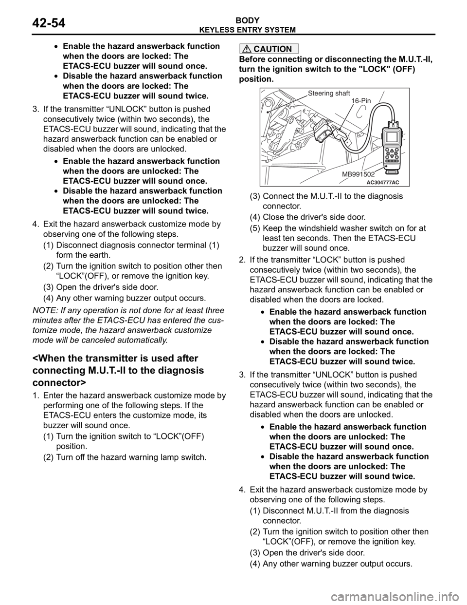
Before connecting or disconnecting the M.U.T.-II,
turn the ignition switch to the "LOCK" (OFF)
position.
AC304777
Steering shaft
ACMB991502
16-Pin
(3) Connect the M.U.T.-II to the diagnosis
connector.
(4) Close the driver's side door.
(5) Keep the windshield washer switch on for at least ten seconds. Then the ETACS-ECU
buzzer will sound once.
2. If the transmitter “LOCK” button is pushed consecutively twice (wit hin two seconds), the
ETACS-ECU buzzer will sound, indicating that the
hazard answerback function can be enabled or
disabled when the doors are locked.
•Enable the hazard answerback function
when the doors are locked: The
ETACS-ECU buzzer will sound once.
•Disable the hazard answerback function
when the doors are locked: The
ETACS-ECU buzzer will sound twice.
3. If the transmitter “UNLOCK” button is pushed consecutively twice (wit hin two seconds), the
ETACS-ECU buzzer will sound, indicating that the
hazard answerback function can be enabled or
disabled when the doors are unlocked.
•Enable the hazard answerback function
when the doors are unlocked: The
ETACS-ECU buzzer will sound once.
•Disable the hazard answerback function
when the doors are unlocked: The
ETACS-ECU buzzer will sound twice.
4. Exit the hazard answer back customize mode by
observing one of the following steps.
(1) Disconnect M.U.T.-II from the diagnosis
connector.
(2) Turn the ignition switch to position other then “LOCK”(OFF), or remove the ignition key.
(3) Open the driver's side door.
(4) Any other warning buzzer output occurs.
Page 327 of 800
KEYLESS ENTRY SYSTEM
BODY42-55
NOTE: If any operation is not done for at least three
minutes after the ETACS-ECU has entered the cus
-
tomize mode, the hazard answerback customize
mode will be canceled automatically.
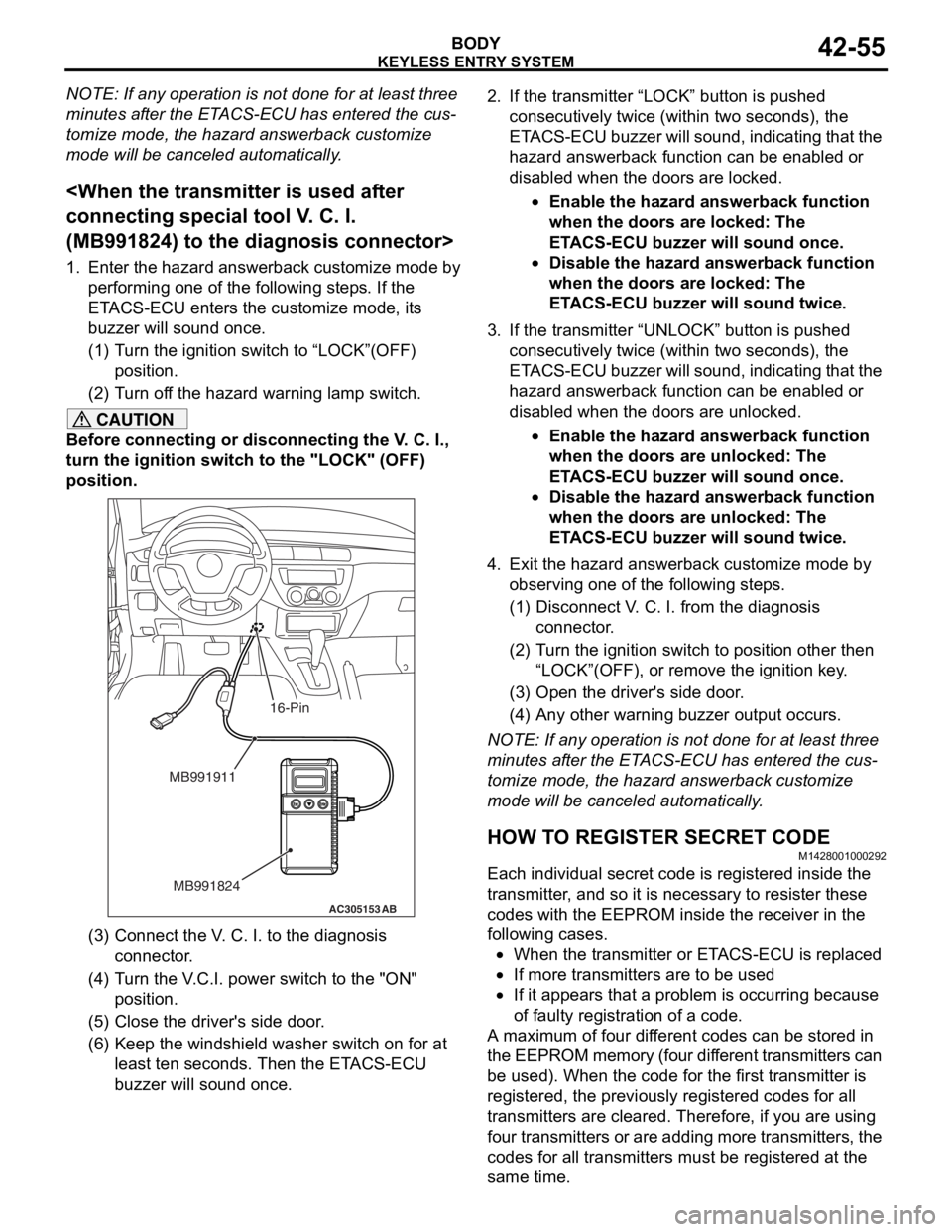
(MB991824) to the diagnosis connector>
1. Enter the hazard answerback customize mode by
performing one of the following steps. If the
ETACS-ECU enters the customize mode, its
buzzer will sound once.
(1) Turn the ignition switch to “LOCK”(OFF) position.
(2) Turn off the hazard warning lamp switch.
CAUTION
Before connecting or disconnecting the V. C. I.,
turn the ignition switch to the "LOCK" (OFF)
position.
AC305153AB
MB991911
MB991824
16-Pin
(3) Connect the V. C. I. to the diagnosis connector.
(4) Turn the V.C.I. power switch to the "ON" position.
(5) Close the driver's side door.
(6) Keep the windshield washer switch on for at least ten seconds. Then the ETACS-ECU
buzzer will sound once.
2. If the transmitter “LOCK” button is pushed
consecutively twice (wit hin two seconds), the
ETACS-ECU buzzer will sound, indicating that the
hazard answerback function can be enabled or
disabled when the doors are locked.
•Enable the hazard answerback function
when the doors are locked: The
ETACS-ECU buzzer will sound once.
•Disable the hazard answerback function
when the doors are locked: The
ETACS-ECU buzzer will sound twice.
3. If the transmitter “UNLOCK” button is pushed consecutively twice (wit hin two seconds), the
ETACS-ECU buzzer will sound, indicating that the
hazard answerback function can be enabled or
disabled when the doors are unlocked.
•Enable the hazard answerback function
when the doors are unlocked: The
ETACS-ECU buzzer will sound once.
•Disable the hazard answerback function
when the doors are unlocked: The
ETACS-ECU buzzer will sound twice.
4. Exit the hazard answer back customize mode by
observing one of the following steps.
(1) Disconnect V. C. I. from the diagnosis connector.
(2) Turn the ignition switch to position other then
“LOCK”(OFF), or remove the ignition key.
(3) Open the driver's side door.
(4) Any other warning buzzer output occurs.
NOTE: If any operation is not done for at least three
minutes after the ETACS-ECU has entered the cus
-
tomize mode, the hazard answerback customize
mode will be canceled automatically.
HOW TO REGISTER SECRET CODE
M1428001000292
Each individual secret code is registered inside the
transmitter, and so it is necessary to resister these
codes with the EEPROM insi de the receiver in the
following cases.
•When the transmitter or ETACS-ECU is replaced
•If more transmitters are to be used
•If it appears that a probl em is occurring because
of faulty registration of a code.
A maximum of four different codes can be stored in
the EEPROM memory (four different transmitters can
be used). When the code for the first transmitter is
registered, the previously registered codes for all
transmitters are cleared. Therefore, if you are using
four transmitters or are adding more transmitters, the
codes for all transmitters must be registered at the
same time.
Page 360 of 800

WINDSHIELD WIPER AND WASHER
EXTERIOR51-28
WINDSHIELD WIPER AND WASHER
GENERAL INFORMATIONM1511000100514
WINDSHIELD WIPER AND WASHER
OPERATION
Windshield Low-speed (and High-speed)
Wiper Operation
•If the windshield low-speed wiper switch is turned
to the ON position with the ignition switch at the
"ACC" or "ON" position, the column switch sends
a low-speed wiper ON and high-speed wiper OFF
signals to the front-ECU. This turns the wiper sig
-
nal on and the wiper speed control relay off
(low-speed), causing the wipers to operate at
low-speed.
•If the windshield high-speed wiper switch is
turned to the ON position, the column switch
sends a low-speed wiper OFF and high-speed
wiper ON signals to the front-ECU. This turns
both the wiper signal and the wiper speed control
relay on (high-speed), causing the wipers to
operate at high-speed.
NOTE: The windshield wiper speed is switchable
with the built-in wiper speed control relay.
High-speed operations take place when the wiper
speed control relay is set to "ON" and low-speed
operations take place when the wiper speed control
relay is set to "OFF".
Windshield Intermittent Wiper Operation
The ETACS-ECU calculates the wiper operation
interval according to the voltage signal sent from the
column switch. Then the ETACS-ECU sends a signal
to the front-ECU. The front-ECU determines the
wiper operation interval and turns on the wiper relay
signal relay. This causes the wiper auto stop relay to
turn on. Then the wiper auto stop relay will turn off
after the wipers reach the park position. This causes
the wiper signal relay and then the wipers to turn off.
If the wiper signal relay remains off for the wiper
operation interval, the relay turns on again, causing
the wipers to operate in intermittent mode.
Windshield Mist Wiper Operation
•If the windshield mist wipe r switch is turned to the
ON position with the ignition switch at the "ACC"
or "ON" position, the mist wiper high-speed oper
-
ation signal is sent to the front-ECU. This signal
turns on the wiper speed control relay, causing
the wipers to work at high-speed while the mist
switch is on.
•While the windshield mist wiper switch remains
turned on when the intermittent mode is still work
-
ing, the wipers work as the mist wiper. However,
the wipers return to the intermittent mode again
when the switch is changed back to "INT" posi
-
tion.
•To prevent the windshield mist wiper from operat-
ing when the windshield wiper switch is turned
OFF, the windshield mist wiper does not work for
0.5 second after the windshi eld intermittent wiper
switch, the windshield low-speed wiper switch
and the windshield high-speed wiper switch are
turned OFF.
Windshield Washer Operation
•If the windshield washer switch is turned to ON
position with the ignition sw itch at "ACC" or "ON"
position, the windshield wa sher ON signal is sent
to the front-ECU. After 0.3 second, the windshield
wiper signal turns on. After the windshield washer
switch signal turns off, the windshield wiper signal
turns off in three seconds.
•If the windshield washer switch is turned on while
the windshield wiper is at intermittent mode,
when the windshield washer switch is turned OFF
within 0.2 second, the wiper works only once to
perform mist operation by the windshield washer
switch. When the ON condi tion of the windshield
washer switch continues more than 0.2 second,
the wiper performs the same movement as nor
-
mal condition from the time when 0.2 second has
elapsed and then returns to the intermittent
motion.
SERVICE SPECIFICATION
M1511000300325
ItemStandard value
Windshield wiper blade park position mm34 ± 5
Page 392 of 800

ECU
COMPONENT LOCATIONS70-2
ECU
M1701000500311
NameSymbolNameSymbol
A/C-ECUEFront-ECUB
ABS-ECUAHeater control unit
Column switch (incorporating
Column-ECU)DImmobilizer-ECUG
Engine-A/T-ECU IPower window main switch
(incorporating ECU)K
Engine-ECU
(incorporating ECU)J
ETACS-ECUFSRS-ECUH
Cooling fan motor drive control unitC
AC301182
DE
AB
C
FGHI
AB
DE
AB
C
FGHI
Page 394 of 800
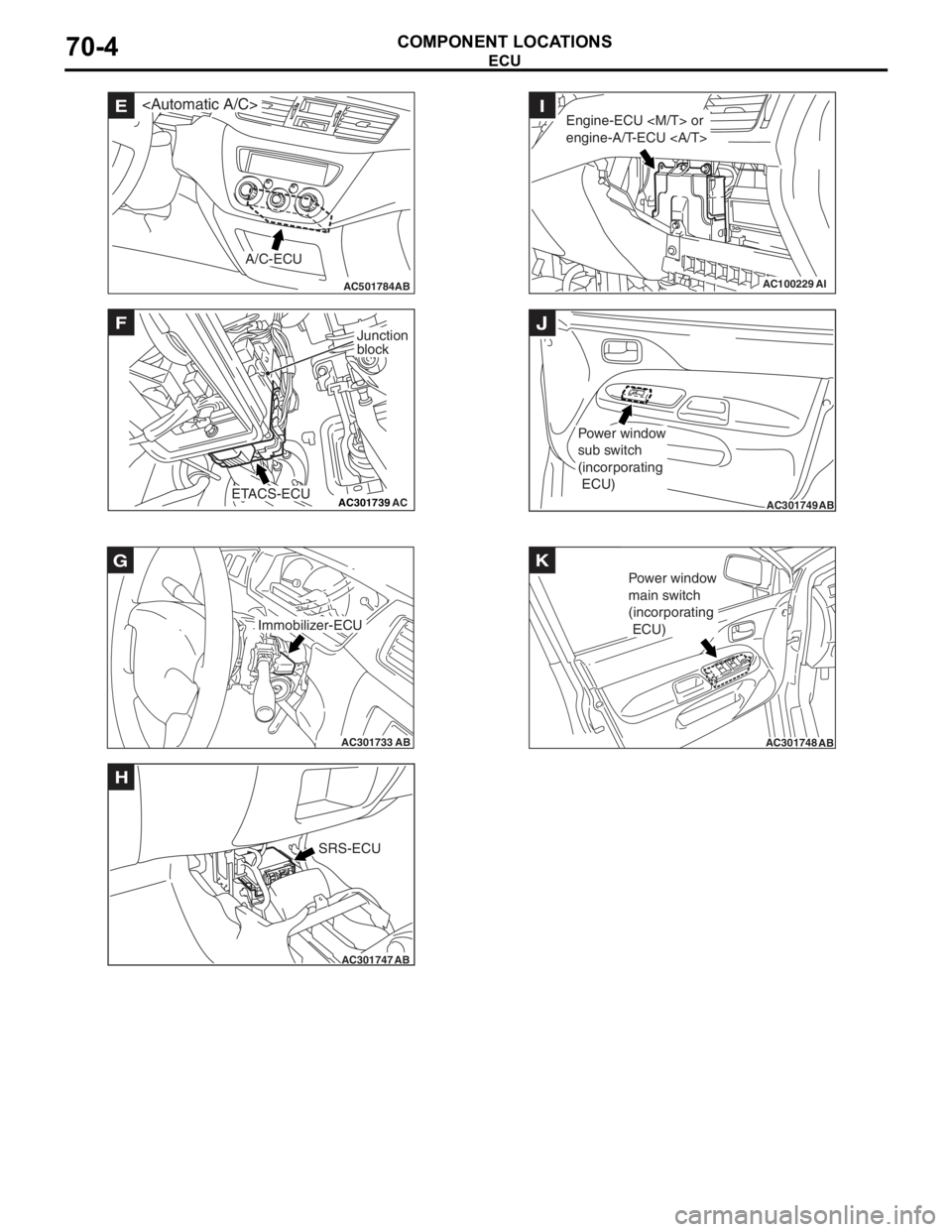
AC501784AB
E
A/C-ECU
AC301739AC
F
ETACS-ECU
Junction
block
AC301733AB
Immobilizer-ECU
G
AC301747AB
SRS-ECU
H
AC100229AI
Engine-ECU
engine-A/T-ECU I
AC301749AB
Power window
sub switch
(incorporating
ECU)
J
AC301748AB
Power window
main switch
(incorporating
ECU)
K
ECU
COMPONENT LOCA
TIONS70-4
Page 441 of 800
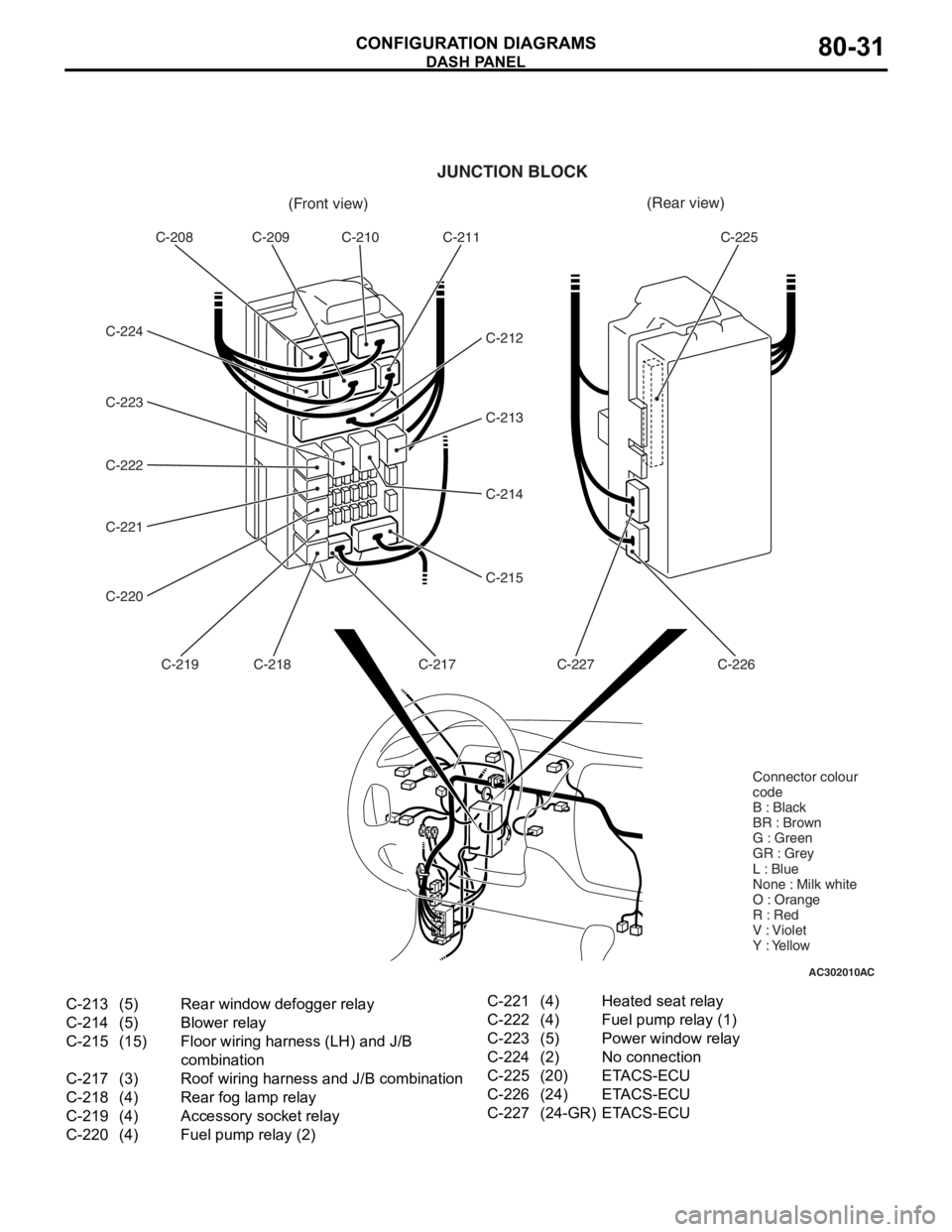
AC302010AC
(Front view)(Rear view)
C-208 C-209 C-210 C-211
C-212
C-213
C-214
C-215
C-217
C-218
C-219
C-220 C-221 C-222 C-223 C-224 C-225
C-226
C-227
JUNCTION BLOCK
Connector colour
code
B : Black
BR : Brown
G : Green
GR : Grey
L : Blue
None : Milk white
O : Orange
R : Red
V : Violet
Y : Yellow
C-213(5)Rear window defogger relay
C-214(5)Blower relay
C-215(15)Floor wiring harness (LH) and J/B
combination
C-217(3)Roof wiring harness and J/B combination
C-218(4)Rear fog lamp relay
C-219(4)Accessory socket relay
C-220(4)Fuel pump relay (2)
C-221(4)Heated seat relay
C-222(4)Fuel pump relay (1)
C-223(5)Power window relay
C-224(2)No connection
C-225(20)ETACS-ECU
C-226(24)ETACS-ECU
C-227(24-GR)ETACS-ECU
DASH P ANEL
CONF IGURA TION D I A G RA MS80-31
Page 447 of 800
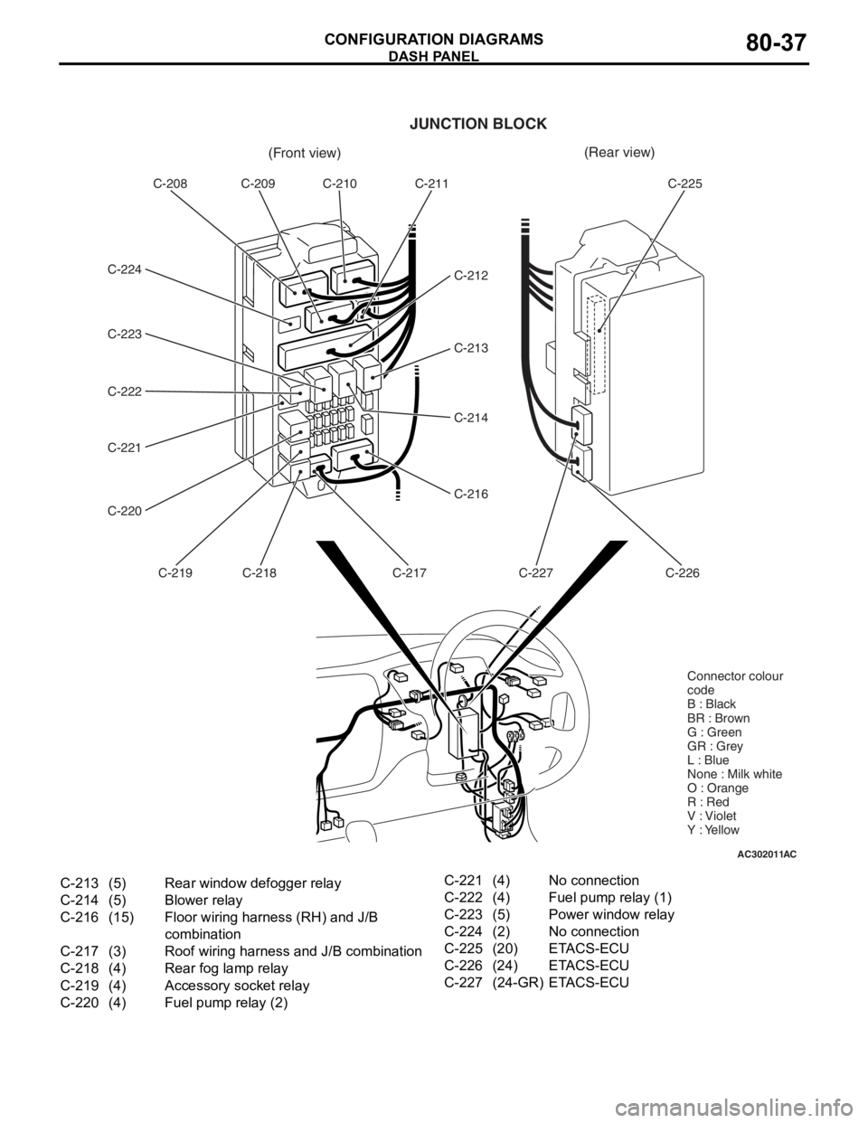
AC302011AC
(Front view)(Rear view)
C-208 C-209 C-210 C-211
C-212
C-213
C-214
C-216
C-217
C-218
C-219
C-220 C-221 C-222 C-223 C-224 C-225
C-226
C-227
JUNCTION BLOCK
Connector colour
code
B : Black
BR : Brown
G : Green
GR : Grey
L : Blue
None : Milk white
O : Orange
R : Red
V : Violet
Y : Yellow
C-213(5)Rear window defogger relay
C-214(5)Blower relay
C-216(15)Floor wiring harness (RH) and J/B
combination
C-217(3)Roof wiring harness and J/B combination
C-218(4)Rear fog lamp relay
C-219(4)Accessory socket relay
C-220(4)Fuel pump relay (2)
C-221(4)No connection
C-222(4)Fuel pump relay (1)
C-223(5)Power window relay
C-224(2)No connection
C-225(20)ETACS-ECU
C-226(24)ETACS-ECU
C-227(24-GR)ETACS-ECU
DASH P ANEL
CONF IGURA TION D I A G RA MS80-37
Page 469 of 800

J/B
CIRCUIT DIAGRAMS90-5
NOTE: .
•The triangle mark on the relay housing should face that on the J/B and the relay box.
AC209083
Front side
C-208
C-222C-224
C-220C-221
C-219
C-217 C-218C-212C-211 C-210
C-209
Fuel pump
relay (1)
Fuel pump
relay (2) Heated seat
relay
Rear fog
lamp relay No connection
To roof wiring
harnessTo floor wiring
harnessRear
window
defogger
relayBlower
relay To instrument panel
wiring harnessTo instrument panel
wiring harness
Power
window
relayETACS-ECU
C-225
AM
Rear side
C-223C-214C-213
1
23
4
Fuses
(No.1 to 20)
1
23
4 1
23
4 1
23
4 1
23
4
Accessory
socket relay
1
7
132
8
143
9
154
10
165
11
176
12
20
19
18
C-215
C-216
Page 482 of 800

CENTRALIZED JUNCTION
CIRCUIT DIAGRAMS90-18
CENTRALIZED JUNCTION
M1901000301477
FUSIBLE LINK AND FUSE
ENGINE COMPARTMENT
No.Power supply circuitNameRated
capacity (A)Housing
colourLoad circuit
1Battery/ Alternator
(Fusible link No.26)Fusible
link60YellowFuse No.15, 16, 18, 19, 20 (in junction
block) circuit
250RedFan controller
360YellowABS-ECU
440GreenIgnition switch circuit
530PinkPower window main switch and power
window sub switch
6Fuse15BlueFront fog lamp, front fog lamp
indicator lamp, front fog lamp relay
and spare connector (for front fog
lamp)
710RedHorn relay and horn
820YellowAir cleaner air flow sensor, camshaft
position sensor, emission solenoid
valve (EGR system), emission
solenoid valve (purge control system),
engine-A/T-ECU, engine-ECU, engine
control oxygen sensor, engine control
relay, engine crank angle sensor, fan
control relay, fuel injector, ignition coil
relay, immobilizer-ECU and throttle
body idle speed control servo
910RedA/C compressor
1015BlueABS-ECU, engine-A/T-ECU, high
mount stop lamp and rear combination
lamp
1115BlueAccessory socket
127.5BrownAlternator
1310RedETACS-ECU, front turn signal lamp,
rear combination lamp, side turn
signal lamp and turn signal indicator
lamp
1420YellowA/T control solenoid valve assembly
and engine-A/T-ECU
1515BlueFuel pump
16Front-ECU
(Headlamp relay: HI)10RedHeadlamp (RH)
1710RedHeadlamp (LH) and high beam
indicator lamp
18Front-ECU
(Headlamp relay: LO)10RedHeadlamp (RH)
1910RedHeadlamp (LH), headlamp assembly
and headlamp levelling switch