brake rotor MITSUBISHI LANCER IX 2006 Service Manual
[x] Cancel search | Manufacturer: MITSUBISHI, Model Year: 2006, Model line: LANCER IX, Model: MITSUBISHI LANCER IX 2006Pages: 800, PDF Size: 45.03 MB
Page 140 of 800

FRONT AXLE HUB ASSEMBLY
FRONT AXLE26-8
FRONT AXLE HUB ASSEMBLY
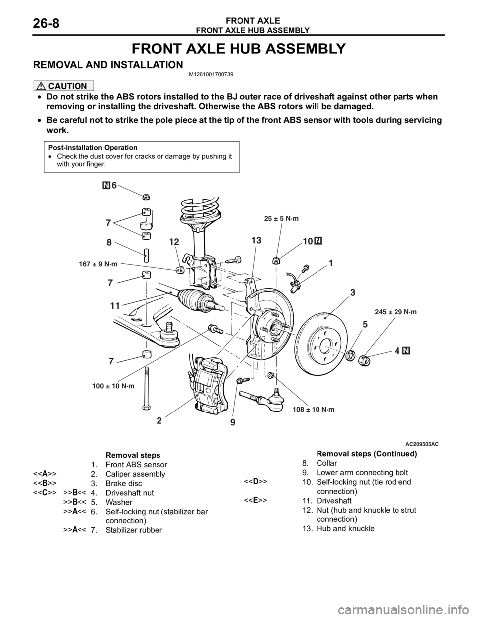
REMOVAL AND INSTALLATIONM1261001700739
CAUTION
•Do not strike the ABS rotors installed to the BJ outer race of driveshaft against other parts when
removing or installing the driveshaft. Otherwise the ABS rotors will be damaged.
•
Post-installation Operation
•Check the dust cover for cracks or damage by pushing it
with your finger.
AC209505
N
N
N
5
4
3
1
8
10
9
2
7
6
167 ± 9 N·m 25 ± 5 N·m
108 ± 10 N·m 245 ± 29 N·m
100 ± 10 N·m
AC
7 7
11 12
13
Removal steps
1. Front ABS sensor
<> 2. Caliper assembly
<> 3. Brake disc
<
>>B<<5. Washer
>>A<<6.Self-locking nut (stabilizer bar
connection)
>>A<<7.Stabilizer rubber
8.Collar
9. Lower arm connecting bolt
<
connection)
<
12.Nut (hub and knuckle to strut
connection)
13.Hub and knuckle
Be careful not to strike the pole piece at the tip of the front ABS sensor with tools during servicing
work.
Removal steps (Continued)
Page 146 of 800

DRIVESHAFT ASSEMBLY
FRONT AXLE26-14
DRIVESHAFT ASSEMBLY
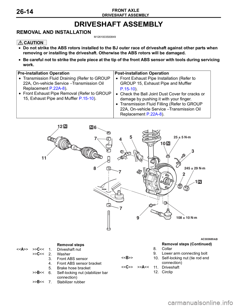
REMOVAL AND INSTALLATIONM1261003500849
CAUTION
•Do not strike the ABS rotors installed to the BJ outer race of driveshaft against other parts when
removing or installing the driveshaft. Otherwise the ABS rotors will be damaged.
•
Pre-installation Operation
•Transmission Fluid Draining (Refer to GROUP
22A, On-vehicle Service
− Transmission Oil
Replacement
P.22A-8).
•Front Exhaust Pipe Removal (Refer to GROUP
15, Exhaust Pipe and Muffler
P.15-10).
Post-installation Operation
•Front Exhaust Pipe Installation (Refer to
GROUP 15, Exhaust Pipe and Muffler
P.15-10).
•Check the Ball Joint Dust Cover for cracks or
damage by pushing it with your finger.
•Transmission Fluid Filling (Refer to GROUP
22A, On-vehicle Service
− Transmission Oil
Replacement
P.22A-8).
AC303689AB
9
N
N
NN
10
7
4
3
2 1
25 ± 5 N·m
245 ± 29 N·m
108 ± 10 N·m
8
5
6
11 12
77
Removal steps
<>>>C<<1.Driveshaft nut
>>C<<2.Washer
3.Front ABS sensor
4.Front ABS sensor bracket
5.Brake hose bracket
>>B<<6.Self-locking nut (stabilizer bar
connection)
>>B<<7.Stabilizer rubber
8.Collar
9.Lower arm connecting bolt
<>10.Self-locking nut (tie rod end
connection)
<
12.Circlip
Be careful not to strike the pole piece at the tip of the front ABS sensor with tools during servicing
work.
Removal steps (Continued)
Page 161 of 800

REAR AXLE HUB ASSEMBLY
REAR AXLE27-5
REAR AXLE HUB ASSEMBLY
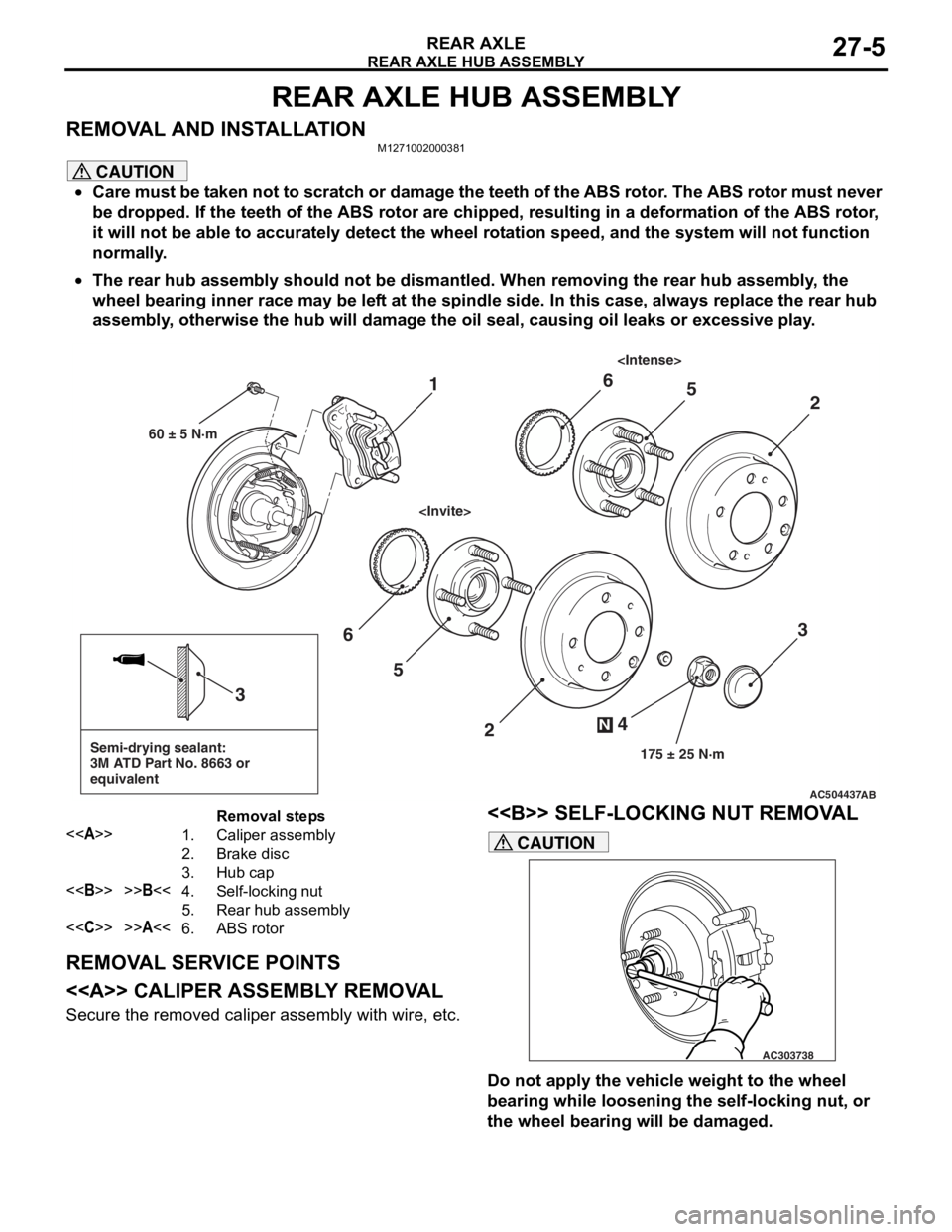
REMOVAL AND INSTALLATIONM1271002000381
CAUTION
•Care must be taken not to scratch or damage the teeth of the ABS rotor. The ABS rotor must never
be dropped. If the teeth of the ABS rotor are chipped, resulting in a deformation of the ABS rotor,
it will not be able to accurately detect the wheel rotation speed, and the system will not function
normally.
•
AC504437
Semi-drying sealant:
3M ATD Part No. 8663 or
equivalent
2
3
5
6
4
N
175 ± 25 N·m
3
AB
1
60 ± 5 N·m
2
56
Removal steps
<>1.Caliper assembly
2.Brake disc
3.Hub cap
<>>>B<<4.Self-locking nut
5.Rear hub assembly
<
The rear hub assembly should not be dismantled. When removing the rear hub assembly, the
wheel bearing inner race may be left at the spindle side. In this case, always replace the rear hub
assembly, otherwise the hub will damage the oil seal, causing oil leaks or excessive play.
REMOVAL SERVICE POINTS
<> CALIPER ASSEMBLY REMOVAL
Secure the removed caliper assembly with wire, etc.
<> SELF-LOCKING NUT REMOVAL
AC303738
CAUTION
Do not apply the vehicle weight to the wheel
bearing while loosening the self-locking nut, or
the wheel bearing will be damaged.
Page 223 of 800

LUBRICANTS
PARKING BRAKES36-3
LUBRICANTS
M1361000400293
ItemSpecified lubricant
Rear brake shoe and backing plate contact surfaceBrake grease SAE J310, NLGI No.1
Rear brake shoe assembly
Rear brake shoe slack adjuster
ON-VEHIC LE SER VI CE
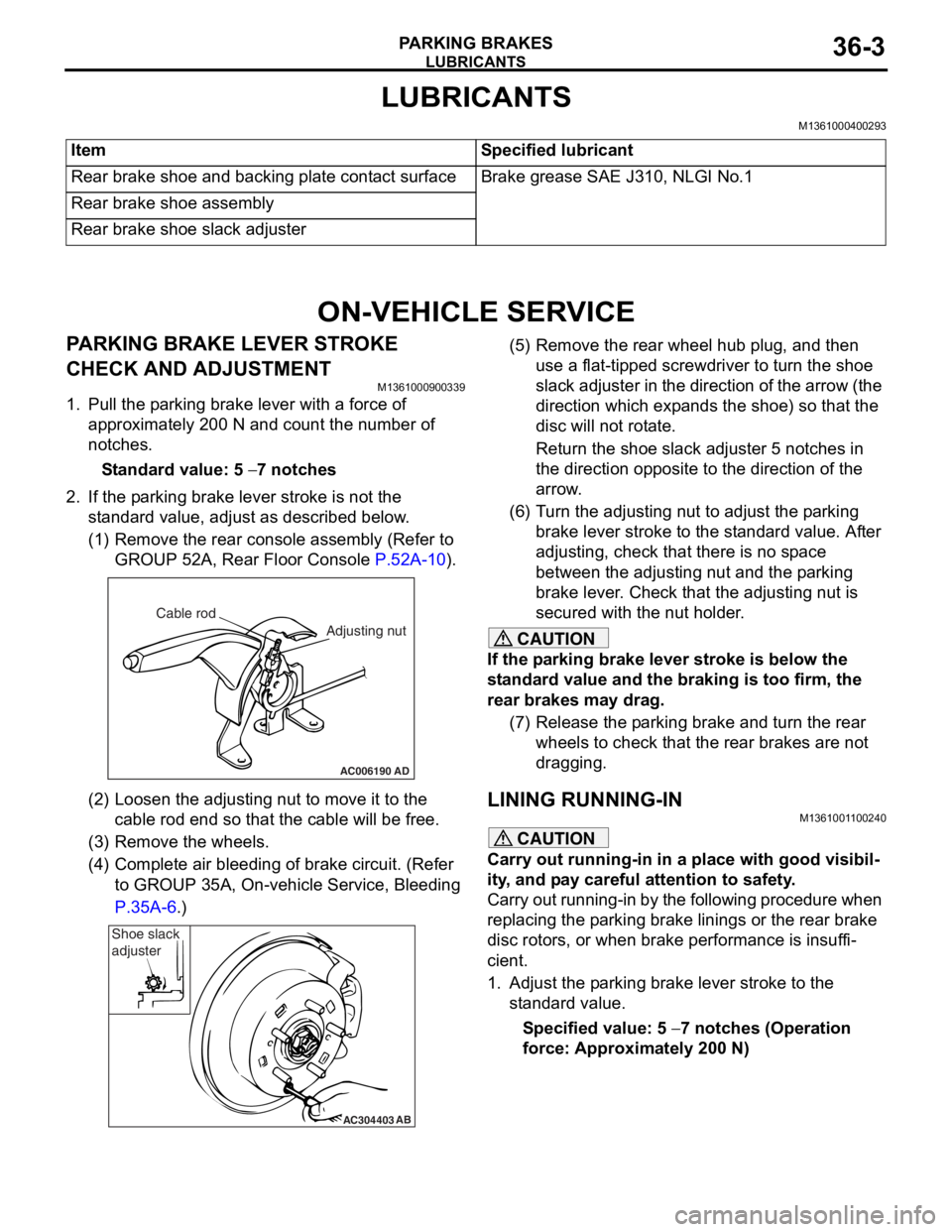
PARKING BRAKE LE VER STROKE
CHECK AND ADJUSTMENT
M13610009 0033 9
1.Pull the p a rkin g brake le ver wit h a force of
ap proxima t ely 200 N an d co unt the number of
no tche s.
St andard va lue: 5 − 7 notches
2.If the p a rking b r ake leve r stro ke is no t the
st a ndard valu e, adjust as de scribed below .
(1)R emove the rear console a sse mbly (Refer to
GROUP 5 2 A, Rear Floor Console
P.52A-10).
AC006190
Cable rod
Adjusting nut
AD
(2)Loosen th e adjusting nu t to move it to th e
cab l e rod end so tha t the cable will be fre e .
(3)R emove the wheels.
(4)C omplete a i r bleedin g of b r ake circuit. (Re f er
to GROUP 35A, On-ve h icle Service, Blee ding
P.35A-6.)
AC304403AB
Shoe slack
adjuster
(5
) R emove the rear whee l hub plug , and then
use a flat-tipped screwdriver to turn the shoe
slack ad juster in the direction of the arrow (the
dire ctio n which exp a nds the shoe) so that the
disc will no t rot a te.
Return the sh oe slack adjust e r 5 not ches in
the d
i rection opposite t o the d i rection of the
arrow
.
(6) T urn th e adjusting nut to adjust the p a rking
brake le ver stroke to the st anda rd value. Af ter
adjusting, check that there is n o sp ace
between the a d justing nut an d the p a rking
brake le ver . Che ck that th e adjusting nut is
secured with the nut ho lder .
CAUTION
If the parking brake lever stroke is below the
standard value and the braking is too firm, the
rear brakes may drag.
(7) Release the parking brake and turn the rear wheels to check that t he rear brakes are not
dragging.
LINING RUNNING-INM1361001100240
CAUTION
Carry out running-in in a place with good visibil-
ity, and pay careful attention to safety.
Carry out running-in by the following procedure when
replacing the parking brake linings or the rear brake
disc rotors, or when brake performance is insuffi
-
cient.
1. Adjust the parking brake lever stroke to the standard value.
Specified value: 5 − 7 notches (Operation
force: Approximately 200 N)