Junction MITSUBISHI LANCER IX 2006 Service Manual
[x] Cancel search | Manufacturer: MITSUBISHI, Model Year: 2006, Model line: LANCER IX, Model: MITSUBISHI LANCER IX 2006Pages: 800, PDF Size: 45.03 MB
Page 204 of 800
ON-VEHICLE SERVICE
REAR SUSPENSION34-6
ON-VEHICLE SERVICE
REAR WHEEL ALIGNMENT CHECK AND
ADJUSTMENT
M1341011000372
Measure wheel alignment with an alignment equip-
ment on level earth.
The rear suspension, wheels, and tyres should be
serviced to the normal condition prior to wheel align
-
ment measurement.
CAMBER
Standard value: −0°40' ± 0°30' (Left/right devi-
ation within 30')
CAUTION
Never subject the wheel bearings to the vehicle
load when the rear wheel hub nuts (self-locking
nuts) or special tool wheel alignment gauge
attachment (MB991014) are loosened.
NOTE:
AC001079
MB991014
AG
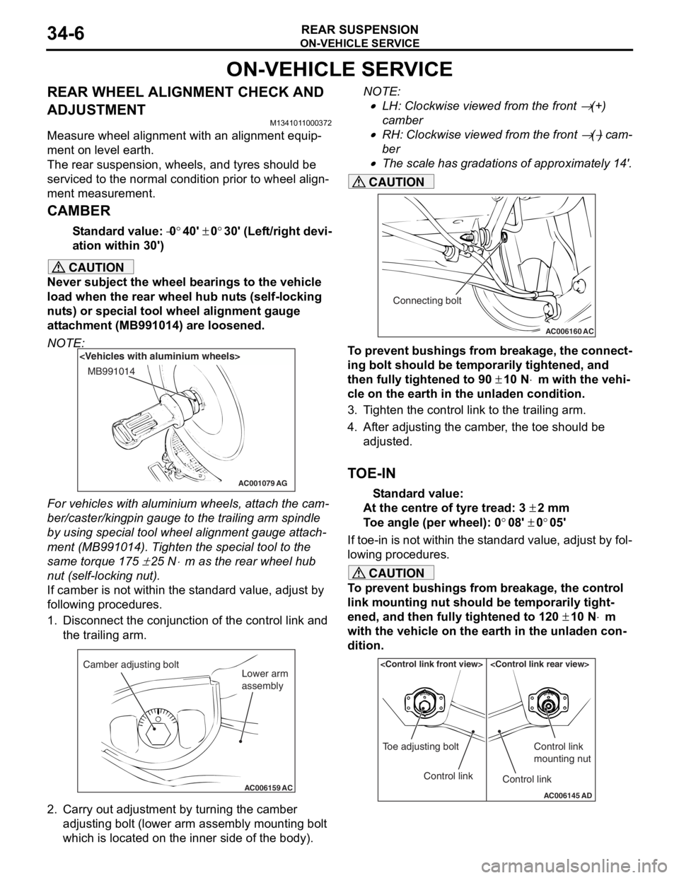
For vehicles with aluminium wheels, attach the cam-
ber/caster/kingpin gauge to the trailing arm spindle
by using special tool wheel alignment gauge attach
-
ment (MB991014). Tighten the special tool to the
same torque 175
± 25 N⋅m as the rear wheel hub
nut (self-locking nut).
If camber is not within the standard value, adjust by
following procedures.
1. Disconnect the conjunction of the control link and the trailing arm.
AC006159 AC
Camber adjusting bolt
Lower arm
assembly
2. Carry out adjustment by turning the camber
adjusting bolt (lower arm assembly mounting bolt
which is located on the inner side of the body).
NOTE: .
•LH: Clockwise viewed from the front → (+)
camber
•RH: Clockwise viewed from the front → (−) cam-
ber
•
AC006160 AC
Connecting bolt
The scale has gradations of approximately 14'.
CAUTION
To prevent bushings from breakage, the connect-
ing bolt should be temporarily tightened, and
then fully tightened to 90
± 10 N⋅m with the vehi-
cle on the earth in the unladen condition.
3. Tighten the control link to the trailing arm.
4. After adjusting the camber, the toe should be
adjusted.
TOE-IN
Standard value:
At the centre of tyre tread: 3 ± 2 mm
Toe angle (per wheel): 0°08' ± 0°05'
If toe-in is not within the standard value, adjust by fol-
lowing procedures.
CAUTION
To prevent bushings from breakage, the control
link mounting nut should be temporarily tight
-
ened, and then fully tightened to 120 ± 10 N⋅m
with the vehicle on the earth in the unladen con
-
dition.
AC006145 AD
Control link
Toe adjusting boltControl link
Control link
mounting nut
Page 301 of 800
DOOR
BODY42-29
3. If the operation current is outside the standard value, refer to GROUP 54B, Troubleshooting
P.54B-15, refer to GROUP 54C, Troubleshooting
P.54C-4.
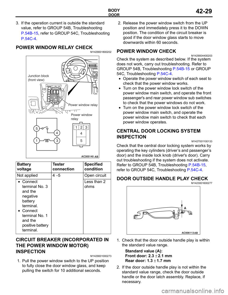
POWER WINDOW RELAY CHECKM1429001800202
AC305140
123
4
5
1 3
4
5
AB
Junction block
(front view)
Power window relayPower window
relay
Bat t ery
voltage
Teste r
co
nnectionSpecified
condition
Not applied4 − 5Ope n ci rcui t
•Connect
te
rmin al No. 3
an
d the
ne
gative
ba
ttery
te
rmin al.
•Connect
te
rmin al No. 1
an
d the
positive batt
e ry
te
rmin al.
Less than 2
ohms
CIRCUIT BREAKER (INCORPORA T ED IN
THE POW
E R W I NDOW MOT O R)
INSPECTION
M14290010 0027 3
1.Pull the p o wer windo w switch to th e UP position
to f u lly close the do or windo w g l ass, an d ke ep
pullin g the switch for 1 0 addition al secon d s.
2.Rele ase the power window switch from t he UP
position an d immediately pre ss it to t he DOW N
position. Th e con d ition of the circu i t brea ker is
goo d if t he doo r window g l ass st art s to mo ve
downward s with in 60 seconds.
POWER WI NDOW CHECKM14290044 0020 3
Check the system a s de scribed b e low . I f the system
does not work, car
r y out troublesh ootin g. Refer to
GROUP 54
B, T r ouble s hoo ting
P.54B-15 or GROUP
54C, T r oublesh ootin g P.54C-4.
•Operate the powe r wind ow switch of e a ch se at to
check that
the power window works.
•Tu rn o n the power wind ow lock switch of the
power wind
ow main swit ch, and ope rate the front
p
a ssenger's and rear power window su b switches
to check th
at the p o wer windo ws do n o t work.
•Tu rn o n the power wind ow lock switch of the
power
window main switch, and operate the
power
window main switch to check tha t each
power window
op erates.
CENTRAL DOOR LOCKING SYSTEM
INSPECTION
M142700 1 1 0013 3
Check that th e ce ntral door locking system wo rks by
op
er atin g th e key cylin de rs (d rive r ’ s an d p a sse n g e r ’ s
door) an
d the inside lock kno b (driver's door). Ca rry
out trou
bleshooting if the system does not activate.
Re
fer to GROUP 54B, T r ou bleshooting
P.54B-15,
refer to GROUP 54 C, T r o uble s hoo ting P.54C-4.
DOOR OUTSIDE HANDLE PL A Y CHECKM14230016 0027 7
AC006113
AB
A
1.Check t hat the door o u t s ide handle play is with in
th e st and ard va lue range.
St andard va lue (A):
Fron t door: 2.3 ± 2.1 m m
Rear door: 1.3 ± 1.7 mm
2. If the do or out side ha ndle play is not wit h in th e
st a ndard valu e rang e, ch eck the do or out side
h andle or the door latch assemb ly . Replace, if
ne c e ss a r y .
Page 377 of 800
DOOR MIRROR
EXTERIOR51-45
STEP 2. Connector check: C-212 junction block
connector
AC304913
21716151718
201912345
623 222425282627981011141213
Connector: C-212
Harness side
AB
Junction block (Front view)
Q: Is t h e che c k r esu lt n o rmal?
YES : Intermittent malfun ctio n (Refer to GROUP
00
− Ho w to Cope wit h Intermitte nt
Ma
lfunction
P.00-5).
NO : Repa ir th e defective connector .
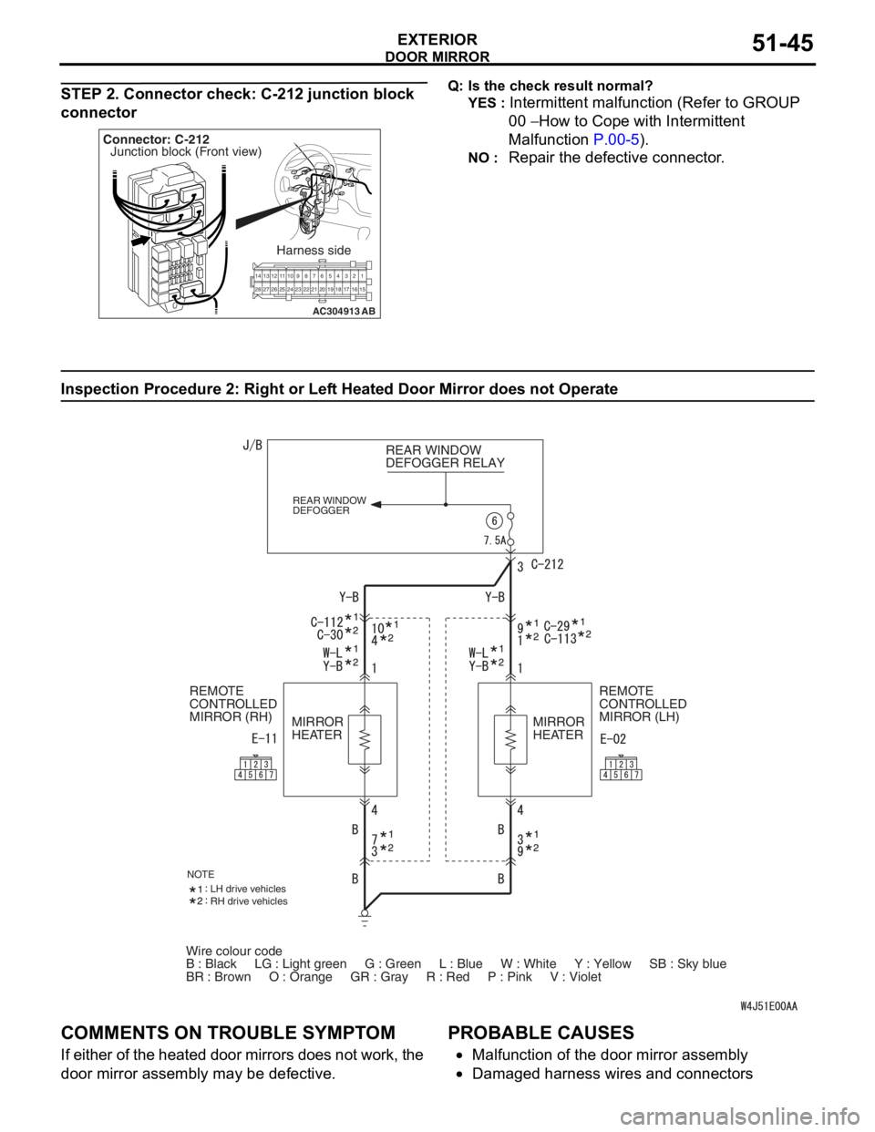
Inspection Procedure 2 : Ri ght or Lef t Hea t ed Door Mirror does not Operate
Wire colour code
B : Black LG : Light green G : Green L : Blue W : White \
Y : Yellow SB : Sky blue
BR : Brown O : Orange GR : Gray R : Red P : Pink V :\
Violet REAR WINDOW
DEFOGGER RELAY
REAR WINDOW
DEFOGGER
REMOTE
CONTROLLED
MIRROR (LH)
REMOTE
CONTROLLED
MIRROR (RH)
MIRROR
HEATER MIRROR
HEATER
NOTELH drive vehicles
RH drive vehicles
COMM
ENT S ON TROUBL E SYMPT O M
If eit her of t he hea ted d oor mirrors does n o t work, the
door mirror a
sse mbly may b e defe c tive.
PROBABLE CAUSES
•Malfunctio n of th e door mirro r assemb ly
•Damaged ha rness wires and con necto rs
Page 379 of 800
DOOR MIRROR
EXTERIOR51-47
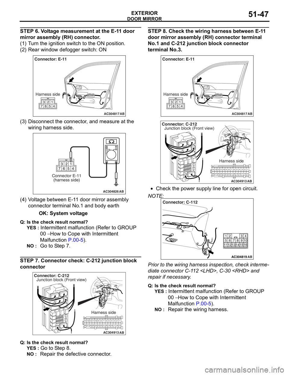
STEP 6. Voltage measurement at the E-11 door
mirror assembly (RH) connector.
(1) Turn the ignition switch to the ON position.
(2) Rear window defogger switch: ON
AC304817
Connector: E-11Harness side
AB
(3) D isconn ect t he co nnector , an d me asure at the
wiring harn e ss side.
AC304826
Connector E-11(harness side)
AB
(4) V olt a g e between E-1 1 door mirror assembly
co nnector termina l No.1 a nd bod y ea rth
OK: System vo lt age
Q: Is the check result normal?
YES : Intermittent ma lfun ctio n (Refer to GROUP
00
− Ho w t o Cope wit h Intermitte nt
Malfunction
P.00-5).
NO : Go to S t ep 7.
STEP 7. Co nnector ch eck: C-212 junction block
connecto
r
AC304913
21716151718
201912345
623 222425282627981011141213
Connector: C-212
Harness side
AB
Junction block (Front view)
Q : Is the check result normal?
YES : Go to S t ep 8.
NO : Repa ir the defective connector .
STEP 8 . Check the wiring harness b e twee n E-1 1
door mirror assem
bly (RH) conne ctor terminal
No.
1 and C-21 2 junctio n block connec tor
terminal No.3
.
AC304817
Connector: E-11
Harness side
AB
AC304913
21716151718
201912345
623 222425282627981011141213
Connector: C-212
Harness side
AB
Junction block (Front view)
•Check th e power supply line fo r open circuit.
NOTE:
AC304819
Connector: C-112
AB
Prior to the wiring harness insp ection, check interme-
diate connector C-1 1 2
rep
a ir if necessary .
Q:Is t h e che c k r esu lt n o rmal?
YES : Intermittent malfun ctio n (Refer to GROUP
00
− Ho w to Cope wit h Intermitte nt
Ma
lfunction
P.00-5).
NO : Repa ir th e wirin g harne ss.
Page 381 of 800
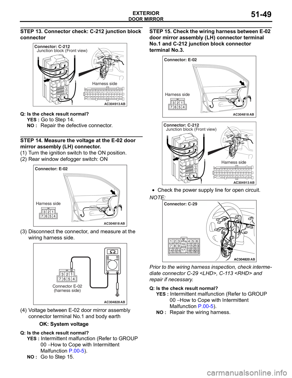
DOOR MIRROR
EXTERIOR51-49
STEP 13. Connector check: C-212 junction block
connector
AC304913
21716151718
201912345
623 222425282627981011141213
Connector: C-212
Harness side
AB
Junction block (Front view)
Q : Is the check result normal?
YES : Go to S t ep 14 .
NO : Repa ir the defective connector .
STEP 14 . Me asure the volt age at the E-02 door
mirror a
ssembl y (LH) conne ctor .
(1)T urn t he ig nition switch to the ON positio n.
(2)R ear win dow defo gger switch : ON
AC304818
Connector: E-02
Harness side
AB
(3) D isconn ect t he co nnector , an d me asure at the
wiring harn e ss side.
AC304828
Connector E-02(harness side)
AB
(4) V olt a g e between E-02 doo r mirror assembly
co nnector termina l No.1 a nd bod y ea rth
OK: System vo lt age
Q: Is the check result normal?
YES : Intermittent ma lfun ctio n (Refer to GROUP
00
− Ho w t o Cope wit h Intermitte nt
Malfunction
P.00-5).
NO : Go to S t ep 15 .
STEP 1 5 . Chec k the wiring ha rnes s betwe en E-02
door mirror assem
bly (LH) con nector termina l
No.
1 and C-21 2 junctio n block connec tor
terminal No.3
.
AC304818
Connector: E-02
Harness side
AB
AC304913
21 716151718
201912345
623 222425282627981011141213
Connector: C-212
Harness side
AB
Junction block (Front view)
•Check th e power supply line fo r open circuit.
NOTE:
AC304820
Connector: C-29
AB
Prior to the wiring harness insp ection, check interme-
diate connector C-29
rep
a ir if necessary .
Q:Is t h e che c k r esu lt n o rmal?
YES : Intermittent malfun ctio n (Refer to GROUP
00
− Ho w to Cope wit h Intermitte nt
Ma
lfunction
P.00-5).
NO : Repa ir th e wirin g harne ss.
Page 394 of 800
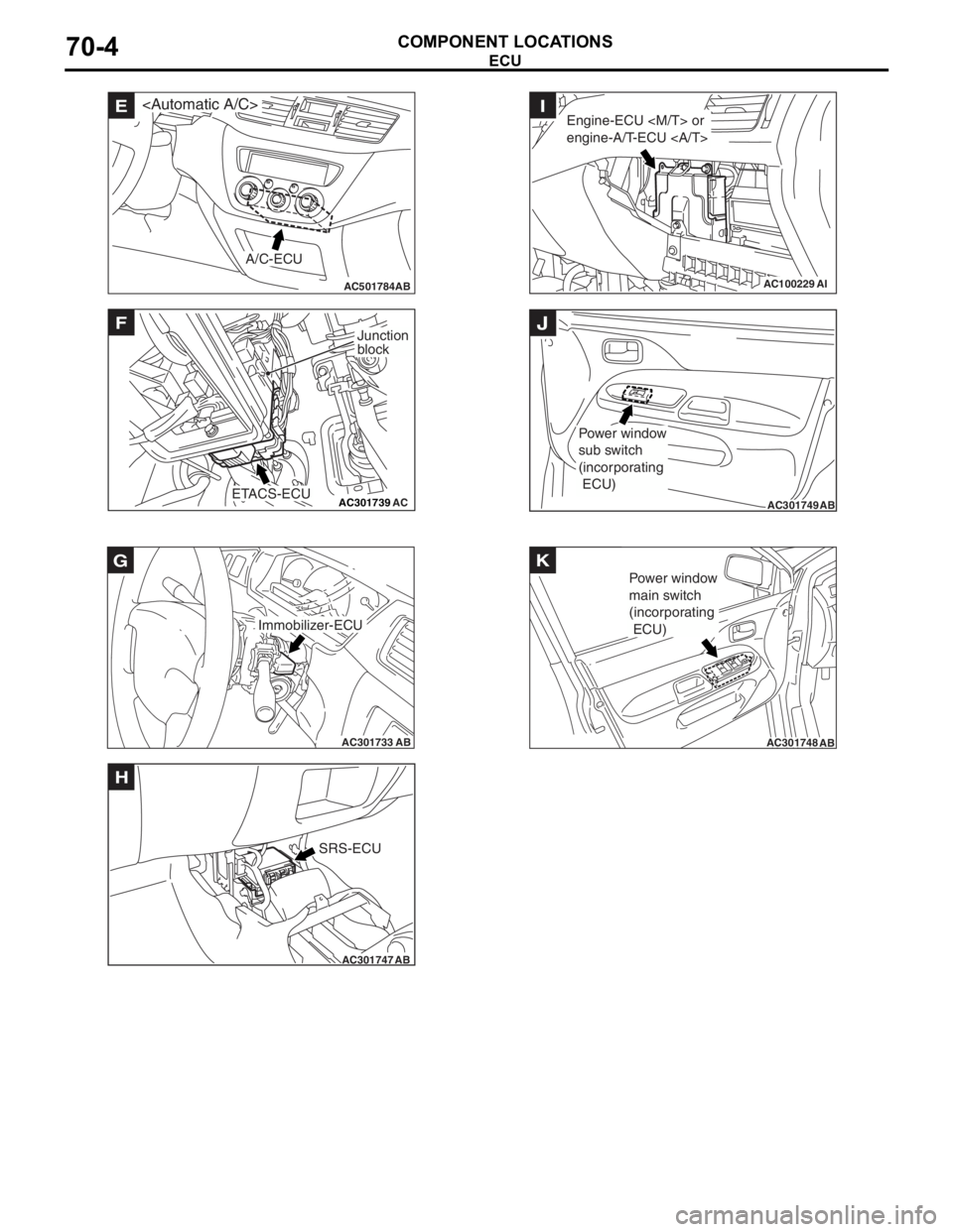
AC501784AB
E
A/C-ECU
AC301739AC
F
ETACS-ECU
Junction
block
AC301733AB
Immobilizer-ECU
G
AC301747AB
SRS-ECU
H
AC100229AI
Engine-ECU
engine-A/T-ECU I
AC301749AB
Power window
sub switch
(incorporating
ECU)
J
AC301748AB
Power window
main switch
(incorporating
ECU)
K
ECU
COMPONENT LOCA
TIONS70-4
Page 401 of 800
FUSIBLE LINK AND FUSE
COMPONENT LOCATIONS70-11
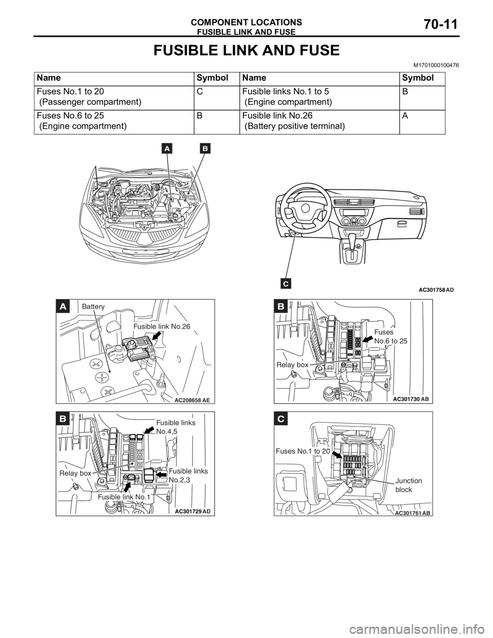
FUSIBLE LINK AND FUSE
M1701000100476
NameSymbolNameSymbol
Fuses No.1 to 20
(Passenger compartment)
CFusible links No.1 to 5
(Engine compartment)
B
Fuses No.6 to 25
(Engine compartment)
BFusible link No.26
(Battery positive terminal)
A
AC301758AD
AB
C
AC208658AE
A
Fusible link No.26
Battery
AC301729AD
B
Fusible link No.1
Relay box
Fusible links
No.4,5
Fusible links
No.2,3
AC301730
B
AB
Fuses
No.6 to 25
Relay box
AC301761
C
AB
Fuses No.1 to 20Junction
block
Page 407 of 800
AC300427
1
AD
AC301737AB
2 3
,
2
3
AC300429 AB
2
Junction
block
AC206768 AD
3
16
,
3
16
AC301742 AB
4
Glove box
AC301741AB
5
Diagnosis
connector
AC100195
6
AC
Windshield
wiper arm
AC212109AC
6Steering column
shaft assembly
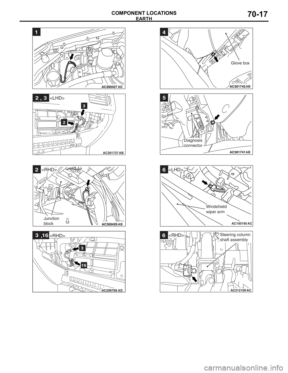
EARTH
COMPONENT LOCA
TIONS70-17
Page 409 of 800
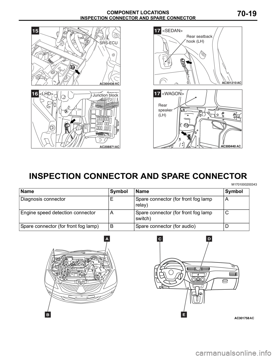
AC300436AC
15
SRS-ECU
AC208871AC
Junction block16
AC301210
17
AC
Rear seatback
hook (LH)
AC300440
17
AC
Rear
speaker
(LH)
INSPECTION CONN ECT O R AND SP ARE CONNEC T OR
COMPONENT LOCATIONS70-19
IN SPECTION CONNECT OR AND SP ARE CONNECT OR
M17010002 0034 3
NameSymbolNameSymbol
Diagnosis connectorESpare connector (for front fog lamp
relay)A
Engine speed detection connectorASpare connector (for front fog lamp
switch)C
Spare connector (for front fog lamp)BSpare connector (for audio)D
AC301758ACB
ADC
E
Page 441 of 800
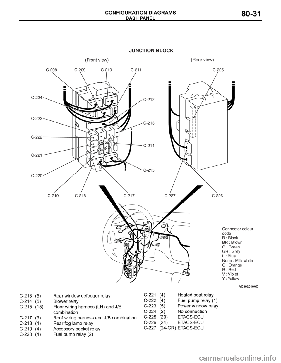
AC302010AC
(Front view)(Rear view)
C-208 C-209 C-210 C-211
C-212
C-213
C-214
C-215
C-217
C-218
C-219
C-220 C-221 C-222 C-223 C-224 C-225
C-226
C-227
JUNCTION BLOCK
Connector colour
code
B : Black
BR : Brown
G : Green
GR : Grey
L : Blue
None : Milk white
O : Orange
R : Red
V : Violet
Y : Yellow
C-213(5)Rear window defogger relay
C-214(5)Blower relay
C-215(15)Floor wiring harness (LH) and J/B
combination
C-217(3)Roof wiring harness and J/B combination
C-218(4)Rear fog lamp relay
C-219(4)Accessory socket relay
C-220(4)Fuel pump relay (2)
C-221(4)Heated seat relay
C-222(4)Fuel pump relay (1)
C-223(5)Power window relay
C-224(2)No connection
C-225(20)ETACS-ECU
C-226(24)ETACS-ECU
C-227(24-GR)ETACS-ECU
DASH P ANEL
CONF IGURA TION D I A G RA MS80-31