brake fluid MITSUBISHI LANCER IX 2006 Service Manual
[x] Cancel search | Manufacturer: MITSUBISHI, Model Year: 2006, Model line: LANCER IX, Model: MITSUBISHI LANCER IX 2006Pages: 800, PDF Size: 45.03 MB
Page 146 of 800
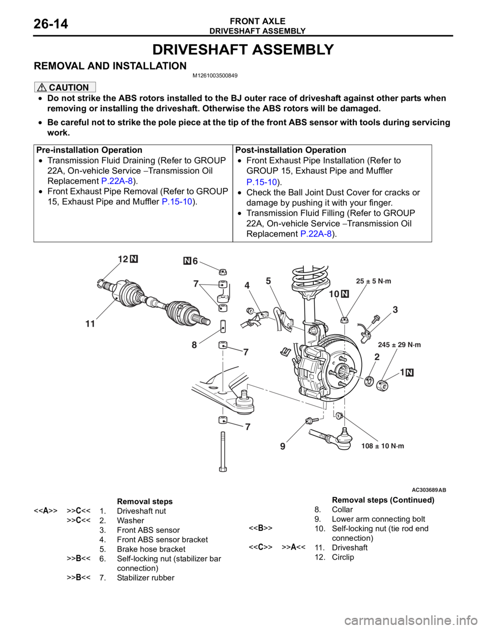
DRIVESHAFT ASSEMBLY
FRONT AXLE26-14
DRIVESHAFT ASSEMBLY
REMOVAL AND INSTALLATIONM1261003500849
CAUTION
•Do not strike the ABS rotors installed to the BJ outer race of driveshaft against other parts when
removing or installing the driveshaft. Otherwise the ABS rotors will be damaged.
•
Pre-installation Operation
•Transmission Fluid Draining (Refer to GROUP
22A, On-vehicle Service
− Transmission Oil
Replacement
P.22A-8).
•Front Exhaust Pipe Removal (Refer to GROUP
15, Exhaust Pipe and Muffler
P.15-10).
Post-installation Operation
•Front Exhaust Pipe Installation (Refer to
GROUP 15, Exhaust Pipe and Muffler
P.15-10).
•Check the Ball Joint Dust Cover for cracks or
damage by pushing it with your finger.
•Transmission Fluid Filling (Refer to GROUP
22A, On-vehicle Service
− Transmission Oil
Replacement
P.22A-8).
AC303689AB
9
N
N
NN
10
7
4
3
2 1
25 ± 5 N·m
245 ± 29 N·m
108 ± 10 N·m
8
5
6
11 12
77
Removal steps
<>>>C<<1.Driveshaft nut
>>C<<2.Washer
3.Front ABS sensor
4.Front ABS sensor bracket
5.Brake hose bracket
>>B<<6.Self-locking nut (stabilizer bar
connection)
>>B<<7.Stabilizer rubber
8.Collar
9.Lower arm connecting bolt
<>10.Self-locking nut (tie rod end
connection)
<
12.Circlip
Be careful not to strike the pole piece at the tip of the front ABS sensor with tools during servicing
work.
Removal steps (Continued)
Page 210 of 800
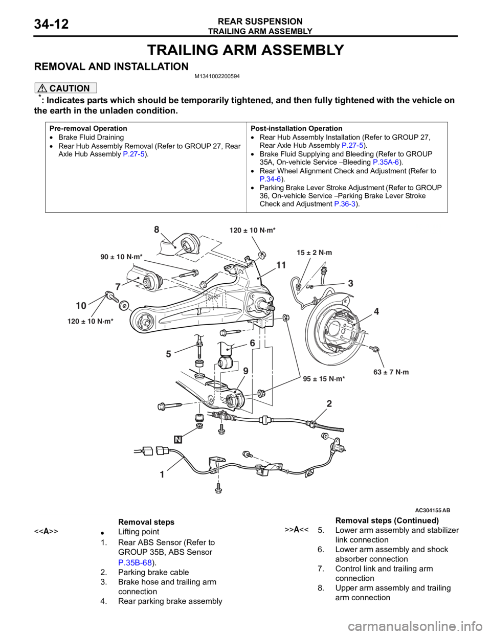
TRAILING ARM ASSEMBLY
REAR SUSPENSION34-12
TRAILING ARM ASSEMBLY
REMOVAL AND INSTALLATIONM1341002200594
CAUTION
*: Indicates parts which should be temporarily tightened, and then fully tightened with the vehicle on
the earth in the unladen condition.
Pre-removal Operation
•Brake Fluid Draining
•Rear Hub Assembly Removal (Refer to GROUP 27, Rear
Axle Hub Assembly P.27-5).
Post-installation Operation
•Rear Hub Assembly Installation (Refer to GROUP 27,
Rear Axle Hub Assembly
P.27-5).
•Brake Fluid Supplying and Bleeding (Refer to GROUP
35A, On-vehicle Service
− Bleeding P.35A-6).
•Rear Wheel Alignment Check and Adjustment (Refer to
P.34-6).
•Parking Brake Lever Stroke Ad justment (Refer to GROUP
36, On-vehicle Service
− Parking Brake Lever Stroke
Check and Adjustment
P.36-3).
AC101449
AC301223
AC304155 AB
90 ± 10 N·m*
120 ± 10 N·m* 95 ± 15 N·m*63 ± 7 N·m
6
7 8
1
10
11
23
4
120 ± 10 N·m*
15 ± 2 N·m
N
9
5
Removal steps
<>•Lifting point
1.Rear ABS Sensor (Refer to
GROUP 35B, ABS Sensor
P.35B-68).
2.Parking brake cable
3.Brake hose and trailing arm
connection
4.Rear parking brake assembly
>>A<<5.Lower arm assembly and stabilizer
link connection
6.Lower arm assembly and shock
absorber connection
7.Control link and trailing arm
connection
8.Upper arm assembly and trailing
arm connection
Removal steps (Continued)
Page 420 of 800
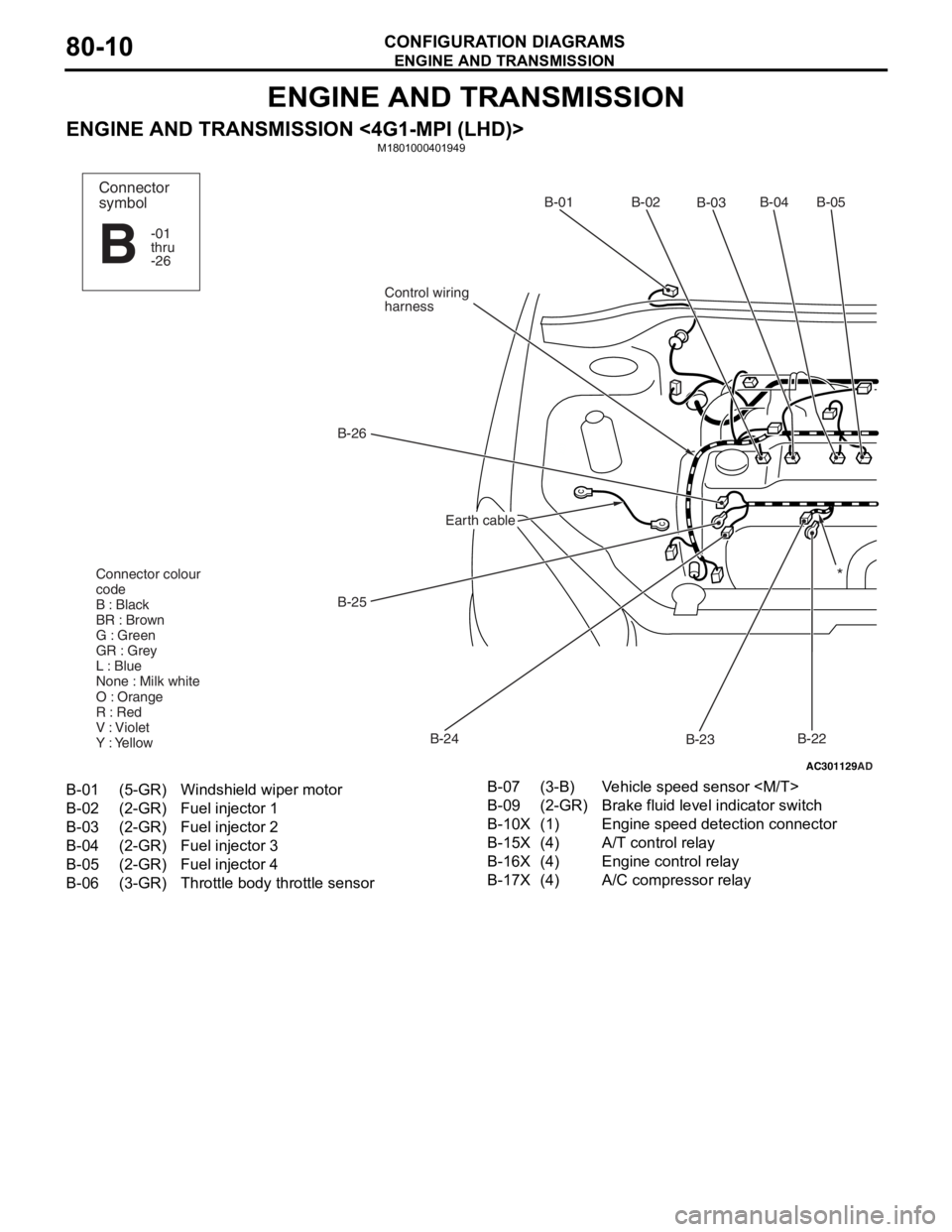
ENGINE AND TRANSMISSION
CONFIGURATION DIAGRAMS80-10
ENGINE AND TRANSMISSION
ENGINE AND TRANSMISSION <4G1-MPI (LHD)>M1801000401949
AC301129
AD
B-02
B-03B-04B-05
B-22
B-23
B-24
B-25
B-26
Control wiring
harnessB-01
Connector colour
code
B : Black
BR : Brown
G : Green
GR : Grey
L : Blue
None : Milk white
O : Orange
R : Red
V : Violet
Y : Yellow*
Connector
symbol
-01
thru
-26
B
Earth cable
B-01(5-GR)Windshield wiper motor
B-02(2-GR)Fuel injector 1
B-03(2-GR)Fuel injector 2
B-04(2-GR)Fuel injector 3
B-05(2-GR)Fuel injector 4
B-06(3-GR)Throttle body throttle sensor
B-07(3-B)Vehicle speed sensor
B-09(2-GR)Brake fluid level indicator switch
B-10X(1)Engine speed detection connector
B-15X(4)A/T control relay
B-16X(4)Engine control relay
B-17X(4)A/C compressor relay
Page 424 of 800
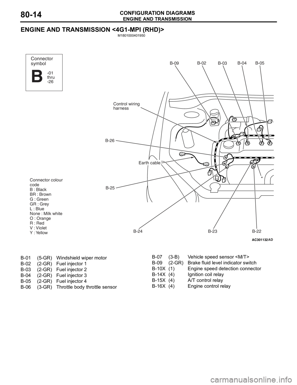
ENGINE AND TRANSMISSION
CONFIGURATION DIAGRAMS80-14
ENGINE AND TRANSMISSION <4G1-MPI (RHD)>
M1801000401950
AC301132AD
B-02
B-03B-04 B-05
B-22
B-23
B-24
B-25
B-26
Control wiring
harnessB-09
Connector colour
code
B : Black
BR : Brown
G : Green
GR : Grey
L : Blue
None : Milk white
O : Orange
R : Red
V : Violet
Y : Yellow*
Connector
symbol
-01
thru
-26
B
Earth cable
B-01(5-GR)Windshield wiper motor
B-02(2-GR)Fuel injector 1
B-03(2-GR)Fuel injector 2
B-04(2-GR)Fuel injector 3
B-05(2-GR)Fuel injector 4
B-06(3-GR)Throttle body throttle sensor
B-07(3-B)Vehicle speed sensor
B-09(2-GR)Brake fluid level indicator switch
B-10X(1)Engine speed detection connector
B-14X(4)Ignition coil relay
B-15X(4)A/T control relay
B-16X(4)Engine control relay
Page 428 of 800
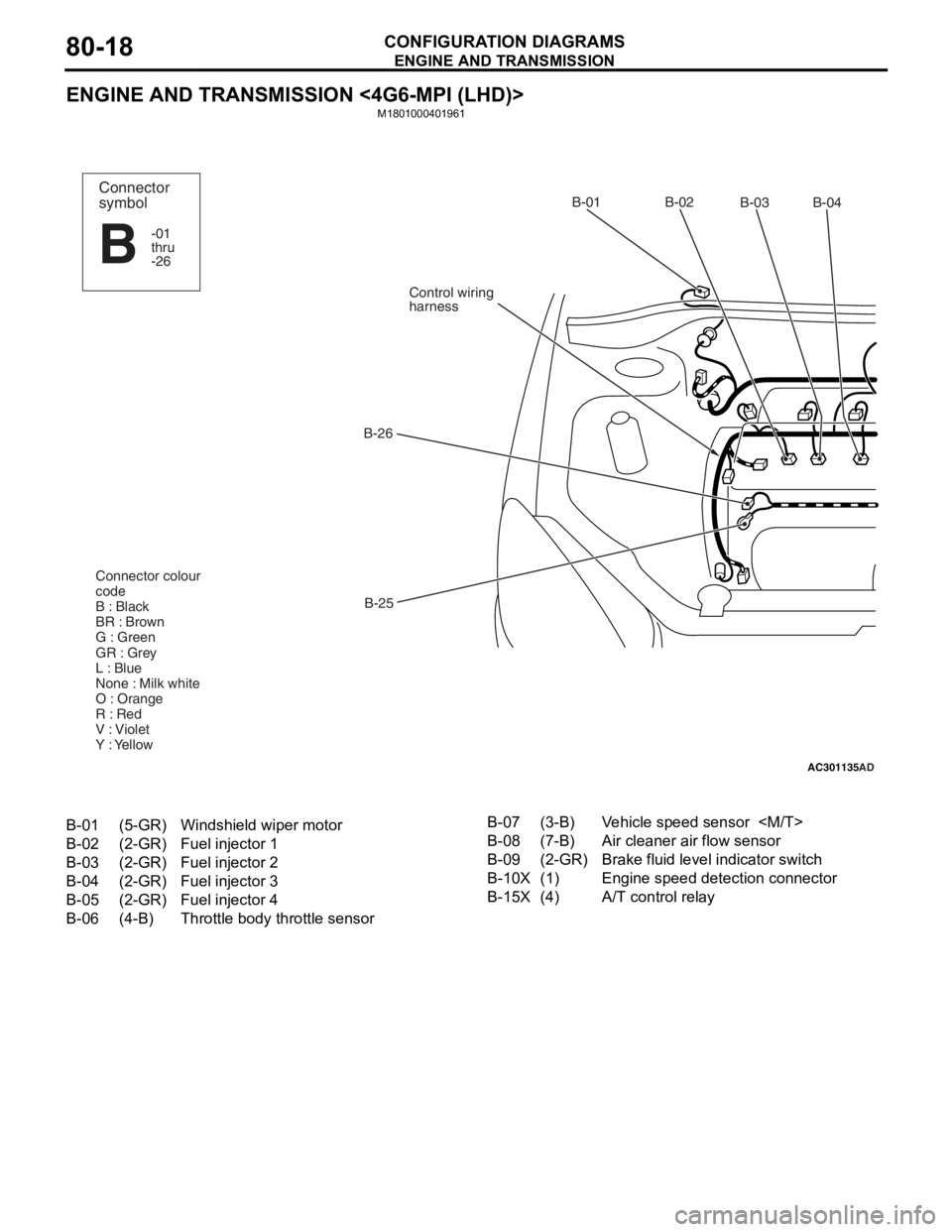
ENGINE AND TRANSMISSION
CONFIGURATION DIAGRAMS80-18
ENGINE AND TRANSMISSION <4G6-MPI (LHD)>
M1801000401961
AC301135AD
B-02
B-03B-04
B-25
B-26
Control wiring
harnessB-01
Connector colour
code
B : Black
BR : Brown
G : Green
GR : Grey
L : Blue
None : Milk white
O : Orange
R : Red
V : Violet
Y : YellowConnector
symbol
-01
thru
-26
B
B-01(5-GR)Windshield wiper motor
B-02(2-GR)Fuel injector 1
B-03(2-GR)Fuel injector 2
B-04(2-GR)Fuel injector 3
B-05(2-GR)Fuel injector 4
B-06(4-B)Throttle body throttle sensor
B-07(3-B)Vehicle speed sensor
B-08(7-B)Air cleaner air flow sensor
B-09(2-GR)Brake fluid level indicator switch
B-10X(1)Engine speed detection connector
B-15X(4)A/T control relay
Page 432 of 800
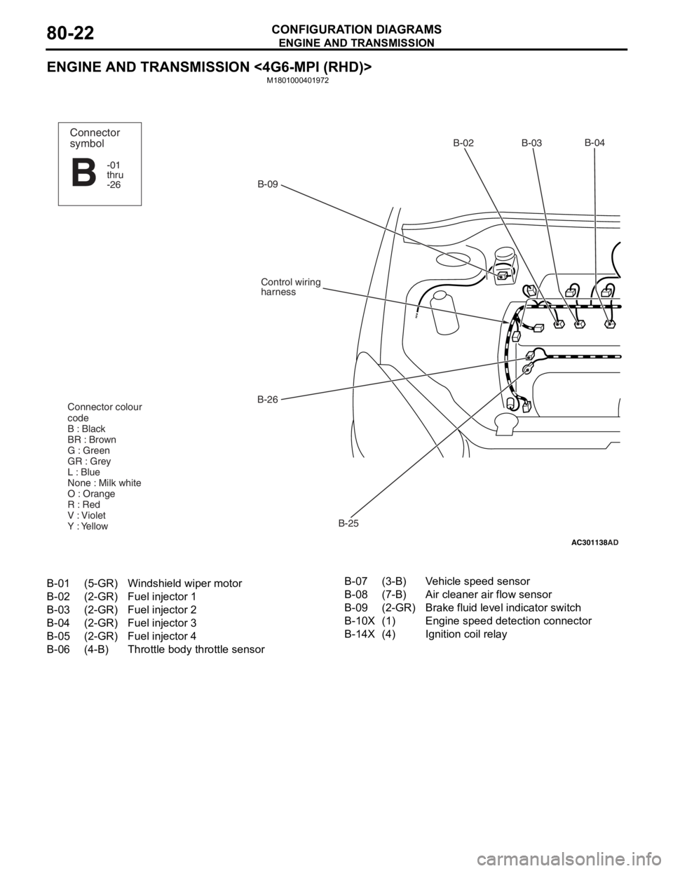
ENGINE AND TRANSMISSION
CONFIGURATION DIAGRAMS80-22
ENGINE AND TRANSMISSION <4G6-MPI (RHD)>
M1801000401972
AC301138
AD
B-02 B-03B-04
B-25
B-26
Control wiring
harness
B-09
Connector colour
code
B : Black
BR : Brown
G : Green
GR : Grey
L : Blue
None : Milk white
O : Orange
R : Red
V : Violet
Y : Yellow
Connector
symbol
-01
thru
-26
B
B-01(5-GR)Windshield wiper motor
B-02(2-GR)Fuel injector 1
B-03(2-GR)Fuel injector 2
B-04(2-GR)Fuel injector 3
B-05(2-GR)Fuel injector 4
B-06(4-B)Throttle body throttle sensor
B-07(3-B)Vehicle speed sensor
B-08(7-B)Air cleaner air flow sensor
B-09(2-GR)Brake fluid level indicator switch
B-10X(1)Engine speed detection connector
B-14X(4)Ignition coil relay
Page 661 of 800
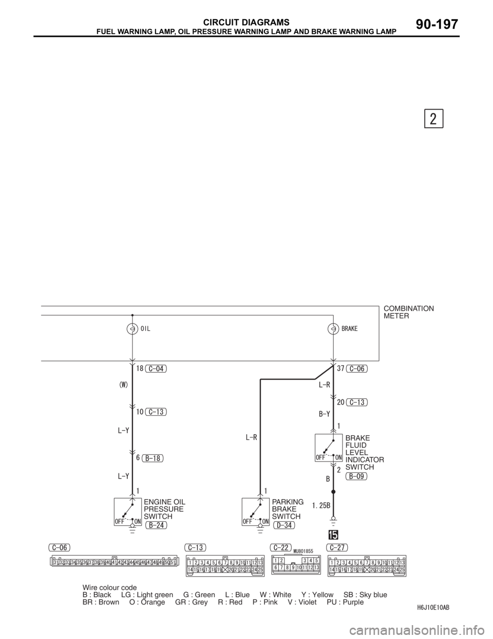
FUEL WARNING LAMP, OIL PRESSURE WARNING LAMP AND BRAKE WARNING LAMP
CIRCUIT DIAGRAMS90-197
COMBINATION
METER
BRAKE
FLUID
LEVEL
INDICATOR
SWITCH
ENGINE OIL
PRESSURE
SWITCHPARKING
BRAKE
SWITCH
Wire colour code
B : Black LG : Light green G : Green L : Blue W : White Y : Yellow SB : Sky blue
BR : Brown O : Orange GR : Grey R : Red P : Pink V : Violet PU : Purple
Page 663 of 800
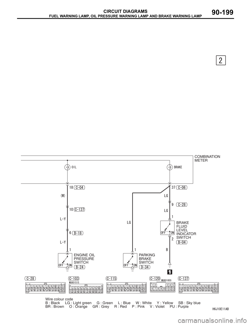
FUEL WARNING LAMP, OIL PRESSURE WARNING LAMP AND BRAKE WARNING LAMP
CIRCUIT DIAGRAMS90-199
COMBINATION
METER
BRAKE
FLUID
LEVEL
INDICATOR
SWITCH
ENGINE OIL
PRESSURE
SWITCHPARKING
BRAKE
SWITCH
Wire colour code
B : Black LG : Light green G : Green L : Blue W : White Y : Yellow SB : Sky blue
BR : Brown O : Orange GR : Grey R : Red P : Pink V : Violet PU : Purple