check oil MITSUBISHI LANCER IX 2006 Service Manual
[x] Cancel search | Manufacturer: MITSUBISHI, Model Year: 2006, Model line: LANCER IX, Model: MITSUBISHI LANCER IX 2006Pages: 800, PDF Size: 45.03 MB
Page 7 of 800
12-1
GROUP 12
ENGINE
LUBRIC ATION
CONTENTS
GENERAL INFORMATIO N . . . . . . . .12-2
SERVICE SPECIFICATION . . . . . . . .12-2
LUBRICANT . . . . . . . . . . . . . . . . . . . .12-2
SEALANT . . . . . . . . . . . . . . . . . . . . . .12-3
SPECIAL TOOLS . . . . . . . . . . . . . . . .12-3
ON-VEHICLE SERVICE . . . . . . . . . . .12-4
ENGINE OIL CHECK . . . . . . . . . . . . . . . . . 12-4
ENGINE OIL REPLACEMENT . . . . . . . . . . 12-4
ENGINE OIL FILTER REPLACEMENT . . . . 12-4
OIL PRESSURE CHECK . . . . . . . . . . . . . . 12-5
Page 10 of 800
ON-VEHICLE SERVICE
ENGINE LUBRICATION12-4
ON-VEHICLE SERVICE
ENGINE OIL CHECKM1121000900342
ACX00892 AC
Good
Maximum Minimum
<4G1>
AC205268
Maximum MinimumGood
AC
<4G6>
1.
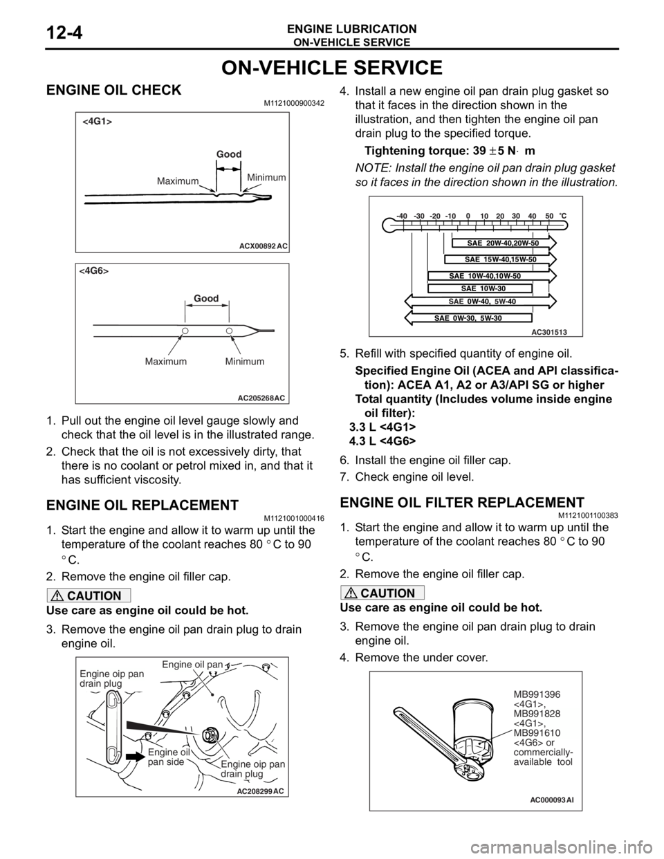
Pull ou t the en gine oil level ga uge slowly and
check tha t the o il level is in t he illustrated range.
2.Check t hat the oil is not excessively dirty , that
th ere is no coolant or p e trol mixed in, and that it
ha s s u f f i c ie nt vi sc osi t y .
ENGINE OIL REPLACEMENT
M1121 0010 0041 6
1.S t art the engin e and allow it to war m up until the
te mpera t ure of the coola n t reaches 80
°C to 90
°C.
2.Remove the en gine oil filler ca p.
CAUTION
Use care as engine oil could be hot.
3. Remove the engine oil pan drain plug to drain
engine oil.
AC208299
Engine oil pan
AC
Engine oip pan
drain plug
Engine oip pan
drain plug
Engine oil
pan side
4. Install a new engine oil pan drain plug gasket so
that it faces in the direction shown in the
illustration, and then tighten the engine oil pan
drain plug to the specified torque.
Tightening torque: 39 ± 5 N⋅m
NOTE: Install the engine oil pan drain plug gasket
so it faces in the direction shown in the illustration.
AC301513
5. Refill with specifi ed quantity of engine oil.
Specified Engine Oil (ACEA and API classifica-
tion): ACEA A1, A2 or A3/API SG or higher
Total quantity (Includes volume inside engine
oil filter):
3.3 L <4G1>
4.3 L <4G6>
6. Install the engine oil filler cap.
7. Check engine oil level.
ENGINE OIL FILTER REPLACEMENTM1121001100383
1. Start the engine and allow it to warm up until the temperature of the coolant reaches 80
°C to 90
°C.
2. Remove the engine oil filler cap.
CAUTION
Use care as engine oil could be hot.
3. Remove the engine oil pan drain plug to drain engine oil.
4. Remove the under cover.
AC000093
MB991396
<4G1>,
MB991828
<4G1>,
MB991610
<4G6> or
commercially-
available tool
AI
Page 11 of 800
ON-VEHICLE SERVICE
ENGINE LUBRICATION12-5
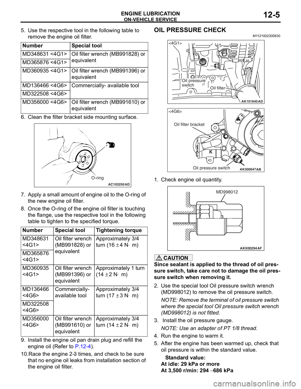
5. Use the respective tool in the following table to remove the engine oil filter.
NumberSpecial tool
MD348631 <4G1>Oil filter wrench (MB991828) or
equivalent
MD365876 <4G1>
MD360935 <4G1>Oil filter wrench (MB991396) or
equivalent
MD136466 <4G6>Commercially- available tool
MD322508 <4G6>
MD356000 <4G6>Oil filter wrench (MB991610) or
equivalent
6. Cle an the filt er bracket side mou n ting surfa c e.
AC103250AD
O-ring
7.Ap ply a small a m ou nt o f en gine o i l to th e O-rin g of
th e new eng ine oil f ilte r .
8.Once the O-ring of the engine oil filter is tou c hing
th e flange, use the resp ective tool in the following
t able to tighten to the specified tor que.
NumberSpecial toolTightening torque
MD348631
<4G1>Oil filter wrench
(MB991828) or
equivalentApproximately 3/4
turn (16
± 4 N⋅m)
MD365876
<4G1>
MD360935
<4G1>Oil filter wrench
(MB991396) or
equivalentApproximately 1 turn
(14
± 2 N⋅m)
MD136466
<4G6>Commercially-
available toolApproximately 3/4
turn (17
± 3 N⋅m)
MD322508
<4G6>
MD356000
<4G6>Oil filter wrench
(MB991610) or
equivalentApproximately 3/4
turn (14
± 2 N⋅m)
9.In st all the en gine oil p a n drain plu g and refill the
en gine oil (Re f er to
P.12-4).
10.Race the en gine 2−3 times, and che ck to be sure
th
at n
o
en
gin
e
oil leaks fr om in st allation sectio n of
th
e engine oil filter
.
OIL PRESSURE CHECK
M1 121 0023 0083 0
AK101640
<4G1>
Oil pressure
switch
Oil filter
AD
AK300647
AB
<4G6>
Oil filter bracket
Oil pressure switch
1.Check e ngin e oil quan tity .
AKX00294
MD998012
AF
CAUTION
Since sealant is applied to the thread of oil pres-
sure switch, take care not to damage the oil pres-
sure switch when removing it.
2. Use the special tool Oil pressure switch wrench
(MD998012) to remove the oil pressure switch.
NOTE: Remove the terminal of oil pressure switch
where the special tool Oil pressure switch wrench
(MD998012) is not fitted.
3. Install the oil pressure gauge.
NOTE: Use an adapter of PT 1/8 thread.
4. Run the engine to warm it.
5. After the engine has been warmed up, check that oil pressure is within the standard value.
Standard value:
At idle: 29 kPa or more
At 3,500 r/min: 294 − 686 kPa
Page 46 of 800
Page 56 of 800
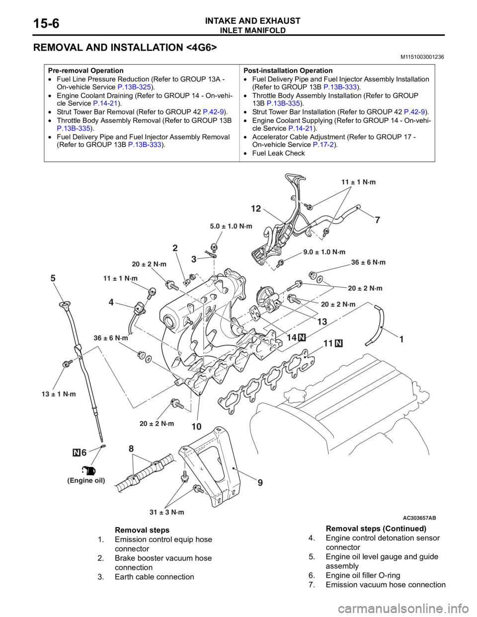
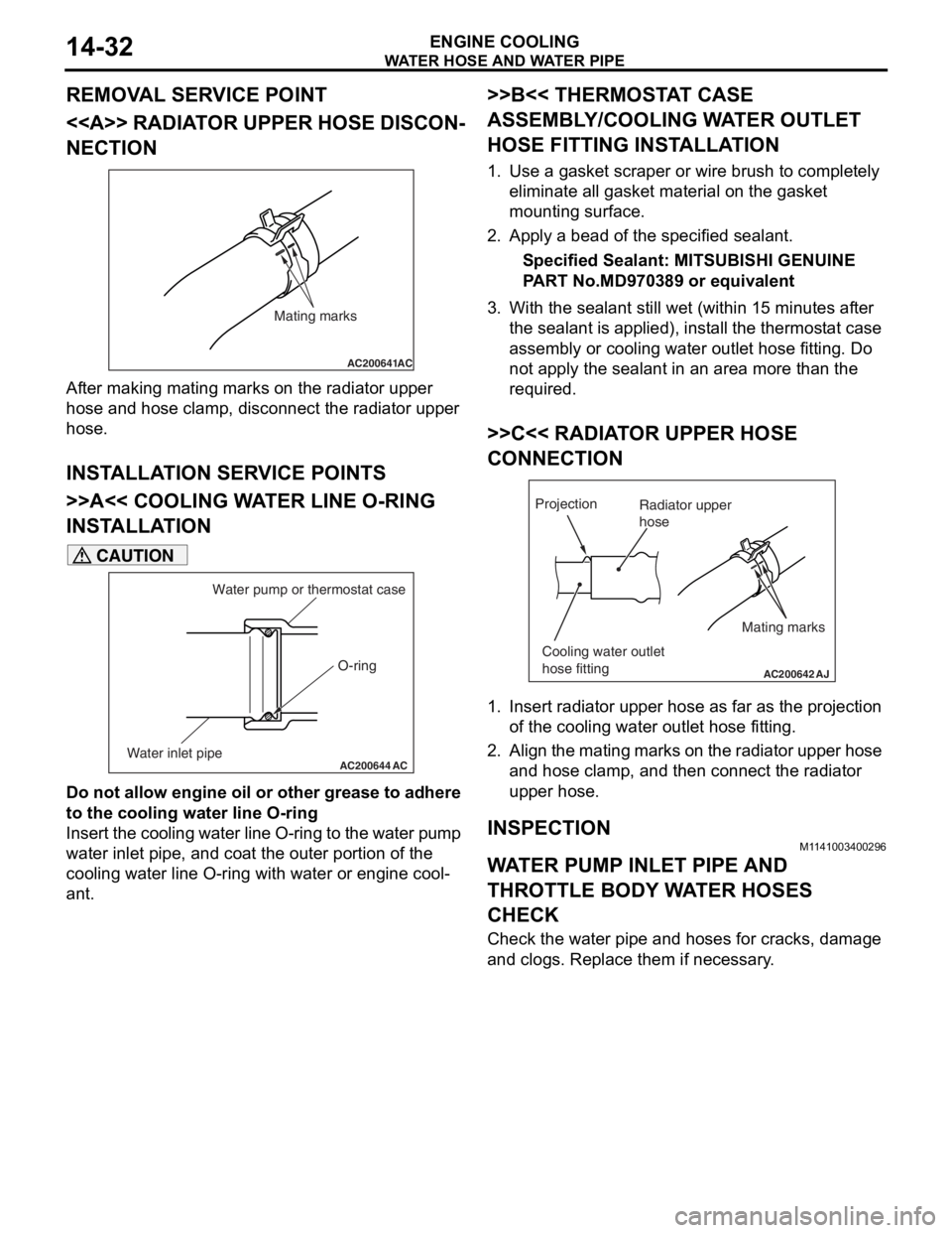
INLET MANIFOLD
INTAKE AND EXHAUST15-6
REMOVAL AND INSTALLATION <4G6>
M1151003001236
Pre-removal Operation
•Fuel Line Pressure Reduction (Refer to GROUP 13A -
On-vehicle Service P.13B-325).
•Engine Coolant Draining (Refer to GROUP 14 - On-vehi-cle Service P.14-21).
•Strut Tower Bar Removal (Refer to GROUP 42 P.42-9).
•Throttle Body Assembly Re moval (Refer to GROUP 13B
P.13B-335).
•Fuel Delivery Pipe and Fuel Injector Assembly Removal
(Refer to GROUP 13B
P.13B-333).
Post-installation Operation
•Fuel Delivery Pipe and Fuel Injector Assembly Installation
(Refer to GROUP 13B P.13B-333).
•Throttle Body Assembly Inst allation (Refer to GROUP
13B P.13B-335).
•Strut Tower Bar Installati on (Refer to GROUP 42 P.42-9).
•Engine Coolant Supplying (Refer to GROUP 14 - On-vehi-
cle Service P.14-21).
•Accelerator Cable Adjustment (Refer to GROUP 17 -
On-vehicle Service
P.17-2).
•Fuel Leak Check
AC303657
9.0 ± 1.0 N·m11 ± 1 N·m
20 ± 2 N·m 31 ± 3 N·m
36 ± 6 N·m
20 ± 2 N·m
20 ± 2 N·m
36 ± 6 N·m
20 ± 2 N·m
11
9
10
2
12
N14
13N
AB
5.0 ± 1.0 N·m
3
1
11 ± 1 N·m
4
N
13 ± 1 N·m
5
6
(Engine oil)
7
8
Removal steps
1.Emission control equip hose
connector
2.Brake booster vacuum hose
connection
3.Earth cable connection
4.Engine control detonation sensor
connector
5.Engine oil level gauge and guide
assembly
6.Engine oil filler O-ring
7.Emission vacuum hose connection
Removal steps (Continued)
Page 57 of 800
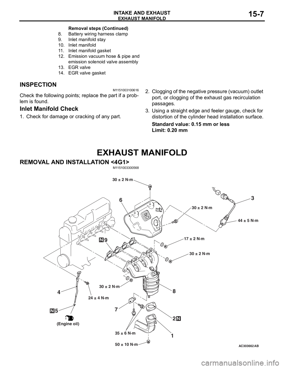
EXHAUST MANIFOLD
INTAKE AND EXHAUST15-7
INSPECTION
M1151003100616
Check the following points; replace the part if a prob-
lem is found.
Inlet Manifold Check
1. Check for damage or cracking of any part.
2. Clogging of the negative pressure (vacuum) outlet port, or clogging of the exhaust gas recirculation
passages.
3. Using a straight edge and feeler gauge, check for distortion of the cylinder head installation surface.
Standard value: 0.15 mm or less
Limit: 0.20 mm
EXHAUST MANIFOLD
REMOVAL AND INSTALLATION <4G1>
M1151003300568
AC30366250 ± 10 N·m
24 ± 4 N·m
35 ± 6 N·m 17 ± 2 N·m
30 ± 2 N·m
N
3
7 12
4
N
6
8
44 ± 5 N·m
AB
9
5N
30 ± 2 N·m
30 ± 2 N·m
30 ± 2 N·m
(Engine oil)
8.Battery wirin g ha rne s s clamp
9.Inlet manifold st ay
10.Inlet manifold
11.Inlet manifold gask et
12.Emission vacuu m hose & pipe and
emis
sion s o lenoid valve assembly
13.EGR v a lve
14.EGR v a lve gasket
Remo va l st ep s ( C o n t in u e d)
Page 63 of 800
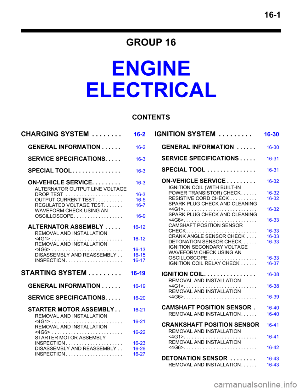
16-1
GROUP 16
ENGINE
ELECTRICAL
CONTENTS
CHARGING SYSTEM . . . . . . . .16-2
GENERAL INFORMATION . . . . . .16-2
SERVICE SPECIFICATIONS. . . . .16-3
SPECIAL TOOL . . . . . . . . . . . . . . .16-3
ON-VEHICLE SERVICE. . . . . . . . .16-3
ALTERNATOR OUTPUT LINE VOLTAGE
DROP TEST . . . . . . . . . . . . . . . . . . . . . 16-3
OUTPUT CURRENT TEST . . . . . . . . . . 16-5
REGULATED VOLTAGE TEST . . . . . . . 16-7
WAVEFORM CHECK USING AN
OSCILLOSCOPE . . . . . . . . . . . . . . . . . . 16-9
ALTERNATOR ASSEMB LY . . . . .16-12
REMOVAL AND INSTALLATION
<4G1> . . . . . . . . . . . . . . . . . . . . . . . . . . 16-12
REMOVAL AND INSTALLATION
<4G6> . . . . . . . . . . . . . . . . . . . . . . . . . . 16-13
DISASSEMBLY AND REASSEMBLY . . 16-15
INSPECTION . . . . . . . . . . . . . . . . . . . . . 16-17
STARTING SYSTEM . . . . . . . . .16-19
GENERAL INFORMATION . . . . . .16-19
SERVICE SPECIFICATIONS. . . . .16-20
STARTER MOTOR ASSEMBLY . .16-21
REMOVAL AND INSTALLATION
<4G1> . . . . . . . . . . . . . . . . . . . . . . . . . . 16-21
REMOVAL AND INSTALLATION
<4G6> . . . . . . . . . . . . . . . . . . . . . . . . . . 16-22
STARTER MOTOR ASSEMBLY
INSPECTION . . . . . . . . . . . . . . . . . . . . . 16-23
DISASSEMBLY AND REASSEMBLY . . 16-26
INSPECTION . . . . . . . . . . . . . . . . . . . . . 16-27
IGNITION SYSTEM . . . . . . . . . 16-30
GENERAL INFORMATION . . . . . .16-30
SERVICE SPECIFICATIONS . . . . .16-31
SPECIAL TOOL . . . . . . . . . . . . . . .16-31
ON-VEHICLE SERVICE . . . . . . . . .16-32
IGNITION COIL (WITH BUILT-IN
POWER TRANSISTOR) CHECK . . . . . . 16-32
RESISTIVE CORD CHECK . . . . . . . . . . 16-32
SPARK PLUG CHECK AND CLEANING
<4G1>. . . . . . . . . . . . . . . . . . . . . . . . . . . 16-32
SPARK PLUG CHECK AND CLEANING
<4G6>. . . . . . . . . . . . . . . . . . . . . . . . . . . 16-33
CAMSHAFT POSITION SENSOR
CHECK . . . . . . . . . . . . . . . . . . . . . . . . . . 16-33
CRANK ANGLE SENSOR CHECK . . . . 16-33
DETONATION SENSOR CHECK . . . . . 16-33
IGNITION SECONDARY VOLTAGE
WAVEFORM CHECK USING AN
OSCILLOSCOPE . . . . . . . . . . . . . . . . . . 16-33
IGNITION COIL RELAY CHECK . . . . . . 16-37
IGNITION COIL . . . . . . . . . . . . . . . .16-38
REMOVAL AND INSTALLATION
<4G1>. . . . . . . . . . . . . . . . . . . . . . . . . . . 16-38
REMOVAL AND INSTALLATION
<4G6>. . . . . . . . . . . . . . . . . . . . . . . . . . . 16-39
CAMSHAFT POSITION SENSOR .16-40
REMOVAL AND INSTALLATION . . . . . . 16-40
CRANKSHAFT POSITION SENSOR16-41
REMOVAL AND INSTALLATION
<4G1>. . . . . . . . . . . . . . . . . . . . . . . . . . . 16-41
REMOVAL AND INSTALLATION
<4G6>. . . . . . . . . . . . . . . . . . . . . . . . . . . 16-42
DETONATION SENSOR . . . . . . . .16-43
REMOVAL AND INSTALLATION . . . . . . 16-43
Page 79 of 800

CHARGING SYSTEM
ENGINE ELECTRICAL16-17
>>B<< ROTOR INSTALLATION
AK202779
Wire
AB
Remove the br ush holding wire af ter the rotor ha s
been inst
alled.
INSPECTION
M1161 0017 0015 2
ROTO R
AK202735
1. Measure th e resist a n ce b e tween the two slip rings
of the rot o r coil to check t he co ntinu i ty between
th em.
Repla c e th e r o to r if th e resist ance is no t within the
st
a ndard valu e range .
St andard va lue: 3 − 5 Ω
2.Check t he co ntinu i ty between the slip rings and
core.
AK202736
3. If cont inuity is pre s ent, repla c e th e rotor .
STA T OR
AK202716
1.Check t he co ntinu i ty between coil le ads.
If there is no con t inuity , replace the st a t or .
AK202717
2.Check t he co ntinu i ty between coil and core .
If there is no con t inuity , replace the st a t or .
RECTIFIER ASSEBMLY
AK202803
1.Check t he co ndition o f the (+) h eat sink by
checkin g contin uity be twe en t he (+) heat sink and
e a ch o f the st a t or coil lead conn ecting termina l s.
If cont inuity is pre s ent for both terminals, the
d
i ode is shorte d. Repla c e th e rectifie r assembly .
Page 85 of 800
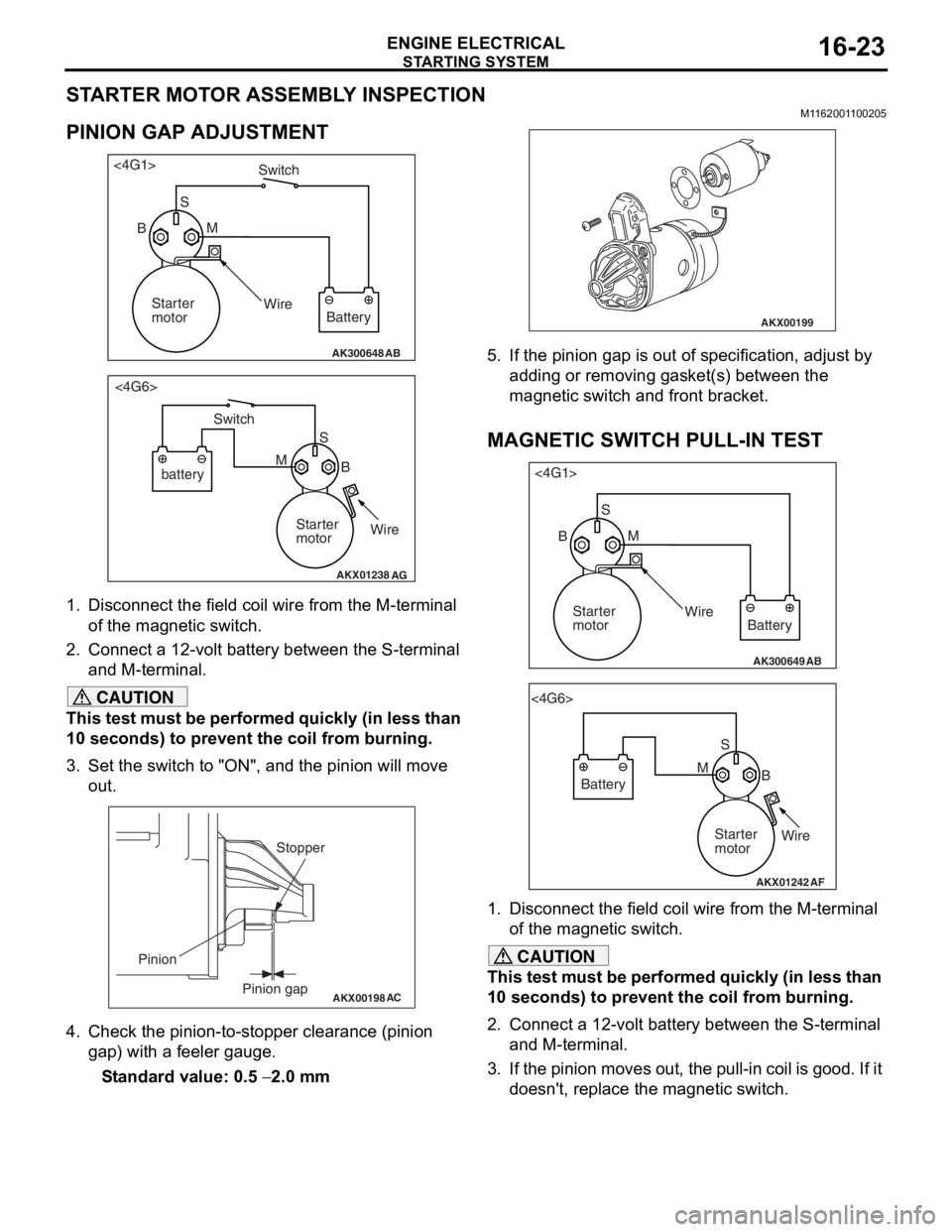
STARTING SYSTEM
ENGINE ELECTRICAL16-23
STARTER MOTOR ASSEMBLY INSPECTION
M1162001100205
PINION GAP ADJUSTMENT
AK300648AB
<4G1>
Switch
S M
Wire Battery
Starter
motor
B
AKX01238
<4G6>
B
M S
battery Switch
Starter
motorWire
AG
1.
Disco nnect the field coil wire f r om th e M-te rmin al
of the magnet ic switch.
2.Conn ect a 12-volt b a ttery between the S-termina l
an d M-t e rminal.
CAUTION
This test must be performed quickly (in less than
10 seconds) to prevent the coil from burning.
3. Set the switch to "ON", and the pinion will move out.
AKX00198
Stopper
Pinion gap
Pinion
AC
4. Check the pinion-to-stopper clearance (pinion
gap) with a feeler gauge.
Standard value: 0.5 − 2.0 mm
AKX00199
5. If the pinion gap is out of specification, adjust by adding or removing gasket(s) between the
magnetic switch and front bracket.
MAGNETIC SWITCH PULL-IN TEST
AK300649AB
<4G1>
SM
Wire Battery
Starter
motor
B
AKX01242
<4G6>
SB
M
Battery
Starter
motorWire
AF
1. Disconnect the field coil wire from the M-terminal
of the magnetic switch.
CAUTION
This test must be performed quickly (in less than
10 seconds) to prevent the coil from burning.
2. Connect a 12-volt battery between the S-terminal and M-terminal.
3. If the pinion moves out, the pull-in coil is good. If it doesn't, replace the magnetic switch.
Page 90 of 800
AK202711
SegmentUndercut
Mica
AB
ST ARTING SYS TEM
ENGINE ELECTRICAL16-28
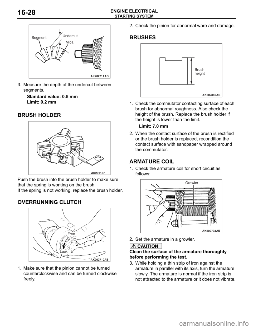
3.Measure the depth of the undercut be twe en
segment s.
St andard va lue: 0.5 mm
Limit: 0.2 mm
BRUSH HOLDER
AK201187
Push th e brush in to the b r ush hold e r to make sure
that the
spring is working o n the b r ush.
If the spring is not working, repla c e th e brush holder .
OVERRUNNING CLUTCH
AK202710
Free
Lock
AB
1.Make sure that th e pin i on canno t be tu rned
counte r clo ckwise a nd ca n be tu rned clockwise
fre e ly .
2.Check t he pinion for abn ormal ware an d damage.
BRUSHES
AK202846
Brush
height
AB
1.Che ck the commut ator con t a c tin g surface of each
b r ush f o r abno rmal rough ness. Also ch eck the
h e ight of the brush . Replace th e brush holder if
th e height is lo we r than t he limit.
Limit: 7.0 mm
2.Wh en the con t act su rface of the brush is rectified
o r the bru s h h o lder is re placed, re cond itio n the
cont act surfa c e wit h san d p a p e r wrapped around
th e co mmu t a t o r .
ARMATURE COIL
1.Check t he armature coil for short circuit a s
fo llows:
AK202733
Growler
AB
2.Set the armature in a growler .
CAUTION
Clean the surface of the armature thoroughly
before performing the test.
3. While holding a thin strip of iron against the
armature in parallel with it s axis, turn the armature
slowly. The armature is normal if the iron strip is
not attracted to the armature or it does not vibrate.