stop start MITSUBISHI LANCER IX 2006 Service Manual
[x] Cancel search | Manufacturer: MITSUBISHI, Model Year: 2006, Model line: LANCER IX, Model: MITSUBISHI LANCER IX 2006Pages: 800, PDF Size: 45.03 MB
Page 36 of 800
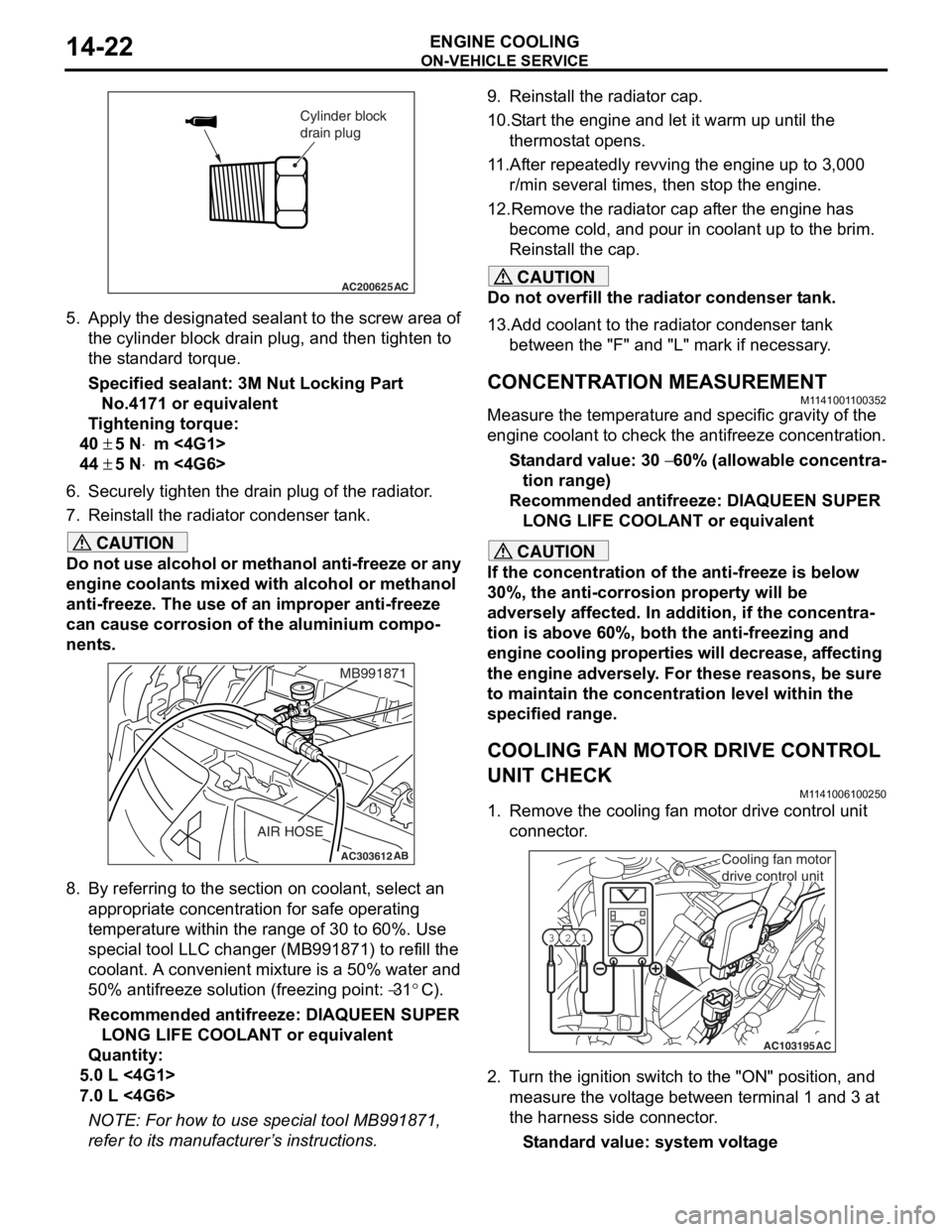
AC200625
Cylinder block
drain plug
AC
ON-VEHICLE SER VICE
ENGINE COOLING14-22
5.App l y the designa ted sealant to t he scre w area of
th e cylin der block drain plu g , and then tighten to
th e st and ard torq ue.
Sp e c ified s ealant: 3 M Nut Loc king Part
No. 4171 o r e quivale n t
Ti ghtenin g torque:
40 ± 5 N⋅m <4G1>
44 ± 5 N⋅m <4G6>
6.Securely tighten t he drain plug of t he radiator .
7.Reinst all the ra diato r con denser t ank.
CAUTION
Do not use alcohol or methanol anti-freeze or any
engine coolants mixed with alcohol or methanol
anti-freeze. The use of an improper anti-freeze
can cause corrosion of the aluminium compo
-
nents.
AC303612AB
MB991871
AIR HOSE
8. By referring to the section on coolant, select an
appropriate concentration for safe operating
temperature within the range of 30 to 60%. Use
special tool LLC changer (MB991871) to refill the
coolant. A convenient mixture is a 50% water and
50% antifreeze solution (freezing point:
−31°C).
Recommended antifreeze: DIAQUEEN SUPER LONG LIFE COOLANT or equivalent
Quantity:
5.0 L <4G1>
7.0 L <4G6>
NOTE: For how to use special tool MB991871,
refer to its manufacturer’s instructions.
9. Reinstall the radiator cap.
10.Start the engine and let it warm up until the thermostat opens.
11.After repeatedly revving the engine up to 3,000 r/min several times, then stop the engine.
12.Remove the radiator cap after the engine has become cold, and pour in coolant up to the brim.
Reinstall the cap.
CAUTION
Do not overfill the radiator condenser tank.
13.Add coolant to the radiator condenser tank between the "F" and "L" mark if necessary.
CONCENTRATION MEASUREMENT
M1141001100352
Measure the temperature and specific gravity of the
engine coolant to check the antifreeze concentration.
Standard value: 30 − 60% (allowable concentra-
tion range)
Recommended antifreeze: DIAQUEEN SUPER
LONG LIFE COOLANT or equivalent
CAUTION
If the concentration of the anti-freeze is below
30%, the anti-corrosion property will be
adversely affected. In addition, if the concentra
-
tion is above 60%, both the anti-freezing and
engine cooling properties will decrease, affecting
the engine adversely. For these reasons, be sure
to maintain the concentration level within the
specified range.
COOLING FAN MOTOR DRIVE CONTROL
UNIT CHECK
M1141006100250
1. Remove the cooling fan motor drive control unit connector.
AC103195
Y1716AU
1
23
AC
Cooling fan motor
drive control unit
2. Turn the ignition switch to the "ON" position, and
measure the voltage between terminal 1 and 3 at
the harness side connector.
Standard value: system voltage
Page 85 of 800
STARTING SYSTEM
ENGINE ELECTRICAL16-23
STARTER MOTOR ASSEMBLY INSPECTION
M1162001100205
PINION GAP ADJUSTMENT
AK300648AB
<4G1>
Switch
S M
Wire Battery
Starter
motor
B
AKX01238
<4G6>
B
M S
battery Switch
Starter
motorWire
AG
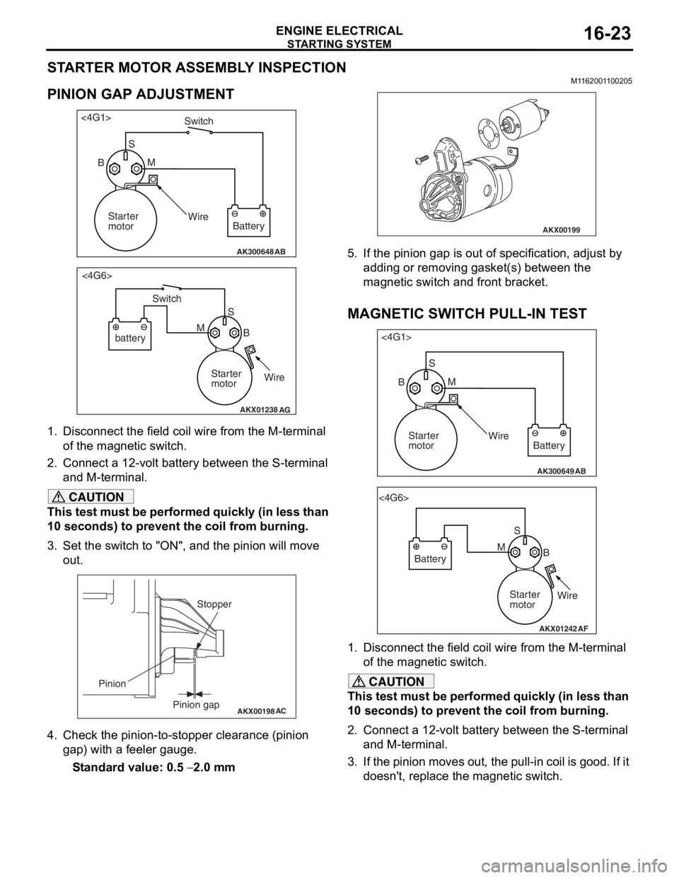
1.
Disco nnect the field coil wire f r om th e M-te rmin al
of the magnet ic switch.
2.Conn ect a 12-volt b a ttery between the S-termina l
an d M-t e rminal.
CAUTION
This test must be performed quickly (in less than
10 seconds) to prevent the coil from burning.
3. Set the switch to "ON", and the pinion will move out.
AKX00198
Stopper
Pinion gap
Pinion
AC
4. Check the pinion-to-stopper clearance (pinion
gap) with a feeler gauge.
Standard value: 0.5 − 2.0 mm
AKX00199
5. If the pinion gap is out of specification, adjust by adding or removing gasket(s) between the
magnetic switch and front bracket.
MAGNETIC SWITCH PULL-IN TEST
AK300649AB
<4G1>
SM
Wire Battery
Starter
motor
B
AKX01242
<4G6>
SB
M
Battery
Starter
motorWire
AF
1. Disconnect the field coil wire from the M-terminal
of the magnetic switch.
CAUTION
This test must be performed quickly (in less than
10 seconds) to prevent the coil from burning.
2. Connect a 12-volt battery between the S-terminal and M-terminal.
3. If the pinion moves out, the pull-in coil is good. If it doesn't, replace the magnetic switch.
Page 86 of 800
STARTING SYSTEM
ENGINE ELECTRICAL16-24
MAGNETIC SWITCH HOLD-IN TEST
AK300650AB
<4G1>S
B MWire
Battery
Starter
motor
AKX01244
<4G6>
SB
M
Battery
Starter
motorWire
AF
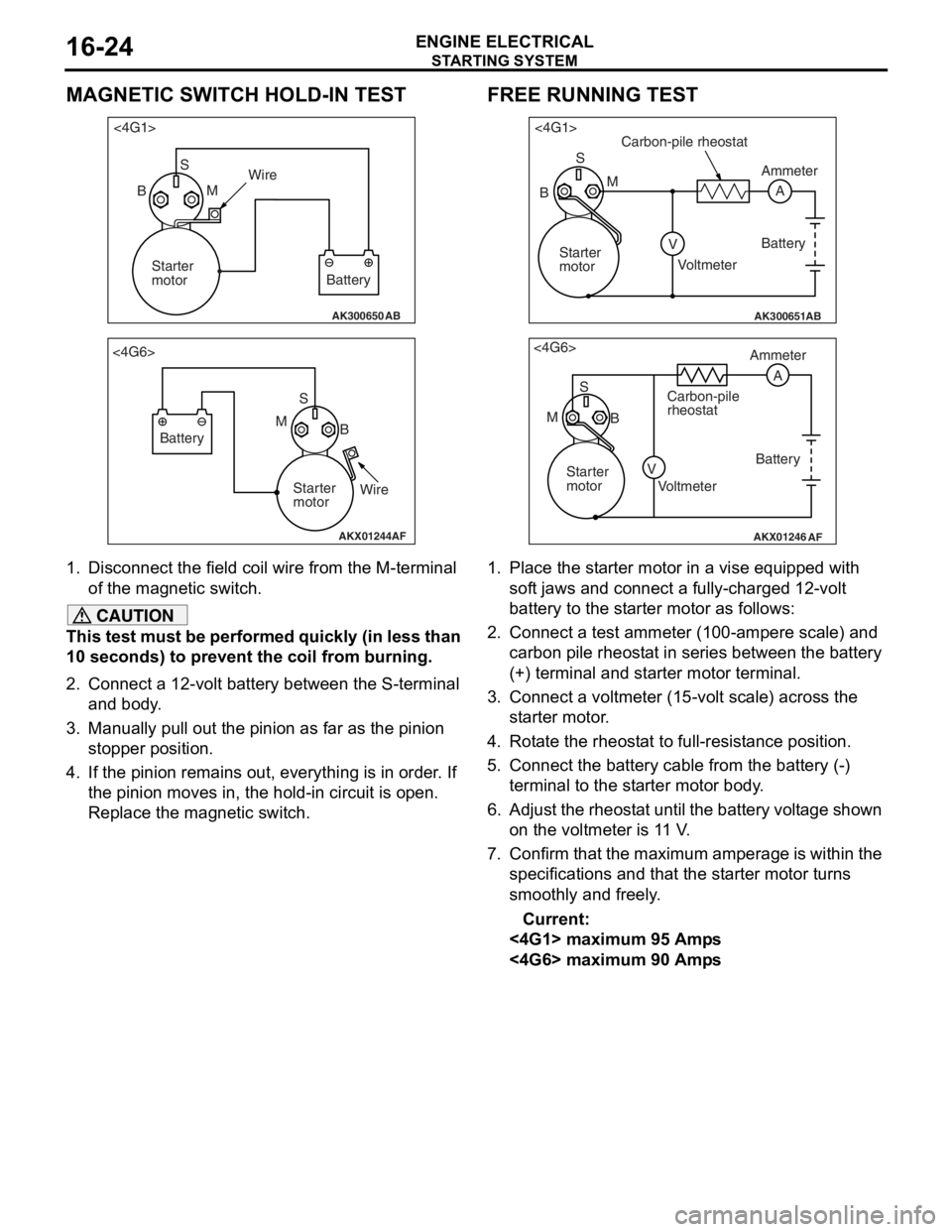
1.
Disco nnect the field coil wire f r om th e M-te rmin al
of the magnet ic switch.
CAUTION
This test must be performed quickly (in less than
10 seconds) to prevent the coil from burning.
2. Connect a 12-volt battery between the S-terminal and body.
3. Manually pull out the pinion as far as the pinion stopper position.
4. If the pinion remains out, everything is in order. If
the pinion moves in, the hold-in circuit is open.
Replace the magnetic switch.
FREE RUNNING TEST
AK300651AB
<4G1>
S
A
M
V
B
Carbon-pile rheostat
Battery
Voltmeter Ammeter
Starter
motor
AKX01246
<4G6> S
M B Ammeter
Carbon-pile
rheostat
Battery
Starter
motor Voltmeter
AF
A
V
1. Place the starter motor in a vise equipped with soft jaws and connect a fully-charged 12-volt
battery to the starter motor as follows:
2. Connect a test ammeter (100-ampere scale) and carbon pile rheostat in series between the battery
(+) terminal and starter motor terminal.
3. Connect a voltmeter (15-volt scale) across the starter motor.
4. Rotate the rheostat to full-resistance position.
5. Connect the battery c able from the battery (-)
terminal to the starter motor body.
6. Adjust the rheostat until the battery voltage shown
on the voltmeter is 11 V.
7. Confirm that the maximum amperage is within the specifications and that the starter motor turns
smoothly and freely.
Current:
<4G1> maximum 95 Amps
<4G6> maximum 90 Amps
Page 88 of 800
STARTING SYSTEM
ENGINE ELECTRICAL16-26
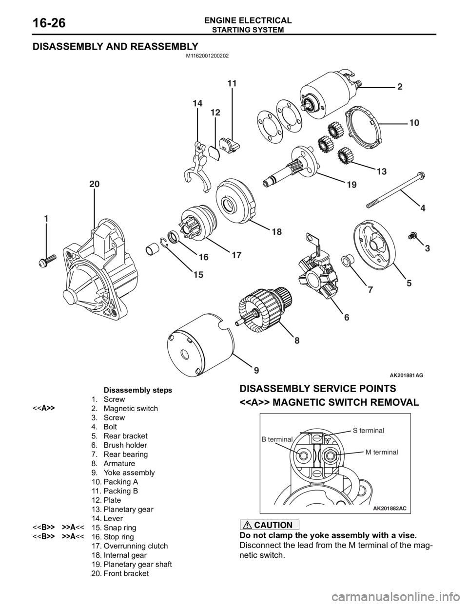
DISASSEMBLY AND REASSEMBLY
M1162001200202
AK201881
141211
20
1
1516
17 18 19
13 10
2
43
5
7
6
8
9
AG
Disassembly steps
1.Screw
<>2.Magnetic switch
3.Screw
4.Bolt
5.Rear bracket
6.Brush holder
7.Rear bearing
8.Armature
9.Yoke assembly
10.Packing A
11 .Packing B
12.Plate
13.Planetary gear
14.Lever
<>>>A<<15.Snap ring
<>>>A<<16.Stop ring
17.Overrunning clutch
18.Internal gear
19.Planetary gear shaft
20.Front bracket
DISASSEMBL Y SER V ICE POINTS
<> MA GNETIC SW ITCH REM O V A L
AK201882
B terminal
M terminal
S terminal
AC
CAUTION
Do not clamp the yoke assembly with a vise.
Disconnect the lead from the M terminal of the mag-
netic switch.
Page 89 of 800
STARTING SYSTEM
ENGINE ELECTRICAL16-27
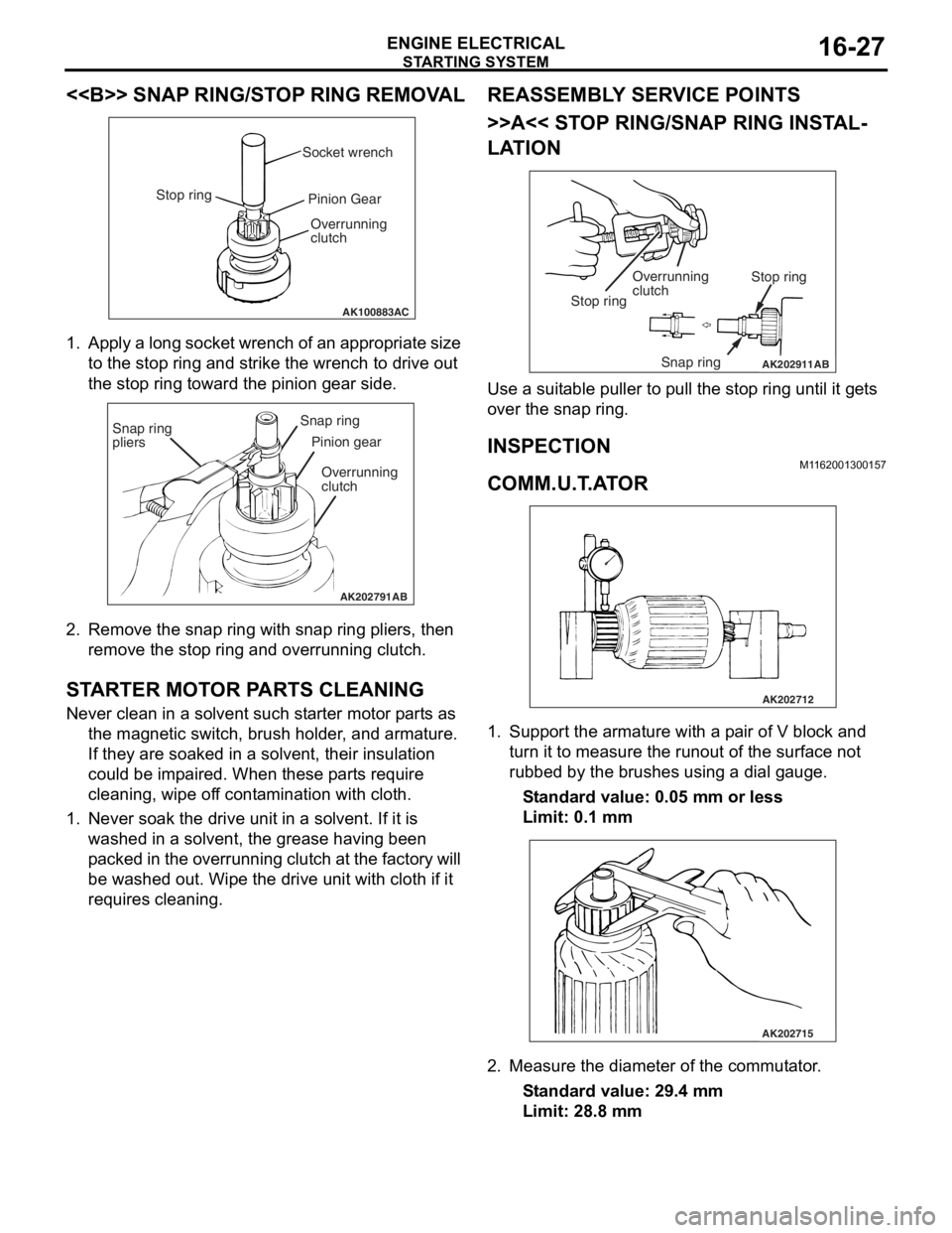
<> SNAP RING/STOP RING REMOVAL
AK100883AC
Socket wrench
Stop ring Pinion Gear
Overrunning
clutch
1. Ap ply a lo ng socket wr ench o f a n ap pro p ria t e size
to the stop ring and strike th e wrench to drive out
th e sto p ring toward th e pin i on g ear side.
AK202791
Snap ring
pliersSnap ring
Pinion gear
Overrunning
clutch
AB
2. Remove the snap ring with sna p ring pliers, th en
remove the stop ring an d overrunning clutch.
STARTER MOT O R P ARTS CLEANING
Never clean in a solvent such st arte r moto r p a rt s as
th e ma gnetic switch, brush hold e r , and arma ture.
If they are soake d in a solven t, their insulat i on
could be imp a ire d . When these p a rt s requ ire
clean ing, wipe of f co nt a m in ation with cloth .
1.Never so ak th e drive un it in a solve n t. If it is
washed in a solvent, th e grea se ha vin g been
p a cke d in th e over run n ing clutch at t he fa ct or y will
be washe d out. Wipe t he drive u n it with cloth if it
req u ires cleaning.
REASSEM BL Y SER V ICE POINT S
>>A<< STOP RING/SNAP RING INST AL-
LATION
AK202911
Overrunning
clutch Stop ring
Snap ring
Stop ring
AB
Use a suit
able puller to pull the stop ring u n til it ge t s
over t
he snap ring.
INSPECTION
M1162 0013 0015 7
COMM.U.T .A T O R
AK202712
1.Sup port the arma ture with a p a ir o f V block a nd
tu rn it t o mea s ure the run out of the surface not
ru bbed b y the brushes u s in g a dial g auge.
St andard va lue: 0.0 5 mm o r l ess
Limit: 0.1 mm
AK202715
2.Measure the diameter o f the commut ator .
St andard va lue: 29 .4 mm
Limit: 28.8 mm
Page 242 of 800
ON-VEHICLE SERVICE
POWER STEERING37-12
TIE ROD END BALL JOINT TURNING
TORQUE CHECK
M1372001500554
CAUTION
•Do not remove the tie rod end nut from the
ball joint. Loosen it and use special tool to
avoid possible damage to the ball joint
threads.
•
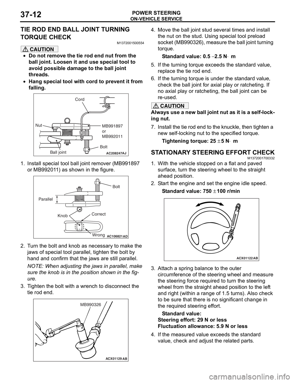
AC208247AJ
CordBoltMB991897
or
MB992011
Nut
Ball joint
Hang special tool with cord to prevent it from
falling.
1. Install special tool ball joint remover (MB991897 or MB992011) as shown in the figure.
AC106821
Knob
Parallel
Bolt
Correct Wrong
AD
2. Turn the bolt and knob as necessary to make the jaws of special tool parallel, tighten the bolt by
hand and confirm that the jaws are still parallel.
NOTE: When adjusting the jaws in parallel, make
sure the knob is in the position shown in the fig
-
ure.
3. Tighten the bolt with a wrench to disconnect the tie rod end.
ACX01129 AB
MB990326
4. Move the ball joint stud several times and install
the nut on the stud. Using special tool preload
socket (MB990326), measure the ball joint turning
torque.
Standard value: 0.5 − 2.5 N⋅m
5. If the turning torque exceeds the standard value, replace the tie rod end.
6. If the turning torque is under the standard value, check the ball joint for axial play or ratcheting. If
no axial play or ratcheting, the ball joint can be
re-used.
CAUTION
Always use a new ball joint nut as it is a self-lock-
ing nut.
7. Install the tie rod end to the knuckle, then tighten a new self-locking nut to the specified torque.
Tightening torque: 25 ± 5 N⋅m
STATIONARY STEERING EFFORT CHECKM1372001700332
1. With the vehicle stopped on a flat and paved
surface, turn the steering wheel to the straight
ahead position.
2. Start the engine and set the engine idle speed.
Standard value: 750 ± 100 r/min
ACX01122 AB
3. Attach a spring balance to the outer
circumference of the steering wheel and measure
the steering force required to turn the steering
wheel from the straight ahead position to the left
and right (within a range of 1.5 turns). Also check
to be sure that there is no significant change in
the required steering effort.
Standard value:
Steering effort: 29 N or less
Fluctuation allowance: 5.9 N or less
4. If the measured value exceeds the standard value, check and adjust the related parts.
Page 244 of 800
ON-VEHICLE SERVICE
POWER STEERING37-14
POWER STEERING SYSTEM AIR
BLEEDING
M1372002200330
Perform air bleeding procedure as necessary after
replacing the steering gear or the steering fluid lines.
1. Raise and support the front wheels.
2. Disconnect the ignition coil connectors (Refer to GROUP 16, Ignition Coil
P.16-38 or P.16-39).
CAUTION
Perform air bleeding only while cranking the
engine. If air bleeding is performed while the
engine is running, air could enter the fluid. Dur
-
ing air bleeding, refill the steering fluid supply so
that the level never falls below the "MIN" mark on
the oil reservoir.
3. Turn the steering wheel all the way to the left and
right five or six times wh ile using the starter motor
to crank the engine intermittently several times
(for 15 to 20 seconds).
4. Connect the ignition coil connectors (Refer to GROUP 16, Ignition Coil
P.16-38 or P.16-39).
5. Start the engine (idling).
6. Turn the steering wheel to the left and right until there are no air bubbles in the oil reservoir.
7. Confirm that the fluid is not milky, and that the level is between "MAX" and "MIN" marks.
8. Confirm that there is very little change in the fluid
level when the steering wheel is turned left and
right.
CAUTION
If the fluid level rises suddenly after the engine is
stopped, the air has not been completely bled. If
air bleeding is not complete, there will be abnor
-
mal noises from the pump and the flow-control
valve, and this condition could cause reduce the
life of the power steering components.
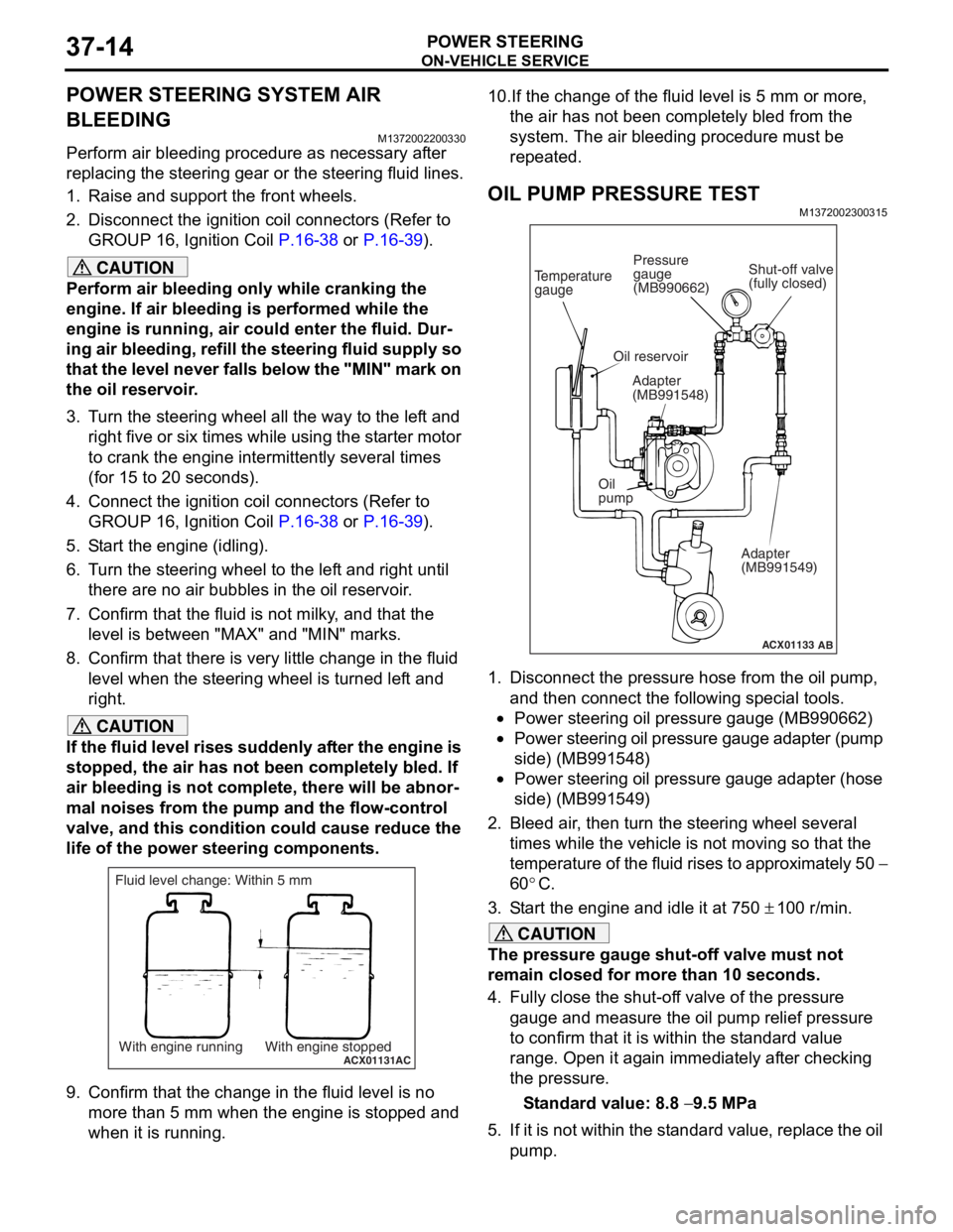
ACX01131With engine running With engine stoppedAC
Fluid level change: Within 5 mm
9. Confirm that the change in the fluid level is no more than 5 mm when the engine is stopped and
when it is running.
10.If the change of the fluid level is 5 mm or more,
the air has not been completely bled from the
system. The air bleeding procedure must be
repeated.
OIL PUMP PRESSURE TEST
M1372002300315
ACX01133
Temperature
gauge
Oil reservoir
Adapter
(MB991548)
Oil
pump Adapter
(MB991549)
AB
Shut-off valve
(fully closed)
Pressure
gauge
(MB990662)
1. Disconnect the pressure hose from the oil pump,
and then connect the following special tools.
•Power steering oil pressure gauge (MB990662)
•Power steering oil pressure gauge adapter (pump
side) (MB991548)
•Power steering oil pressure gauge adapter (hose
side) (MB991549)
2. Bleed air, then turn the steering wheel several times while the vehicle is not moving so that the
temperature of the fluid rises to approximately 50
−
60
°C.
3. Start the engine and idle it at 750 ± 100 r/min.
CAUTION
The pressure gauge shut-off valve must not
remain closed for more than 10 seconds.
4. Fully close the shut-off valve of the pressure gauge and measure the oil pump relief pressure
to confirm that it is within the standard value
range. Open it again immediately after checking
the pressure.
Standard value: 8.8 − 9.5 MPa
5. If it is not within the standard value, replace the oil pump.
Page 286 of 800
WINDOW GLASS
BODY42-14
CAUTION•
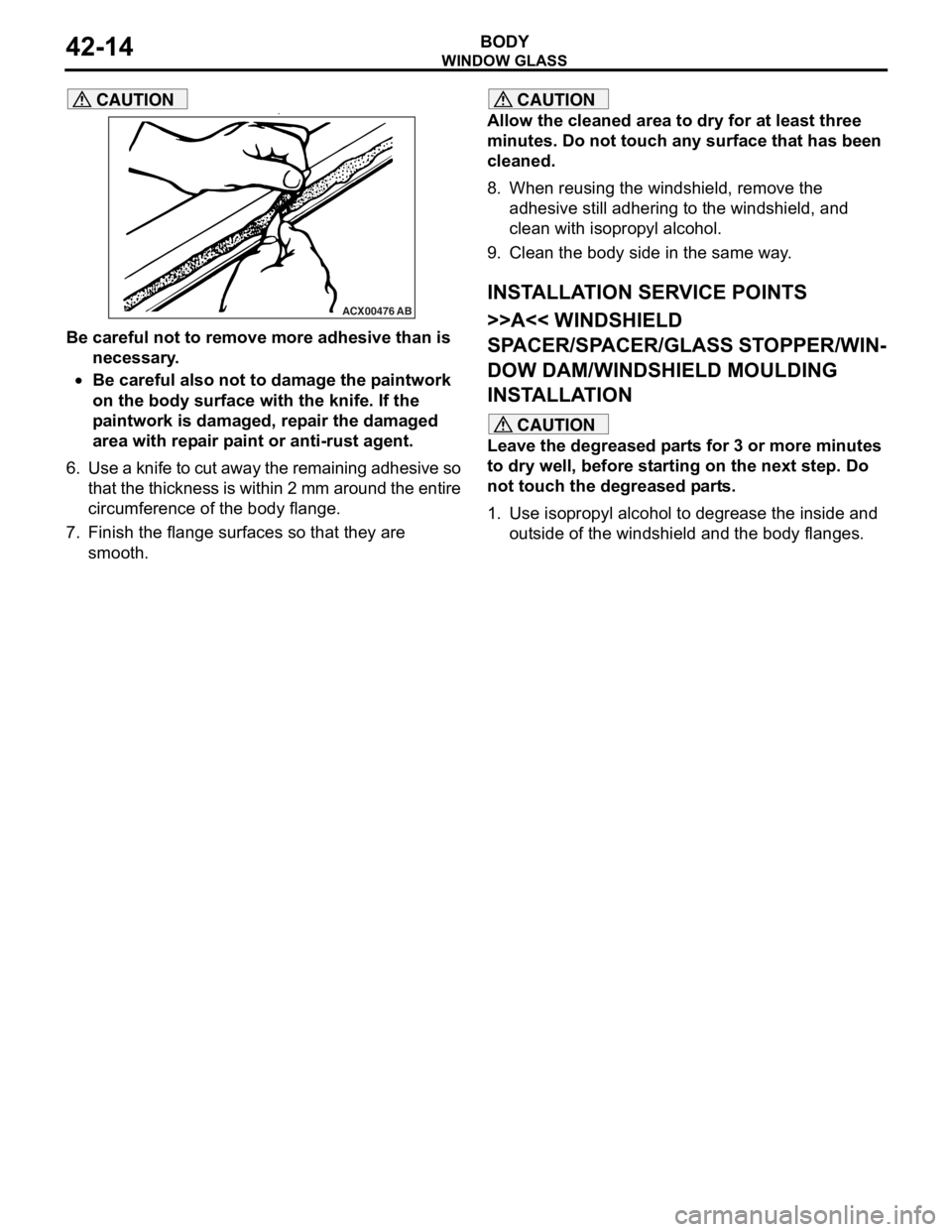
ACX00476AB
Be careful not to remove more adhesive than is
necessary.
•Be careful also not to damage the paintwork
on the body surface with the knife. If the
paintwork is damaged, repair the damaged
area with repair paint or anti-rust agent.
6. Use a knife to cut away the remaining adhesive so
that the thickness is within 2 mm around the entire
circumference of the body flange.
7. Finish the flange surfaces so that they are smooth.
CAUTION
Allow the cleaned area to dry for at least three
minutes. Do not touch any surface that has been
cleaned.
8. When reusing the windshield, remove the adhesive still adhering to the windshield, and
clean with isopropyl alcohol.
9. Clean the body side in the same way.
INSTALLATION SERVICE POINTS
>>A<< WINDSHIELD
SPACER/SPACER/GLASS STOPPER/WIN
-
DOW DAM/WINDSHIELD MOULDING
INSTALLATION
CAUTION
Leave the degreased parts for 3 or more minutes
to dry well, before starting on the next step. Do
not touch the degreased parts.
1. Use isopropyl alcohol to degrease the inside and outside of the windshi eld and the body flanges.
Page 290 of 800
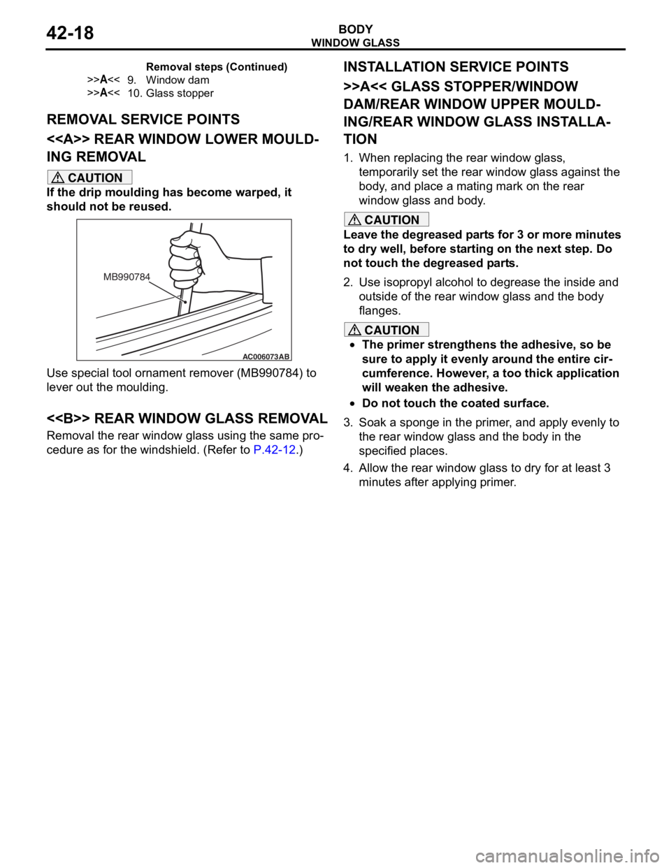
Page 296 of 800
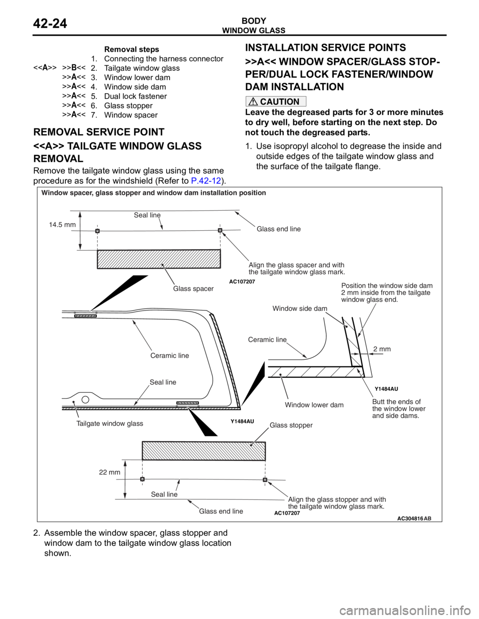
Removal steps
1.Connecting the harness connector
<>>>B<<2.Tailgate window glass
>>A<<3.Window lower dam
>>A<<4.Window side dam
>>A<<5.Dual lock fastener
>>A<<6.Glass stopper
>>A<<7.Window spacer
WI ND OW GLAS S
BODY42-24
REMOVA L SER V ICE POINT
<> TA ILGA TE WINDOW GLASS
REMOV
A L
Remove the t a ilgate window g l ass using the same
proce
dure as for th e windshie l d (Refe r to
P.42-12).
INSTALLA T ION SER VICE POINTS
>>A<< WI NDOW SP ACER/GLASS ST OP-
PER/DUAL LOCK FA STENER/WINDOW
DAM INST
ALLA TION
CAUTION
Leave the degreased parts for 3 or more minutes
to dry well, before starting on the next step. Do
not touch the degreased parts.
1. Use isopropyl alcohol to degrease the inside and outside edges of the tailgate window glass and
the surface of the tailgate flange.
AC107207
AC107207
Y1484AU Y1484AU
AC304816
AB
Glass stopper
Glass spacer
Seal line Ceramic line
Ceramic lineGlass end line
Glass end line
Window spacer, glass stopper and window dam installation position
Align the glass spacer and with
the tailgate window glass mark.Position the window side dam
2 mm inside from the tailgate
window glass end.
Butt the ends of
the window lower
and side dams.
Align the glass stopper and with
the tailgate window glass mark.
Seal line
Seal line
22 mm
14.5 mm
2 mm
Tailgate window glass
Window lower dam
Window side dam
2. Assemble the window spacer, glass stopper and
window dam to the tailgate window glass location
shown.