clock MITSUBISHI LANCER IX 2006 Service Manual
[x] Cancel search | Manufacturer: MITSUBISHI, Model Year: 2006, Model line: LANCER IX, Model: MITSUBISHI LANCER IX 2006Pages: 800, PDF Size: 45.03 MB
Page 35 of 800
ON-VEHICLE SERVICE
ENGINE COOLING14-21
ON-VEHICLE SERVICE
ENGINE COOLANT LEAK CHECKM1141001000300
WARNING
When pressure testing the cooling system,
slowly release cooling system pressure to
avoid getting burned by hot coolant.
CAUTION
•Be sure to completely clean away any mois-
ture from the places checked.
•When the tester is taken out, be careful not to
spill any coolant.
•
ACX01844
Cap adapter
Adapter
AC
Be careful when installing and removing the
tester and when testing not to deform the
filler neck of the radiator.
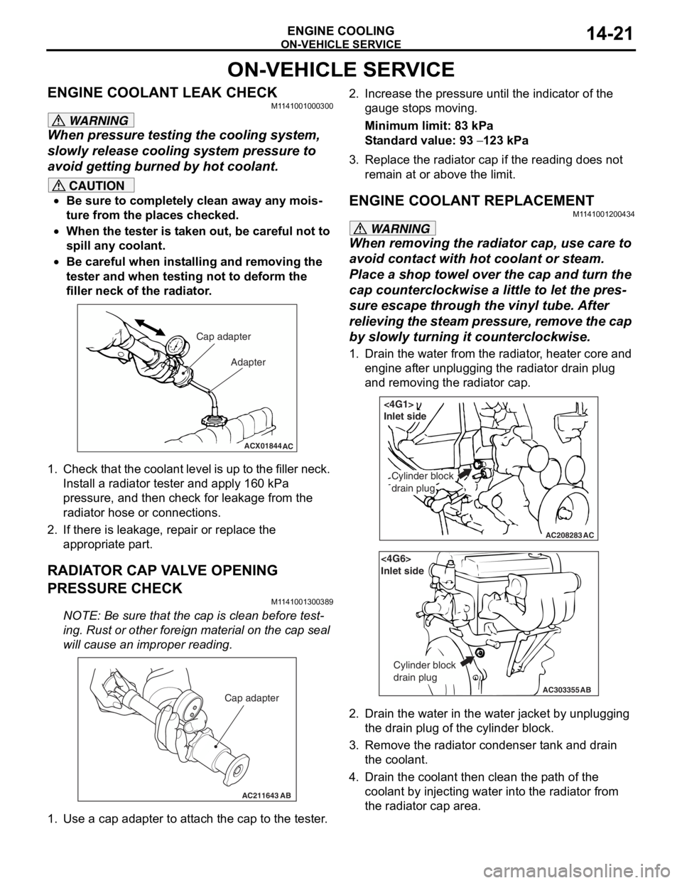
1. Check that the coolant leve l is up to the filler neck.
Install a radiator tester and apply 160 kPa
pressure, and then check for leakage from the
radiator hose or connections.
2. If there is leakage, repair or replace the
appropriate part.
RADIATOR CAP VALVE OPENING
PRESSURE CHECK
M1141001300389
NOTE: Be sure that the cap is clean before test-
ing. Rust or other foreign material on the cap seal
will cause an improper reading.
AC211643AB
Cap adapter
1. Use a cap adapter to attach the cap to the tester.
2. Increase the pressure until the indicator of the gauge stops moving.
Minimum limit: 83 kPa
Standard value: 93 − 123 kPa
3. Replace the radiator cap if the reading does not remain at or above the limit.
ENGINE COOLANT REPLACEMENT
M1141001200434
WARNING
When removing the radiator cap, use care to
avoid contact with hot coolant or steam.
Place a shop towel over the cap and turn the
cap counterclockwise a little to let the pres
-
sure escape through the vinyl tube. After
relieving the steam pres sure, remove the cap
by slowly turning it counterclockwise.
1. Drain the water from the radiator, heater core and
engine after unplugging the radiator drain plug
and removing the radiator cap.
AC208283AC
Cylinder block
drain plug
<4G1>
Inlet side
AC303355
<4G6>
Inlet side
Cylinder block
drain plug
AB
2. Drain the water in the water jacket by unplugging the drain plug of the cylinder block.
3. Remove the radiator condenser tank and drain
the coolant.
4. Drain the coolant then clean the path of the coolant by injecting water into the radiator from
the radiator cap area.
Page 90 of 800
AK202711
SegmentUndercut
Mica
AB
ST ARTING SYS TEM
ENGINE ELECTRICAL16-28
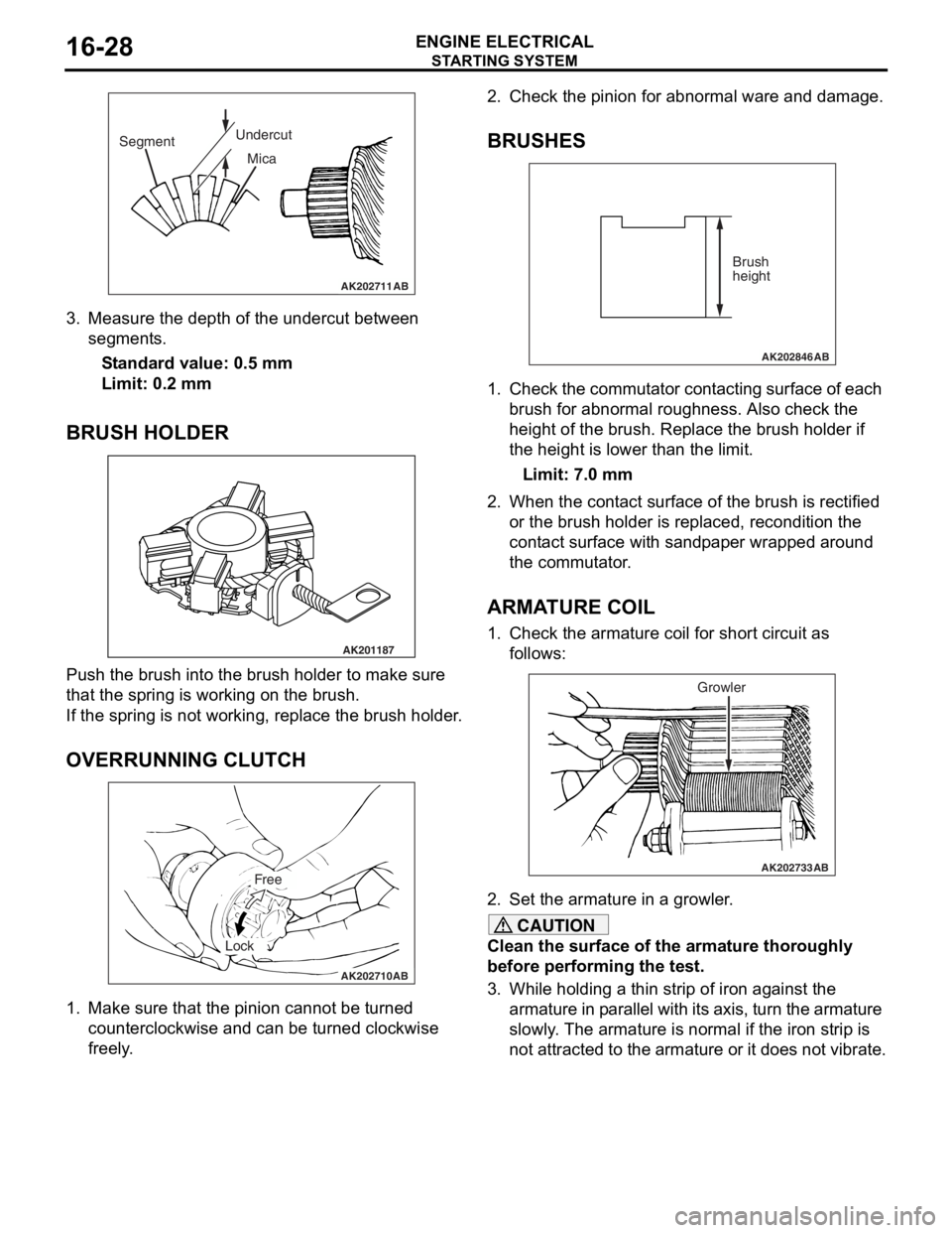
3.Measure the depth of the undercut be twe en
segment s.
St andard va lue: 0.5 mm
Limit: 0.2 mm
BRUSH HOLDER
AK201187
Push th e brush in to the b r ush hold e r to make sure
that the
spring is working o n the b r ush.
If the spring is not working, repla c e th e brush holder .
OVERRUNNING CLUTCH
AK202710
Free
Lock
AB
1.Make sure that th e pin i on canno t be tu rned
counte r clo ckwise a nd ca n be tu rned clockwise
fre e ly .
2.Check t he pinion for abn ormal ware an d damage.
BRUSHES
AK202846
Brush
height
AB
1.Che ck the commut ator con t a c tin g surface of each
b r ush f o r abno rmal rough ness. Also ch eck the
h e ight of the brush . Replace th e brush holder if
th e height is lo we r than t he limit.
Limit: 7.0 mm
2.Wh en the con t act su rface of the brush is rectified
o r the bru s h h o lder is re placed, re cond itio n the
cont act surfa c e wit h san d p a p e r wrapped around
th e co mmu t a t o r .
ARMATURE COIL
1.Check t he armature coil for short circuit a s
fo llows:
AK202733
Growler
AB
2.Set the armature in a growler .
CAUTION
Clean the surface of the armature thoroughly
before performing the test.
3. While holding a thin strip of iron against the
armature in parallel with it s axis, turn the armature
slowly. The armature is normal if the iron strip is
not attracted to the armature or it does not vibrate.
Page 178 of 800
CROSSMEMBER
POWER PLANT MOUNT32-8
INSTALLATION SERVICE POINTS
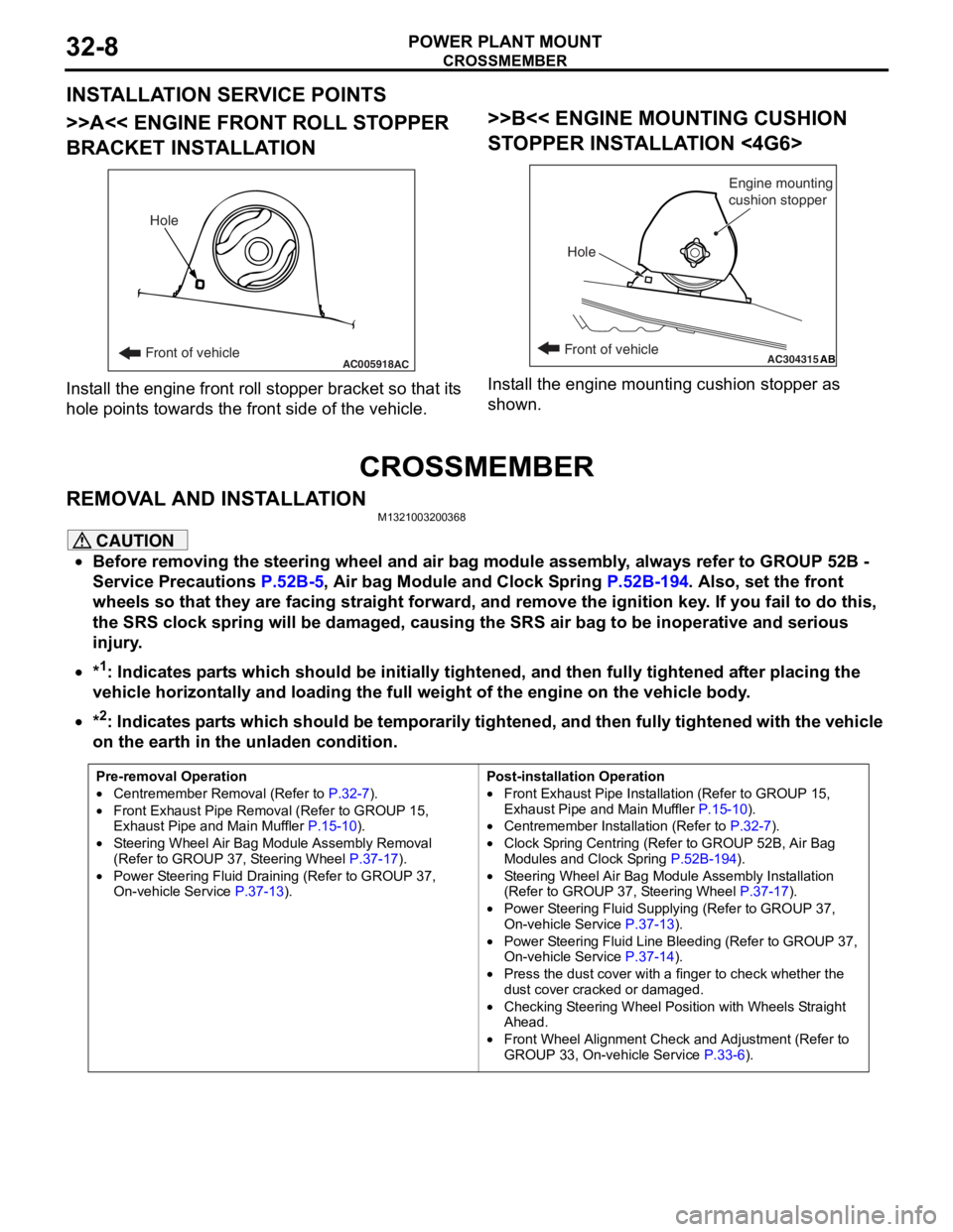
>>A<< ENGINE FRONT ROLL STOPPER
BRACKET INSTALLATION
AC005918Front of vehicleHoleAC
Inst
all th e en gine fron t roll stop per b r acket so that it s
hole
point s towards the fro n t side of the vehicle.
>>B<< ENGINE MOUNTING CUSHION
ST
OPPER INST ALLA TION <4G6>
AC304315ABFront of vehicle
Hole Engine mounting
cushion stopper
Inst
all the e ngin e mo untin g cushio n sto pper a s
shown.
CROSSMEMBER
REMOVA L AND INST ALLA TIONM13210032 0036 8
CAUTION
•Before removing the steering wheel and air bag module assembly, always refer to GROUP 52B -
Service Precautions
P.52B-5, Air bag Module and Clock Spring P.52B-194. Also, set the front
wheels so that they are facing straight forward, and remove the ignition key. If you fail to do this,
the SRS clock spring will be damaged, causing the SRS air bag to be inoperative and serious
injury.
•*1: Indicates parts which should be initially tightened, and then fully tightened after placing the
vehicle horizontally and loading the full weight of the engine on the vehicle body.
•
Pre-removal Operation
•Centremember Removal (Refer to P.32-7).
•Front Exhaust Pipe Remova l (Refer to GROUP 15,
Exhaust Pipe and Main Muffler P.15-10).
•Steering Wheel Air Bag Mo dule Assembly Removal
(Refer to GROUP 37, Steering Wheel P.37-17).
•Power Steering Fluid Draining (Refer to GROUP 37,
On-vehicle Service P.37-13).
Post-installation Operation
•Front Exhaust Pipe Installation (Refer to GROUP 15,
Exhaust Pipe and Main Muffler
P.15-10).
•Centremember Installation (Refer to P.32-7).
•Clock Spring Centring (Refer to GROUP 52B, Air Bag
Modules and Clock Spring P.52B-194).
•Steering Wheel Air Bag Module Assembly Installation
(Refer to GROUP 37, Steering Wheel P.37-17).
•Power Steering Fluid Supplying (Refer to GROUP 37,
On-vehicle Service P.37-13).
•Power Steering Fluid Line Bleeding (Refer to GROUP 37,
On-vehicle Service P.37-14).
•Press the dust cover with a finger to check whether the
dust cover cracked or damaged.
•Checking Steering Wheel Position with Wheels Straight
Ahead.
•Front Wheel Alignment Check and Adjustment (Refer to
GROUP 33, On-vehicle Service P.33-6).
*2: Indicates parts which should be temporarily tightened, and then fully tightened with the vehicle
on the earth in the unladen condition.
Page 183 of 800
33-1
GROUP 33
FRONT
SUSPENSION
CONTENTS
GENERAL INFORMATIO N . . . . . . . .33-2
SERVICE SPECIFICATIONS . . . . . . .33-3
LUBRICANT . . . . . . . . . . . . . . . . . . . .33-3
SPECIAL TOOLS . . . . . . . . . . . . . . . .33-4
ON-VEHICLE SERVICE . . . . . . . . . . .33-6
FRONT WHEEL ALIGNMENT CHECK AND
ADJUSTMENT . . . . . . . . . . . . . . . . . . . . . . 33-6
LOWER ARM BALL JOINT AXIAL PLAY
CHECK . . . . . . . . . . . . . . . . . . . . . . . . . . . . 33-7
LOWER ARM BALL JOINT COVER
CHECK . . . . . . . . . . . . . . . . . . . . . . . . . . . . 33-7
STRUT ASSEMBLY . . . . . . . . . . . . . .33-7
REMOVAL AND INSTALLATION . . . . . . . . 33-7
INSPECTION. . . . . . . . . . . . . . . . . . . . . . . . 33-7
DISASSEMBLY AND REASSEMBLY . . . . . 33-8
INSPECTION. . . . . . . . . . . . . . . . . . . . . . . . 33-10
LOWER ARM . . . . . . . . . . . . . . . . . . .33-11
REMOVAL AND INSTALLATION . . . . . . . . 33-11
INSPECTION. . . . . . . . . . . . . . . . . . . . . . . . 33-12
LOWER ARM BALL JOINT COVER
REPLACEMENT . . . . . . . . . . . . . . . . . . . . . 33-12
LOWER ARM BUSHING (REAR)
REPLACEMENT . . . . . . . . . . . . . . . . . . . . . 33-13
STABILIZER BAR. . . . . . . . . . . . . . . .33-14
REMOVAL AND INSTALLATION . . . . . . . . 33-14
INSPECTION. . . . . . . . . . . . . . . . . . . . . . . . 33-16
WARNINGS REGARDING SERVICING OF SUPPLEMENTAL RESTRAINT SYSTEM (SRS) EQUIPPED VEHICLES
WARNING
•Improper service or maintenance of any component of the SRS, or any SRS-related component, can lead to
personal injury or death to service personnel (from inad vertent firing of the air bag) or to the driver and
paassenger (from rendering the SRS inoperative).
•Service or maintenance of any SRS component or SRS-related component must be performed only at an
authorized MITSUBISHI dealer.
•MITSUBISHI dealer personnel must thoroughly review this manual, and especially its GROUP 52B - Supplemental
Restraint System (SRS) before beginning any service or maintenance of any component of the SRS or any
SRS-related component.
NOTE
The SRS includes the following components: SRS air bag control unit, SRS warning light, front impact sensors, air bag module,
clock spring, and interconnecting wiring. Other SRS-related components (that may have to be removed/installed in connection
with SRS service or maintenance) are indicated in the table of contents by an asterisk (*).
Page 196 of 800
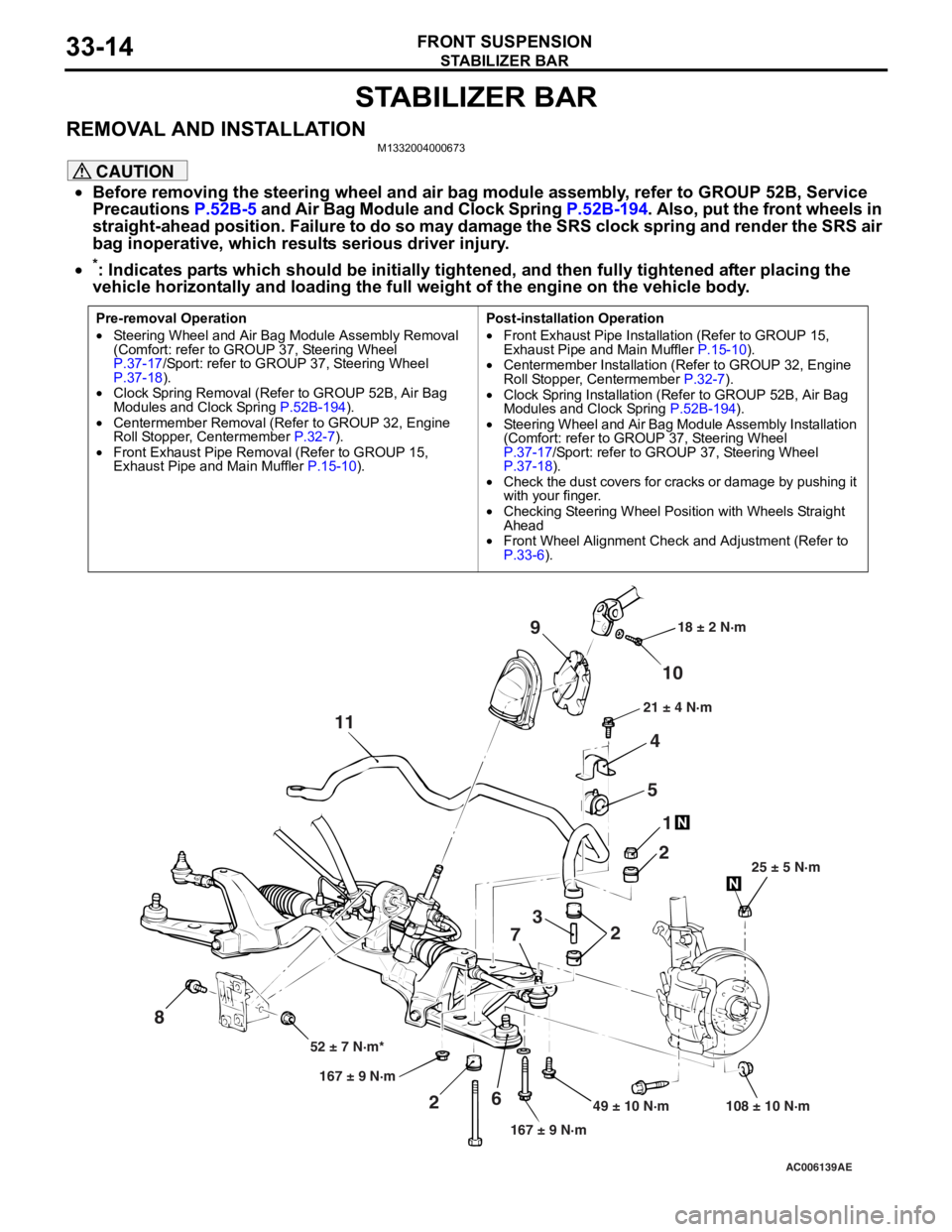
STABILIZER BAR
FRONT SUSPENSION33-14
STABILIZER BAR
REMOVAL AND INSTALLATIONM1332004000673
CAUTION
•Before removing the steering wheel and air bag module assembly, refer to GROUP 52B, Service
Precautions
P.52B-5 and Air Bag Module and Clock Spring P.52B-194. Also, put the front wheels in
straight-ahead position. Failure to do so may damage the SRS clock spring and render the SRS air
bag inoperative, which results serious driver injury.
•
Pre-removal Operation
•Steering Wheel and Air Bag Module Assembly Removal
(Comfort: refer to GROUP 37, Steering Wheel
P.37-17/Sport: refer to GROUP 37, Steering Wheel P.37-18).•Clock Spring Removal (Refer to GROUP 52B, Air Bag
Modules and Clock Spring P.52B-194).
•Centermember Removal (Ref er to GROUP 32, Engine
Roll Stopper, Centermember P.32-7).
•Front Exhaust Pipe Remova l (Refer to GROUP 15,
Exhaust Pipe and Main Muffler P.15-10).
Post-installation Operation
•Front Exhaust Pipe Installation (Refer to GROUP 15,
Exhaust Pipe and Main Muffler P.15-10).•Centermember Installation (Refer to GROUP 32, Engine
Roll Stopper, Centermember P.32-7).
•Clock Spring Installation (Refer to GROUP 52B, Air Bag
Modules and Clock Spring P.52B-194).
•Steering Wheel and Air Bag Module Assembly Installation
(Comfort: refer to GROUP 37, Steering Wheel
P.37-17/Sport: refer to GROUP 37, Steering Wheel P.37-18).•Check the dust covers for cracks or damage by pushing it
with your finger.
•Checking Steering Wheel Position with Wheels Straight
Ahead
•Front Wheel Alignment Check and Adjustment (Refer to P.33-6).
AC006139 AE
49 ± 10 N·m 108 ± 10 N·m
167 ± 9 N·m
167 ± 9 N·m
52 ± 7 N·m* 25 ± 5 N·m
21 ± 4 N·m
18 ± 2 N·m
10
9
4
5 1
2
2
3
7
6
2
11
8
*: Indicates parts which should be initially tightened, and then fully tightened after placing the
vehicle horizontally and loading the full weight of the engine on the vehicle body.
Page 204 of 800
ON-VEHICLE SERVICE
REAR SUSPENSION34-6
ON-VEHICLE SERVICE
REAR WHEEL ALIGNMENT CHECK AND
ADJUSTMENT
M1341011000372
Measure wheel alignment with an alignment equip-
ment on level earth.
The rear suspension, wheels, and tyres should be
serviced to the normal condition prior to wheel align
-
ment measurement.
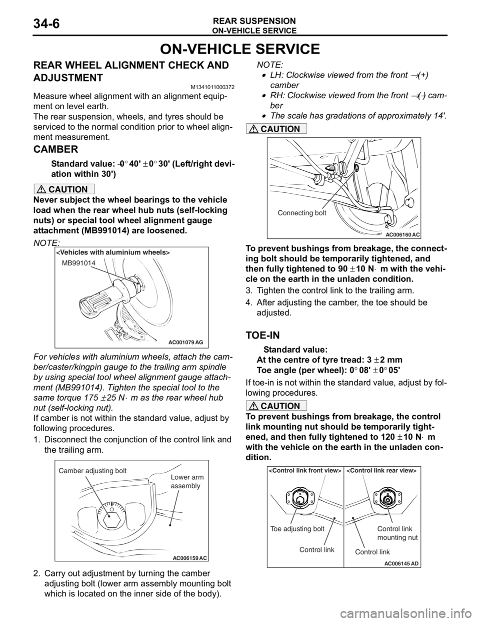
CAMBER
Standard value: −0°40' ± 0°30' (Left/right devi-
ation within 30')
CAUTION
Never subject the wheel bearings to the vehicle
load when the rear wheel hub nuts (self-locking
nuts) or special tool wheel alignment gauge
attachment (MB991014) are loosened.
NOTE:
AC001079
MB991014
AG
For vehicles with aluminium wheels, attach the cam-
ber/caster/kingpin gauge to the trailing arm spindle
by using special tool wheel alignment gauge attach
-
ment (MB991014). Tighten the special tool to the
same torque 175
± 25 N⋅m as the rear wheel hub
nut (self-locking nut).
If camber is not within the standard value, adjust by
following procedures.
1. Disconnect the conjunction of the control link and the trailing arm.
AC006159 AC
Camber adjusting bolt
Lower arm
assembly
2. Carry out adjustment by turning the camber
adjusting bolt (lower arm assembly mounting bolt
which is located on the inner side of the body).
NOTE: .
•LH: Clockwise viewed from the front → (+)
camber
•RH: Clockwise viewed from the front → (−) cam-
ber
•
AC006160 AC
Connecting bolt
The scale has gradations of approximately 14'.
CAUTION
To prevent bushings from breakage, the connect-
ing bolt should be temporarily tightened, and
then fully tightened to 90
± 10 N⋅m with the vehi-
cle on the earth in the unladen condition.
3. Tighten the control link to the trailing arm.
4. After adjusting the camber, the toe should be
adjusted.
TOE-IN
Standard value:
At the centre of tyre tread: 3 ± 2 mm
Toe angle (per wheel): 0°08' ± 0°05'
If toe-in is not within the standard value, adjust by fol-
lowing procedures.
CAUTION
To prevent bushings from breakage, the control
link mounting nut should be temporarily tight
-
ened, and then fully tightened to 120 ± 10 N⋅m
with the vehicle on the earth in the unladen con
-
dition.
AC006145 AD
Control link
Toe adjusting boltControl link
Control link
mounting nut
Page 205 of 800
ON-VEHICLE SERVICE
REAR SUSPENSION34-7
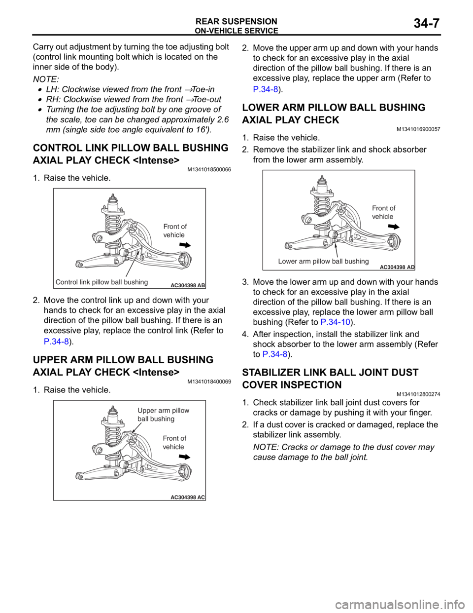
Carry out adjustment by turning the toe adjusting bolt
(control link mounting bolt which is located on the
inner side of the body).
NOTE: .
•LH: Clockwise viewed from the front → To e - i n
•RH: Clockwise viewed from the front → Toe-out
•Turning the toe adjusting bolt by one groove of
the scale, toe can be changed approximately 2.6
mm (single side toe angle equivalent to 16').
CONTROL LINK PILLOW BALL BUSHING
AXIAL PLAY CHECK
M1341018500066
1. Raise the vehicle.
AC304398ABControl link pillow ball bushing
Front of
vehicle
2.Move the control link up and d o wn with your
ha nds to ch eck for an excessive pla y in the a x ia l
direct ion o f the p illow ball bushing . If the r e is an
exce ssive play , re place the cont rol link (Re f er to
P.34-8).
UPPER ARM PILLOW BALL BUSHING
AXIAL PLAY CHECK
M13410184 0006 9
1.Raise th e ve hicle.
AC304398AC
Upper arm pillow
ball bushing
Front of
vehicle
2. Move the up per arm up and down with you r hand s
to che ck for an e xce ssive play in the axial
d i rection o f the p illow ball bushing . If the r e is an
e xce ssive play , re place the upper arm (Refe r to
P.34-8).
LOWER ARM PILLOW BALL BUSHING
AXIAL PLAY CHECK
M13410169 0005 7
1.Raise th e ve hicle.
2.Remove the st a b ilizer link and shock a b sorb er
f r om t h e l o we r arm a s s e mb l y .
AC304398ADLower arm pillow ball bushing
Front of
vehicle
3.Move the lower a r m u p and down with your h ands
to che ck for an e xce ssive play in the axial
d i rection o f the p illow ball bushing . If the r e is an
e xce ssive play , re place the lower a r m pillo w b a ll
b u shing (Refer to
P.34-10).
4.Af ter inspe c tio n , in st all the st a b ilizer link and
shock a b sorb er to the lower arm assembly (Refer
to
P.34-8).
STABILIZER LINK BALL JOINT DUST
COVER INSPECTION
M1341 0128 0027 4
1.Check st abilize r lin k ba ll joint dust covers f o r
cracks o r damage by pushing it wit h you r fing er .
2. If a du st cove r is crack ed or da mag ed, rep l ace t he
st a b ili zer link assembly .
NOTE: Cracks or dama ge to t he dust co ver may
cause damage to the b a ll join t.
Page 231 of 800
37-1
GROUP 37
POWER STEERING
CONTENTS
GENERAL INFORMATION . . . . . . . .37-3
SERVICE SPECIFICATIONS . . . . . . .37-6
LUBRICANTS . . . . . . . . . . . . . . . . . .37-7
SEALANTS . . . . . . . . . . . . . . . . . . . .37-7
SPECIAL TOOLS . . . . . . . . . . . . . . . .37-8
ON-VEHICLE SERVICE . . . . . . . . . . .37-11
STEERING WHEEL FREE PLAY CHECK . 37-11
STEERING ANGLE CHECK . . . . . . . . . . . . 37-11
TIE ROD END BALL JOINT TURNING
TORQUE CHECK . . . . . . . . . . . . . . . . . . . . 37-12
STATIONARY STEERING EFFORT
CHECK . . . . . . . . . . . . . . . . . . . . . . . . . . . . 37-12
STEERING WHEEL RETURN TO
CENTRE CHECK . . . . . . . . . . . . . . . . . . . . 37-13
DRIVE BELT TENSION CHECK. . . . . . . . . 37-13
FLUID LEVEL CHECK . . . . . . . . . . . . . . . . 37-13
FLUID REPLACEMENT . . . . . . . . . . . . . . . 37-13
POWER STEERING SYSTEM AIR
BLEEDING . . . . . . . . . . . . . . . . . . . . . . . . . 37-14
OIL PUMP PRESSURE TEST . . . . . . . . . . 37-14
POWER STEERING PRESSURE
SWITCH CHECK . . . . . . . . . . . . . . . . . . . . . 37-15
TIE ROD END BALL JOINT DUST
COVER CHECK . . . . . . . . . . . . . . . . . . . . . 37-15
STEERING COLUMN SHAFT ASSEMBLY
SHOCK ABSORBING MECHANISM
CHECK . . . . . . . . . . . . . . . . . . . . . . . . . . . . 37-15
STEERING WHEEL . . . . . . . . . . . . . .37-17
REMOVAL AND INSTALLATION
REMOVAL AND INSTALLATION
Continued on next page
WARNINGS REGARDING SERVICING OF SUPPLEMENTAL RESTRAINT SYSTEM (SRS) EQUIPPED VEHICLES
WARNING
•Improper service or maintenance of any component of the SRS, or any SRS-related component, can lead to
personal injury or death to service personnel (from inad vertent firing of the air bag) or to the driver and
paassenger (from renderin g the SRS inoperative).
•Service or maintenance of any SRS component or SRS-related component must be performed only at an
authorized MITSUBISHI dealer.
•MITSUBISHI dealer personnel must thoroughly review th is manual, and especially its GROUP 52B - Supplemental
Restraint System (SRS) before begi nning any service or maintenance of any component of the SRS or any
SRS-related component.
NOTE
The SRS includes the following components: SRS air bag control unit, SRS warning light, front impact sensors, air bag module,
clock spring, and interconnecting wiring. Other SRS-related components (that may have to be removed/installed in connection
with SRS service or maintenance) are indicated in the table of contents by an asterisk (*).
Page 247 of 800
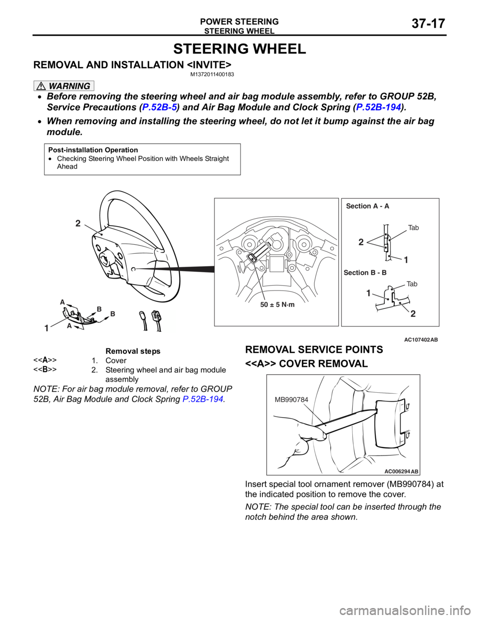
STEERING WHEEL
POWER STEERING37-17
STEERING WHEEL
REMOVAL AND INSTALLATION
WARNING
•Before removing the steering wheel and air bag module assembly, refer to GROUP 52B,
Service Precautions (
P.52B-5) and Air Bag Module and Clock Spring (P.52B-194).
•
Post-installation Operation
•Checking Steering Wheel Position with Wheels Straight
Ahead
AC107402AB
50 ± 5 N·m
1
2
21
1 2
A
A B
B Ta b
Ta b
Section A - A
Section B - B
Removal steps
<>1.Cover
<>2.Steering wheel and air bag module
assembly
When removing and installing the steering whee l, do not let it bump against the air bag
module.
NOTE: For air bag module removal, refer to GROUP
52B, Air Bag Module and Clock Spring
P.52B-194.
REMOVAL SERVICE POINTS
<> COVER REMOVAL
AC006294 AB
MB990784
Insert special tool ornament remover (MB990784) at
the indicated position to remove the cover.
NOTE: The special tool can be inserted through the
notch behind the area shown.
Page 248 of 800
STEERING WHEEL
POWER STEERING37-18
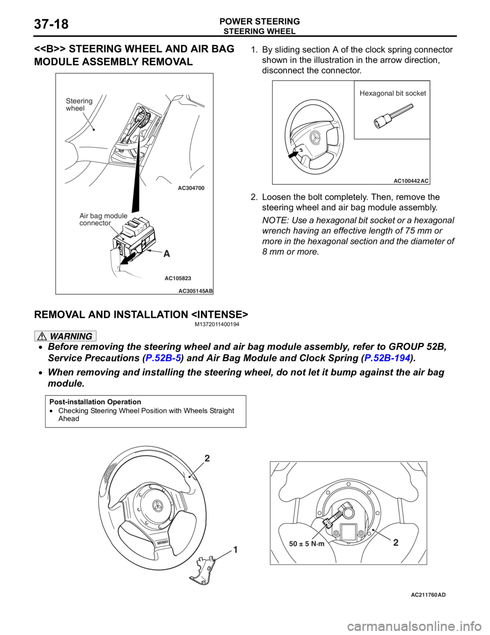
<> STEERING WHEEL AND AIR BAG
MODULE ASSEMBLY REMOVAL
AC105823
AC304700
AC305145AB
A
Steering
wheel
Air bag module
connector
1.By slidin g se ctio n A of the clock spring connector
shown in the illu strat i on in the arrow dire ctio n,
d i sconne ct the con necto r .
AC100442
Hexagonal bit socket
AC
2.L oose n the b o lt comp letely . Then , remo ve th e
steering wheel and air ba g mo dule assembly .
NOTE: Use a hexagon al b i t socket o r a h e xag onal
wren
ch ha vin g an e ffective lengt h of 75 mm or
mo
re in the hexagonal section and t he diameter of
8
mm
or mo re.
REMOV A L AND INST ALLA TION
M137201 14 0019 4
WARNING
•Before removing the steering wheel and air bag module assembly, refer to GROUP 52B,
Service Precautions (
P.52B-5) and Air Bag Module and Clock Spring (P.52B-194).
•
Post-installation Operation
•Checking Steering Wheel Position with Wheels Straight
Ahead
AC211760 AD
50 ± 5 N·m2
1
2
When removing and installing the steering whee
l, do not let it bump against the air bag
module.