Link system MITSUBISHI MIRAGE 2015 6.G User Guide
[x] Cancel search | Manufacturer: MITSUBISHI, Model Year: 2015, Model line: MIRAGE, Model: MITSUBISHI MIRAGE 2015 6.GPages: 300, PDF Size: 43.44 MB
Page 84 of 300
Free-hand Advanced Securi
ty Transmitter (F.A.S.T.-key) (if so equipped)
Features and controls 5-23
5
4. Release in sequence the LOCK and UNLOCK buttons within 10 seconds ofpressing the LOCK button in step 3.
N00544700060
If you are near your vehicle and feel threat-ened, you can acti-vate th
e alarm to call atten-
tion as follows: 1. Press the PANIC button (3) for more than 1 second. 2. The headlights will blink on and off and the horn will sound intermittently forabout 3 minutes. 3. To turn off the alarm, press any button on the remote control transmitter.
N00562000065
Your F.A.S.T.-key operates on a radio fre- quency subject to Fe
deral Communications
Commission (FCC) Rules (For vehicles soldin U.S.A.) and Industry Canada Rules (For vehicles sold in Cana
da). This device com-
plies with Part 15 of FCC Rules and IndustryCanada licence-exem
pt RSS standard(s).
Operation is subject to
the following two con-
ditions.
This device may not
cause harmful inter-
ference. This device must ac
cept any interference
received, including interference that may cause undesired operation of this device.
N00562100066
1. Before replacing the battery, remove staticelectricity from your body by touching a metal grounded object. 2. With the Mitsubishi mark facing you,insert the cloth-cov-ered tip of a flat blade screwdriver into the notch in the case and use it to open the case.
Using the panic alarm
NOTE
The indicator light (4)
comes on each time a
button is pressed. The F.A.S.T.-key can be used from about 40 feet (12 m) away. However, this distance may change if your vehicle is near a TVtransmitting tower, a power station, or a radio station. If the following conditions are observed after pressing the LOCK (1) or UNLOCK (2) but- ton on the remote control transmitter, thebuttery in the F.A.S.T.-key may need to be replaced.
• The doors and the lift
gate cannot be locked
or unlocked. • The panic alarm cannot be operated. • The indicator light
(4) is dim or does not
come on.
If you lose your F.A.S.T.
-key, please contact
an authorized Mitsubish
i Motors dealer for a
replacement. If you wish to obtain an additional F.A.S.T.- key, please contact an
authorized Mitsubishi
Motors dealer. A maximu
m of four F.A.S.T.-
key can be programmed for your vehicle. To use the new remote control transmitters, it is necessary to register
the key with the elec-
tronic immobilizer and
keyless entry system.
Refer to “Electronic immobilizer (Anti-theftstarting system): Customer F.A.S.T.-key pro- gramming” on page 5-20.
General information
NOTE
WA R N I N G Changes or modifica
tions not expressly
approved by the party responsible for compliance could void the user’s authority to operate the equipment.
Procedure for replacing the remote control transmitter bat-tery
BK0212400US.book 23 ページ 2014年4月1日 火曜日 午後2時21分
Page 103 of 300
Continuously variable transmission (CVT) (if so equipped) 5-42 Features and controls
5
Move the lever to this
position only after the
vehicle has come to a complete stop. At this position, the transmission is disen- gaged. It is the same
as the neutral position on
a manual transaxle and should be used whenthe vehicle is not m
oving for an extended
length of time during driving, such as in a traffic jam.
This position is used fo
r most city and high-
way driving. The transmission will automati-cally and continuously ch
ange its gear ratio
depending on road and driving conditions. This position is for use when light engine braking at high-speed is needed, or driving up very steep hills and for
engine braking at low
speeds when descendi
ng steep gradients.
N00549500018 N00574601023
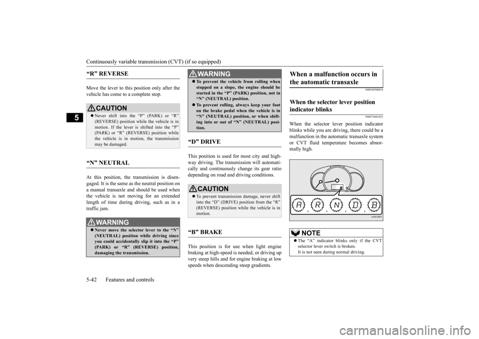
When the selector lever position indicator blinks while you are driving, there could be a malfunction in the automatic transaxle system or CVT fluid temperature becomes abnor- mally high.
“R” REVERSE
CAUTION Never shift into the “P” (PARK) or “R” (REVERSE) position while the vehicle is in motion. If the lever is shifted into the “P”(PARK) or “R” (REVERSE) position while the vehicle is in motion, the transmission may be damaged.
“N” NEUTRAL
WA R N I N G Never move the selector lever to the “N” (NEUTRAL) position while driving since you could accidentally
slip it into the “P”
(PARK) or “R” (REVERSE) position,damaging the transmission.
To prevent the vehicle from rolling when stopped on a slope,
the engine should be
started in the “P” (PARK) position, not in“N” (NEUTRAL) position. To prevent rolling,
always keep your foot
on the brake pedal when the vehicle is in “N” (NEUTRAL) positi
on, or when shift-
ing into or out of “N” (NEUTRAL) posi-tion.
“D” DRIVE
CAUTION To prevent transmission damage, never shift into the “D” (DRIVE) position from the “R”(REVERSE) position while the vehicle is in motion.
“B” BRAKE
WA R N I N G
When a malfunction occurs in the automatic transaxle
When the selector lever position indicator blinks
NOTE
The “A” indicator blinks only if the CVT selector lever switch is broken.It is not seen during normal driving.
BK0212400US.book 42 ページ 2014年4月1日 火曜日 午後2時21分
Page 112 of 300
Active stability control (ASC) Features and controls 5-51
5
N00546500118
N00546600119
If an abnormal condition occurs in the sys- tem, the following indicator will turn on.
N00546300031
When moving out of mud, sand or fresh snow, pressing the acce
lerator pedal may not
allow the engine speed to increase. In suchsituations, temporaril
y turning off ASC with
the “ASC OFF” switch will make it easier to move out your vehicle. If you continue to press the “ASC OFF” switch after the ASC is turned off, the “mis-taken operation protec
tion function” will
activate and the ASC will turn back on.
ASC operation indicator or ASC OFF indicator
-
ASC operation indicator The indicator will blink when the ASC is operating.
-
ASC OFF indicator This indicator will turn on when the ASC is turned off with the “ASCOFF” switch.
CAUTION When indicator bli
nks, ASC is operating,
which means that the road is slippery or that your vehicle’s wheels ar
e beginning to slip.
If this happens, drive
slower with less accel-
erator input.NOTE
NOTE
The indicator may turn on when you start the engine. This means that the battery volt- age momentarily dropped when the enginewas started. It does not
indicate a malfunc-
tion, provided that
the display goes out
immediately. When a compact spare tire has been put on your vehicle, the grippi
ng ability of the tire
will be lower, making it
more likely that the
indicator will blink.
ASC warning indicator
-
ASC indicator
-
ASC OFF indicator
CAUTION The system may be malfunctioning. Park your vehicle in a
safe place and stop the
engine.Restart the engine and check whether the indicator goes out. If th
ey go out, there is no
abnormal condition. If
they do not go out or
appear frequently, it is
not necessary to stop
the vehicle imme
diately, but you should have
your vehicle inspected by an authorizedMitsubishi Motors dealer
or a repair facility
of your choice as soon as possible.
To w i n g
CAUTION When towing the vehicle with only the front wheels or only the rear wheels raised off theground, do not place th
e ignition switch in
the “ON” position or
do not put the operation
mode in ON. Placing
the ignition switch in
the “ON” position or
putting the operation
mode in ON could caus
e the ASC to operate,
resulting in an accident.Note that the correct
towing method depends
on the transmission type
and the vehicle’s
drive configuration. For details, refer to “Towing” on page 8-17.
BK0212400US.book 51 ページ 2014年4月1日 火曜日 午後2時21分
Page 118 of 300
Tire pressure monitoring system (if so equipped)
Features and controls 5-57
5
N00532701347
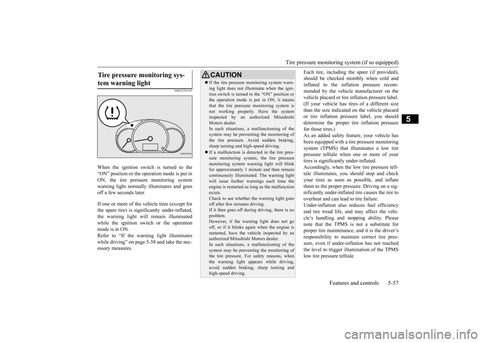
When the ignition switch is turned to the “ON” position or the operation mode is put inON, the tire pressure monitoring system warning light normally
illuminates and goes
off a few seconds later. If one or more of the vehicle tires (except for the spare tire) is significantly under-inflated, the warning light will remain illuminated while the ignition swit
ch or the operation
mode is in ON. Refer to “If the warning light illuminates while driving” on page 5-58 and take the nec-essary measures.
Each tire, including the spare (if provided), should be checked monthly when cold andinflated to the inflation pressure recom- mended by the vehicle manufacturer on the vehicle placard or tire in
flation pressure label.
(If your vehicle has tires of a different size than the size indicate
d on the vehicle placard
or tire inflation pressure label, you shoulddetermine the proper ti
re inflation pressure
for those tires.) As an added safety fe
ature, your vehicle has
been equipped with a tire pressure monitoring system (TPMS) that illuminates a low tirepressure telltale when one or more of your tires is significan
tly under-inflated.
Accordingly, when the low tire pressure tell-tale illuminates, you s
hould stop and check
your tires as soon as
possible, and inflate
them to the proper pressure. Driving on a sig-nificantly under-
inflated tire ca
uses the tire to
overheat and can lead to tire failure. Under-inflation also reduces fuel efficiencyand tire tread life, and may affect the vehi- cle’s handling and stoppi
ng ability. Please
note that the TPMS is
not a substitute for
proper tire maintenance, and it is the driver’s responsibility to
maintain corre
ct tire pres-
sure, even if under-infl
ation has not reached
the level to trigger illumination of the TPMS low tire pressure telltale.
Tire pressure monitoring sys- tem warning light
CAUTION If the tire pressure monitoring system warn- ing light does not illumi
nate when the igni-
tion switch is turned to the “ON” position orthe operation mode is put in ON, it means that the tire pressure monitoring system is not working properly. Have the systeminspected by an authorized Mitsubishi Motors dealer. In such situations, a malfunctioning of thesystem may be preventing the monitoring of the tire pressure. Avoid sudden braking, sharp turning and high-speed driving. If a malfunction is detected in the tire pres- sure monitoring system, the tire pressuremonitoring system warn
ing light will blink
for approximately 1 minute and then remain continuously illuminated. The warning lightwill issue further warnings each time the engine is restarted as
long as the malfunction
exists.Check to see whether
the warning light goes
off after few minutes driving. If it then goes off during driving, there is noproblem. However, if the warning light does not go off, or if it blinks again when the engine isrestarted, have the
vehicle inspected by an
authorized Mitsubishi Motors dealer. In such situations, a malfunctioning of thesystem may be preventing the monitoring of the tire pressure. For safety reasons, when the warning light appears while driving,avoid sudden braking, sharp turning and high-speed driving.
BK0212400US.book 57 ページ 2014年4月1日 火曜日 午後2時21分
Page 142 of 300
Horn switch
Features and controls 5-81
5
N00523800185
To honk the horn, press around the “ ” mark on the steering wheel.
N00563700043
The Link System takes co
ntrol of the devices
connected via the USB input terminal or the Bluetooth
® 2.0 interface allowing the con-
nected devices to be operated by using the switches in the vehicl
e or voice commands.
See the following sect
ion for details on how
to operate. Refer to “Bluetooth
® 2.0 interface” on page
5-81. Refer to “USB input terminal” on page 5-101. Refer to “To play tracks from USB device”on page 7-27. Refer to “To play tracks from a Bluetooth
®
device” on page 7-35. Bluetooth
® is a registered trademark of
BLUETOOTH SIG, INC.
N00563800015
You have acquired a device
that includes soft-
ware licensed by Mits
ubishi Motors Corpora-
tion from JOHNSON CONTROLS Inc (theautomotive experience business unit), and their subsequent 3rd party suppliers. For a complete list of these
3rd party products and
their end user license
agreements, please go
to the following website.http://www.jciblueconne
ct.com/faq/fulldis-
closure.pdf
N00563901257
For information on operations for vehicles equipped with the Mits
ubishi Multi Entertain-
ment System (MMES),
refer to the separate
owner’s manual for details. The Bluetooth
® 2.0 interface allows for mak-
ing/receiving ha
nds-free calls in the vehicle
using a cellular phone compatible with a wireless communicat
ion technology com-
monly known as Bluetooth
®. It also allows
the user to play music, saved in a Bluetooth
®
music player, through the vehicle’s speakers. The system is equipped with a voice recogni-tion function, which allows you to make hands-free calls by simple switch and voice
Do not place stickers,
tape, or other items
that are attached with adhesive over the gridwires on the rear window. When cleaning the inside
rear window, use a
soft cloth and wipe lightly over the gridwires.NOTE
If your vehicle is equi
pped with heated mir-
rors, mist can also be removed from the out- side rearview mirrors when the rear window defogger switch is pressed. (Refer to “Doormirror heater” on page 5-34.)
Horn switch
CAUTION
Link System
(if so equipped)
Link System End User License Agreement
Bluetooth
® 2.0 interface
(if so
equipped)For vehicles equipped with Mitsubishi Multi Entertainment System (MMES) Except for vehicles equipped with Mit- subishi Multi Entertainment System (MMES)
BK0212400US.book 81 ページ 2014年4月1日 火曜日 午後2時21分
Page 143 of 300
Bluetooth® 2.0 interface (if so equipped) 5-82 Features and controls
5
command operations us
ing a defined voice
tree. The Bluetooth
® 2.0 interface can be used
when the ignition switch or the operation mode is in ON or ACC. Before you can use the Bluetooth
® 2.0 inter-
face, you must pa
ir the Bluetooth
® device
and Bluetooth
® 2.0 interface. Refer to “Con-
necting the Bluetooth
® 2.0 interface and
Bluetooth
® device” on page 5-87.
Bluetooth
® is a registered trademark of
BLUETOOTH SIG, INC.
Steering control sw
itch and microphone
P.5-83Voice recognition function
P.5-84
Useful voice commands
P.5-85
Speaker enrollment function
P. 5 - 8 6
Connecting the Bluetooth
® 2.0 interface and
the Bluetooth
® device
P.5-87
Operating a music player connected via Blue- tooth
® P.5-91
How to make or r
eceive hands-free calls
P.5-91Phonebook function
P.5-94
WA R N I N GAlthough the Bluetooth
® 2.0 interface
allows you to make ha
nds-free calls, if you
choose to use the cellular phone while driving, you must not allow yourself to bedistracted from the sa
fe operation of your
vehicle. Anything, including cellular phone usage, that distracts you from thesafe operation of your vehicle increases your risk of
an accident.
Refer to and comply with all state and local laws in your area regarding cellular phone usage wh
ile driving.
NOTE
For vehicles equipped with the F.A.S.T.-key, if the operation mode is left in ACC, theaccessory power will automatically turn offafter a certain period
of time and you will no
longer be able to use the Bluetooth
® 2.0
interface. The accessory power comes on again if the engine
switch is operated.
Refer to “ACC power
auto-cutout function”
on page 5-14. The Bluetooth
® 2.0 interface
cannot be used
if the Bluetooth
® device has a dead battery
or the device power is turned off. Hands-free calls will
not be possible if your
phone does not have
service available.
If you place the Bluetooth
® device in the
cargo area, you may not be able to use the Bluetooth
® 2.0 interface.
Some Bluetooth
® devices are not compatible
with the Bluetooth
® 2.0 interface.
You can confirm the Link System software version by pressing the HANG-UP button 3 times (press and hold 2 times and then pressbriefly) within 10 seconds.
For detail of the Bluetooth
® 2.0 interface,
refer to the following website: [For vehicles sold in U.S.A.] You can access the Mits
ubishi Motors North
America website. [For vehicles so
ld in Canada]
You can access the Mitsubishi Motors web-site. Please read and agree to the “Warning about Links to the Web Sites of Other Companies”,the websites mentione
d above may connect
you to websites other than the Mitsubishi Motors website.http://www.mitsubishi
-motors.com/en/prod-
ucts/index.html Software updates by cellular phone/digital audio device manufacturers may change/alter devi
ce connectivity.
NOTE
BK0212400US.book 82 ページ 2014年4月1日 火曜日 午後2時21分
Page 229 of 300
Engine overheating 8-4 For emergencies
8
If you drive your vehicle with a low battery charge after the engine has been started byusing jumper cables, the engine may misfire. This can cause the an
ti-lock braking system
warning light to blink on and off. This is onlydue to the low battery voltage. It is not a problem with the brak
e system. If this hap-
pens, fully charge the battery and ensure thecharging system is operating properly.
N00836500365
If the high coolant temperature warning lightilluminates during the engine is running, the engine may be overheating. If this happens: 1. Stop the vehicle in a safe place. Turn on the hazard warning flashers.2. With the engine st
ill running, carefully
raise the engine hood to vent the engine compartment.
3. Check that the cooling fan is running. If the fan is not turning, stop the engineimmediately and contact an authorized Mitsubishi Motors dealer or a repair facil- ity of your choice for assistance. 4. If you see steam or spray coming from under the hood, turn off the engine. 5. If you do not see stea
m or spray coming
from under the hood, leave the engine onuntil the high coolant temperature warn- ing light goes off. After the high coolant temperature warning light has gone off,you can start driving again. If the high coolant temperature warning light stays on, turn off the engine.
6. When you do not see any more steam or spray, open the hood. Look for obviousleaks, such as a split radiator hose. Be careful as components will be hot. Any leak source must be repaired.7. If there is no obvious leak source, check the coolant level in the engine coolant reserve tank. If there is none, or if it is toolow, slowly add coolant. 8. If the engine coolant reserve tank needs coolant, you will probably also need to add coolant to the radiator. Do not loosen or remove the radiator cap until the enginehas cooled down. 9. Start the engine, and slowly add coolant, up to the bottom of the filler neck. Use plain water if you have to (and replace itwith the right coolant as soon as possible).
Always wear protective clothing and gog- gles when working near the battery. Keep the battery out of the reach of chil- dren.
As your vehicle has anti-lock brakes Engine overheating
WA R N I N G
WA R N I N G To avoid personal injury
, keep hands, hair,
jewelry and clothes aw
ay from the cooling
fan. The cooling fan ca
n start at any time.
WA R N I N GBefore raising the engine hood, check to see if there is steam or spray coming fromunder the hood. Steam or spray comingfrom an overheated en
gine could seriously
scald you. Do not open the hood until there is nosteam or spray.
WA R N I N G Removing the radiat
or cap could scald
you with escaping hot water or steam. When checking the radiator level, coverthe cap with a cloth before trying to remove it. Turn it slowly counterclock- wise, without pressing down, to the firstnotch. The pressure in the system will then be let out. When the pressure is COM- PLETELY LET OUT, press down andkeep turning the cap counterclockwise until it comes off.
BK0212400US.book 4 ページ 2014年4月1日 火曜日 午後2時21分
Page 246 of 300
9
Vehicle care and maintenanceService precautions ..........................................................................9-2 Catalytic converter ...........................................................................9-3 Engine hood .........
...........
...........
............
...........
.........
........
.........
.....9-4
View of the engine compartment .....................................................9-5 Engine oil and oil filter ....................................................................9-5 Engine coolant .................................................................................9-7Air cleaner filter ...............................................................................9-8 Manual transaxle oil (if so equipped) ...............................................9-9 Continuously variable transmission (CVT) fluid (if so equipped) ...........................................................................9-9 Washer fluid .....................................................................................9-9 Brake fluid .....................................................................................9-10Battery ............................................................................................9-10 Tires ...............................................................................................9-12 Clutch pedal free play (if so equipped)...........................................9-18Brake pedal free play .....................................................................9-18 Parking brake .................................................................................9-18 Wiper blades ..................................................................................9-19Emission-control system maintenance ..........................................9-19 General maintenance .....................................................................9-20 For cold and snowy weather ..........................................................9-21Fusible links ...................................................................................9-22 Fuses ..............................................................................................9-22 Replacement of light bulbs ............................................................9-26Vehicle care precautions ................................................................9-31 Cleaning the inside of your vehicle .......
...........
...........
...........
.......9-32
Cleaning the outside of your vehicle .....
...........
...........
...........
.......9-33
BK0212400US.book 1 ページ 2014年4月1日 火曜日 午後2時21分
Page 266 of 300
For cold and snowy weather
Vehicle care and maintenance 9-21
9
N00941800077
Check the following parts for damage and grease leaks: Ball joint boots of the front suspension and steering linkage Bellows on both ends of the drive shaft
N00942200111
The best way to keep carbon monoxide gas from entering inside your
vehicle is to have
the engine exhaust syst
em properly serviced.
Have a competent mechanic inspect the com- plete exhaust
system and nearby body areas
for broken, damaged, de
teriorated, or mispo-
sitioned parts if you not
ice any of the follow-
ing: A change in the sound of the exhaust sys- tem The smell of exhaust fumes inside the vehicle
The underside or rear of the vehicle is damaged
Also check the exhaust system each time the vehicle is raised for l
ubrication, oil changes,
or required service. Any open seams or loose connections could le
t dangerous exhaust
fumes seep into the
luggage and passenger
compartments. Check for holes or exhaust gas leaks caused by corrosion or damage. Check the joints and connections for looseness or exhaust gas leaks. Check the rubber hangers and brackets for damage.
N00942500127
The hood lock release mechanism and hood safety catch should be checked, cleaned, andoiled when needed for easy movement and to prevent rust and wear. Use Multipurpose Grease NLGI Grade 2 sparingly for all slidingparts of the hood latch and release lever. Work the grease into the hood lock mecha-
nism until all the m
ovable surfaces are cov-
ered.Also, put a light coat of the same grease on the safety catch wherev
er moving parts touch.
N00942600102
The ventilation slots in front of the wind- shield should be brus
hed clear after a heavy
snowfall so that the ope
ration of the heating
and ventilation systems
will not be impaired.
To prevent freezing of the weatherstripping on the doors, engine hood, etc., they should be treated with
silicone grease.
It is a good idea to carry a shovel or a short- handled spade in the vehicle during the win- ter so that you can clear away snow if you getstranded. A small hand-brush for sweeping
Ball joint, steering linkage seals and drive shaft boots Exhaust system
WA R N I N G Carbon monoxide gas
from your vehicle’s
exhaust is poisonous. Breathing thesefumes can cause unconsciousness or death.
Check for any of the following conditions: Hood lock release mechanism and safety catch
For cold and snowy weather Ventilation slots Weatherstripping Additional equipment (For regions where snow is encoun- tered)
BK0212400US.book 21 ページ 2014年4月1日 火曜日 午後2時21分
Page 267 of 300
Fusible links 9-22 Vehicle care and maintenance
9
snow off the vehicle a
nd a plastic scraper for
the windshield, side and rear window are alsouseful.
N00942700305
The fusible links will melt to prevent a fire ifa large current attempts
to flow through cer-
tain electrical systems. In case of a melted fusible link, see your authorized Mitsubishi Motors dealer or a repair facility of your
choice for inspection
and replacement. For the fusible links, pl
ease refer to “Fuse
load capacities” on page 9-22.
N00942800902
To prevent damage to the electrical systemfrom short-circuiting or overloading, each
individual circuit is e
quipped with a fuse. The
fuse blocks are locate
d in the passenger com-
partment and in the engine compartment. The fuse block in the passenger compartment is located in front of the driver’s seat at the position shown in
the illustration.
In the engine compartment, the fuse block is located as shown in
the illustration.
While pressing the tab (A or B), pull up the cover.
N00954801342
This fuse list shows the names of the electri- cal systems and their fuse capacities. There are spare fuses in the fuse block in theengine compartment. Al
ways replace a blown
fuse with one of the same capacity as the original.
Fusible links
WA R N I N G Fusible links must not be replaced by any other device. Failing to fit the correct fus- ible link may result in fire in the vehicle,property destruction and serious or fatal injuries at any time.
Fuses Fuse block location
Passenger compartment Engine compartment
Fuse load capacities
Type A
Type B
BK0212400US.book 22 ページ 2014年4月1日 火曜日 午後2時21分