MITSUBISHI MIRAGE G4 2017 Owner's Manual (in English)
Manufacturer: MITSUBISHI, Model Year: 2017, Model line: MIRAGE G4, Model: MITSUBISHI MIRAGE G4 2017Pages: 307, PDF Size: 9.02 MB
Page 191 of 307
Cargo loads 6-10 Driving safety
6
N00629700435 N00630300082
To determine the cargo load capacity for your vehicle, subtract the
weight of all vehicle
occupants from the vehi
cle capacity weight.
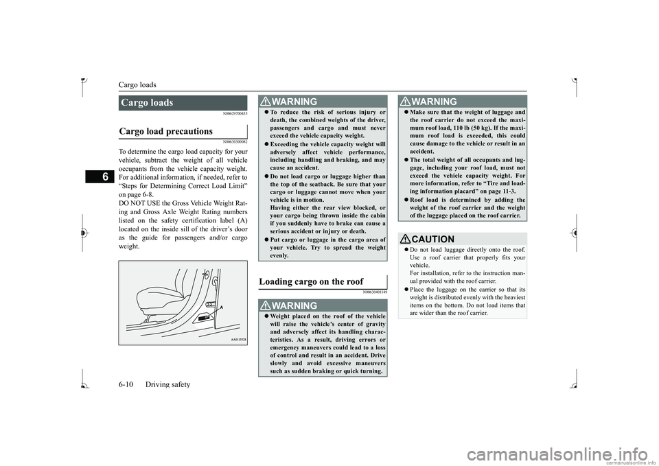
For additional information, if needed, refer to “Steps for Determining Correct Load Limit” on page 6-8. DO NOT USE the Gross Vehicle Weight Rat- ing and Gross Axle Weight Rating numberslisted on the safety certification label (A) as the guide for pass
engers and/or cargo
weight.
N00630401149
Cargo loads Cargo load precautions
WA R N I N G To reduce the risk of serious injury or death, the combined weights of the driver,passengers and cargo and must neverexceed the vehicle capacity weight. Exceeding the vehicle capacity weight will adversely affect ve
hicle performance,
including handling and braking, and may cause an accident. Do not load cargo or luggage higher than the top of the seatback. Be sure that yourcargo or luggage cann
ot move when your
vehicle is in motion. Having either the re
ar view blocked, or
your cargo being thrown
inside the cabin
if you suddenly have to brake can cause a serious accident or
injury or death.
Put cargo or luggage in the cargo area of your vehicle. Try to spread the weightevenly.
Loading cargo on the roof
WA R N I N G Weight placed on the
roof of the vehicle
will raise the vehicle’ and adversely affect
its handling charac-
teristics. As a result, driving errors oremergency maneuvers could lead to a loss of control and result in an accident. Drive slowly and avoid excessive maneuverssuch as sudden brak
ing or quick turning.
Make sure that the
weight of luggage and
the roof carrier do not exceed the maxi-mum roof load, 110 lb (50 kg). If the maxi-mum roof load is ex
ceeded, this could
cause damage to the ve
hicle or result in an
accident. The total weight of all occupants and lug- gage, including your r
oof load, must not
exceed the vehicle capacity weight. For more information, refer to “Tire and load- ing information placard” on page 11-3. Roof load is determined by adding the weight of the roof
carrier and the weight
of the luggage placed
on the roof carrier.
CAUTIONDo not load luggage directly onto the roof. Use a roof carrier that properly fits your vehicle. For installation, refer to the instruction man-ual provided with the roof carrier. Place the luggage on the carrier so that its weight is distri
buted evenly with the heaviest
items on the bottom. Do not load items that are wider than the roof carrier.WA R N I N G
BK0236100US.book 10 ページ 2016年2月1日 月曜日 午前10時15分
Page 192 of 307
Trailer towing
Driving safety 6-11
6
N00629801358
Before driving and after traveling a short dis- tance, always check the load to make sure itis securely fastened to the roof carrier.Stop the vehicle periodi
cally and check that
the load remains secure. If the load is not secure, it could fall from the vehicle anddamage your vehicle,
another vehicle or cre-
ate a road hazard.NOTE
To prevent wind noise or reduction in gas mileage, remove the roof carrier when not in use. Before using an automatic car wash, check with the attendant to determine if the roofcarrier should be removed. Be sure that adequate clearance is main- tained for raising the trunk lid during loading luggage on the roof carrier.CAUTION
Trailer towing
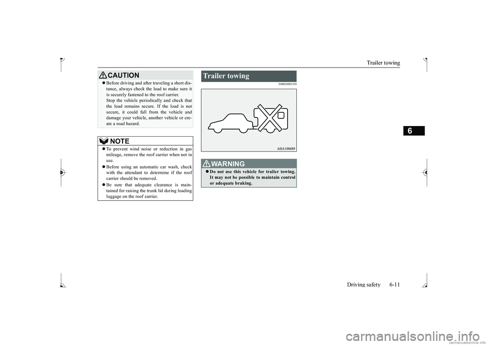
WA R N I N G Do not use this vehicle for trailer towing. It may not be possible to maintain control or adequate braking.
BK0236100US.book 11 ページ 2016年2月1日 月曜日 午前10時15分
Page 193 of 307
BK0236100US.book 12 ページ 2016年2月1日 月曜日 午前10時15分
Page 194 of 307
7
Comfort controlsVents ................................................................................................7-2 Heater without air conditioning functi
on (if so equipped) ...............7-4
Manual air conditioning (if so equipped) .........................................7-7Automatic air conditioning (if so equipped)...................................7-12 Important air conditioning operating tips ..
...........
...........
.........
.....7-18
Air purifier (if so equipped)............................................................7-19AM/FM electronically tune
d radio with CD player
(if so equipped) ..........................................................................7-19 To play tracks from USB device (if so equipped) ..........................7-29 To play tracks from a Bluetooth
® device
(vehicles with Bluetooth
® 2.0 interface) ...................................7-37
Steering wheel audio remote control
switches (if so equipped) .....7-40
Error codes .....................................................................................7-41 Handling of compact discs .............................................................7-42 Antenna ..........................................................................................7-44General information about your radio .....
...........
...........
...........
.....7-44
BK0236100US.book 1 ページ 2016年2月1日 月曜日 午前10時15分
Page 195 of 307
Vents 7-2 Comfort controls
7
N00729901305 N00730200330
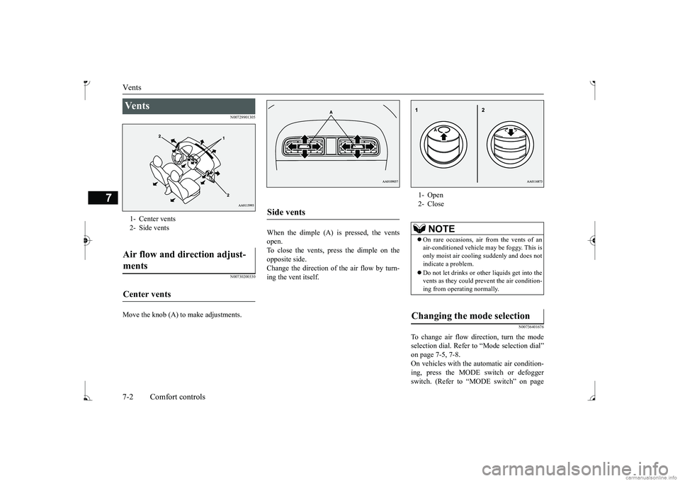
Move the knob (A) to make adjustments.
When the dimple (A) is pressed, the vents open. To close the vents, press the dimple on the opposite side.Change the direction of the air flow by turn- ing the vent itself.
N00736401676
To change air flow di
rection, turn the mode
selection dial. Refer to
“Mode selection dial”
on page 7-5, 7-8. On vehicles with the
automatic air condition-
ing, press the MODE
switch or defogger
switch. (Refer to “MODE switch” on page
Ve n t s 1- Center vents2- Side ventsAir flow and direction adjust- ments Center vents
Side vents
1- Open 2- Close
NOTE
On rare occasions, air from the vents of an air-conditioned vehicle
may be foggy. This is
only moist air cooling suddenly and does not indicate a problem. Do not let drinks or ot
her liquids get into the
vents as they could pr
event the air condition-
ing from operating normally.
Changing the mode selection
BK0236100US.book 2 ページ 2016年2月1日 月曜日 午前10時15分
Page 196 of 307
Vents
Comfort controls 7-3
7
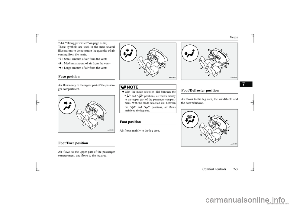
7-14, “Defogger switch” on page 7-14.) These symbols are used in the next severalillustrations to demonstr
ate the quantity of air
coming from the vents. : Small amount of air from the vents : Medium amount of air from the vents : Large amount of air from the vents Air flows only to the upper part of the passen- ger compartment. Air flows to the upper part of the passenger compartment, and flows to the leg area.
Air flows mainly to the leg area.
Air flows to the leg area, the windshield and the door windows.
Face position Foot/Face position
NOTE
With the mode select
ion dial between the
“ ” and “ ” positions, air flows mainly to the upper part of the passenger compart-ment. With the mode se
lection dial between
the “ ” and “ ” positions, air flows mainly to the leg area.
Foot position
Foot/Defroster position
BK0236100US.book 3 ページ 2016年2月1日 月曜日 午前10時15分
Page 197 of 307
Heater without air conditioning function (if so equipped) 7-4 Comfort controls
7
Air flows mainly to the windshield and the door windows.
N00737700031
The heater can only be used while the engineis running.
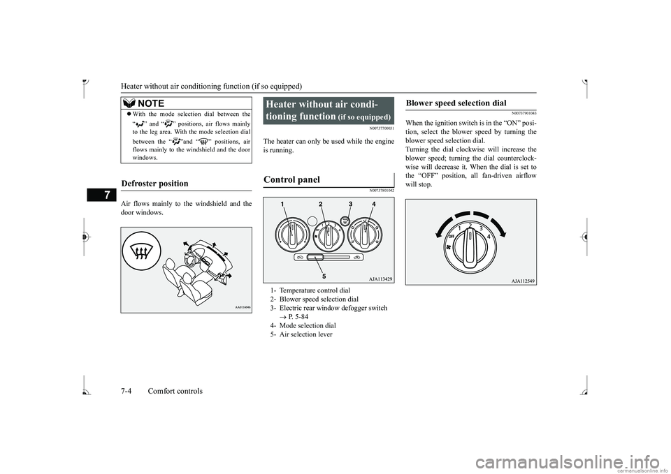
N00737801042
N00737901043
When the ignition switch is in the “ON” posi- tion, select the blower speed by turning the blower speed selection dial.Turning the dial clockwise will increase the blower speed; turning
the dial counterclock-
wise will decrease it. When the dial is set tothe “OFF” position, all fan-driven airflow will stop.
NOTE
With the mode selec
tion dial between the
“ ” and “ ” positions, air flows mainly to the leg area. With the mode selection dial between the “ ”and “ ” positions, air flows mainly to the windshield and the door windows.
Defroster position
Heater without air condi- tioning function
(if so equipped)
1- Temperature control dial 2- Blower speed selection dial 3- Electric rear win
dow defogger switch
P. 5-84
4- Mode selection dial 5- Air selection lever
Blower speed selection dial
BK0236100US.book 4 ページ 2016年2月1日 月曜日 午前10時15分
Page 198 of 307
Heater without air conditioning function (if so equipped)
Comfort controls 7-5
7
N00738001067
Turn the temperature c
ontrol dial clockwise
to make the air warmer
. Turn it counterclock-
wise to make the air cooler.
N00738101084
To change air flow di
rection, turn the mode
selection dial. Refer
to “Changing the mode
selection” on page 7-2.
N00738201056
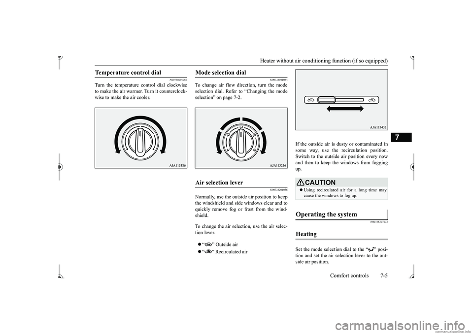
Normally, use the outside air position to keepthe windshield and side
windows clear and to
quickly remove fog or frost from the wind- shield. To change the air selection, use the air selec- tion lever. “ ” Outside air “ ” Recirculated air
If the outside air is dusty or contaminated in some way, use the recirculation position. Switch to the outside
air position every now
and then to keep the windows from fogging up.
N00738301073
Set the mode selection
dial to the “ ” posi-
tion and set the air selection lever to the out- side air position.
Temperature control dial
Mode selection dial
Air selection lever
CAUTION Using recirculated ai
r for a long time may
cause the windows to fog up.
Operating the system
Heating
BK0236100US.book 5 ページ 2016年2月1日 月曜日 午前10時15分
Page 199 of 307
Heater without air conditioning function (if so equipped) 7-6 Comfort controls
7
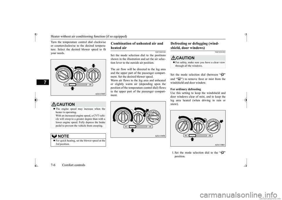
Turn the temperature control dial clockwise or counterclockwise to
the desired tempera-
ture. Select the desire
d blower speed to fit
your needs.
N00738401045
Set the mode selection
dial to the positions
shown in the illustration and set the air selec- tion lever to the outside air position. The air flow will be directed to the leg area and the upper part of the passenger compart-ment. Set the desired blower speed. Warm air flows to the leg area and unheated or slightly warm air (depending upon the position of the temperat
ure control dial) flows
to the upper part of the passenger compart-ment.
N00738501091
Set the mode selection dial (between “ ” windshield and door window. For ordinary defrosting Use this setting to ke
ep the windshield and
door windows clear of mist, and to keep the leg area heated (when driving in rain or snow). 1. Set the mode select
ion dial to the “ ”
CAUTION The engine speed may increase when the heater is operating. With an increased engi
ne speed, a CVT vehi-
cle will creep to a greater degree than with a lower engine speed. Fully depress the brake pedal to prevent the vehicle from creeping.NOTE
For quick heating, set the blower speed at the 3rd position.
Combination of unheated air and heated air
Defrosting or defogging (wind-shield, door windows)
CAUTION For safety, make sure you have a clear view through all the windows.
BK0236100US.book 6 ページ 2016年2月1日 月曜日 午前10時15分
Page 200 of 307
Manual air conditioning (if so equipped)
Comfort controls 7-7
7
2. Set the air selection le
ver to the outside air
position.3. Select your desired
blower speed by turn-
ing the blower spee
d selection dial.
4. Select your desired
temperature by turn-
ing the temperature control dial.
For quick defrosting 1. Set the mode selection dial to the “ ” 2. Set the air selection le
ver to the outside air
position. 3. Set your blower to the maximum speed. 4. Set the temperature to the highest posi-tion.
N00730300344
The air conditioning can only be used whilethe engine is running.
N00730501327
N00736501228
When the ignition switch is in the “ON” posi- tion, select the blower speed by turning the blower speed se
lection dial.
Turning the dial clockwise will increase the blower speed; turning
the dial counterclock-
wise will decrease it. When the dial is set tothe “OFF” position, all fan-driven airflow will stop.
NOTE
To defog quickly, direct the air flow from the side vents toward the door windows.
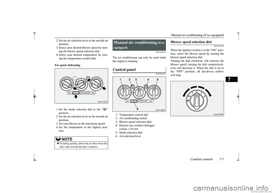
Manual air conditioning
(if so
equipped)
1- Temperature control dial 2- Air conditioning switch 3- Blower speed selection dial 4- Electric rear window defogger
switch
P.5-84
5- Mode selection dial 6- Air selection lever
Blower speed selection dial
BK0236100US.book 7 ページ 2016年2月1日 月曜日 午前10時15分