wheel MITSUBISHI MIRAGE G4 2019 (in English) Owner's Guide
[x] Cancel search | Manufacturer: MITSUBISHI, Model Year: 2019, Model line: MIRAGE G4, Model: MITSUBISHI MIRAGE G4 2019Pages: 267, PDF Size: 38.31 MB
Page 127 of 267
Rear-view camera 5-62 Features and controls
5
N00532900153
If new wheels with new tire inflation pressure sensors are installed, their ID codes must be programmed into the tire pressure monitoring system. Have tire and wheel replacement per-formed by an authorized Mitsubishi Motors dealer to avoid the ri
sk of damaging the tire
inflation pressure sensors. If the wheelreplacement is not done by an authorized Mitsubishi Motors dealer
, it is not covered by
your warranty.
N00533000236
Your tire pressure monitoring system oper- ates on a radio frequency subject to Federal Communications Comm
ission (FCC) Rules
(For vehicles sold in U.S.A.) and Industry Canada Rules (For vehicles sold in Canada). This device complies with part 15 of FCCRules and Industry Ca
nada licence-exempt
RSS standard(s). Operation is subject to the following two con- ditions. This device may not
cause harmful inter-
ference This device must ac
cept any interference
received, including interference that may cause undesired operation.
N00546201385
When the gearshift lever or the selector leveris in the “R” position with the ignition switch or the operation mode is in ON, the rear-view
image will be displayed
on the screen of the
DISPLAY AUDIO or the Smartphone LinkDisplay Audio. When the gearshift lever or the selector lever is shifted out of the “R” position, the rear-view image will go off.
NOTE
Tire inflation pressures vary with the ambi- ent temperature. If the
vehicle is subjected to
large variations in am
bient temperature, the
tire inflation pressures may be under-inflated (causing the warning light come on) when the ambient temperature is relatively low. Ifthe warning light comes on, adjust the tire inflation pressure.
Whenever the tires and wheels are replaced with new ones
CAUTION The use of non-genuine wheels will prevent the proper fit of the tire inflation pressure sensors, resulting air
leakage or damage of
the sensors.
General information
WA R N I N G Changes or modifica
tions not expressly
approved by the manufacturer for compli- ance could void the
user’s authority to
operate the equipment.
Rear-view camera
WA R N I N G Never rely solely on the rear-view camera to clear the area behind your vehicle.Always check visua
lly behind and all
around your vehicle fo
r persons, animals,
obstructions or other vehicles. Failure todo so can result in
vehicle damage, serious
injury or death. The rear-view camera is an aid system for backing up, but it is not a substitute for your visual confirmation. The view on the scre
en is limited, and
objects outside the view, such as under thebumper or around either corner of the bumper, cannot be seen on the screen.
BK0267800US.book 62 ページ 2018年5月30日 水曜日 午後4時24分
Page 146 of 267
Turn signal lever
Features and controls 5-81
5
the light switch to the “OFF” position to stop the tone.
N00549900142
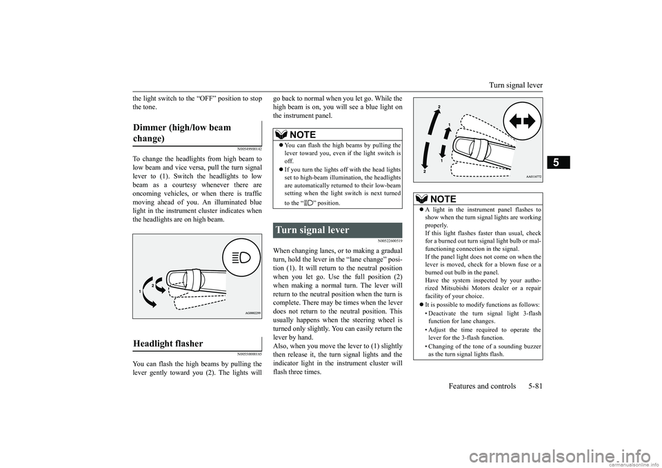
To change the headlights from high beam tolow beam and vice vers
a, pull the turn signal
lever to (1). Switch the headlights to low beam as a courtesy whenever there are oncoming vehicles, or when there is traffic moving ahead of you. An illuminated bluelight in the instrument
cluster i
ndicates when
the headlights are on high beam.
N00550000185
You can flash the high beams by pulling the lever gently toward you (2). The lights will
go back to normal when you let go. While the high beam is on, you will
see a blue light on
the instrument panel.
N00522600519
When changing lanes, or
to making a gradual
turn, hold the lever in the “lane change” posi- tion (1). It will return
to the neutral position
when you let go. Use the full position (2) when making a normal turn. The lever will return to the neutral position when the turn iscomplete. There may be times when the lever does not return to the neutral position. This usually happens when the steering wheel isturned only slightly. You
can easily return the
lever by hand. Also, when you move the lever to (1) slightlythen release it, the turn signal lights and the indicator light in the instrument cluster will flash three times.
Dimmer (high/low beam change) Headlight flasher
NOTE
You can flash the high beams by pulling the lever toward you, even if the light switch isoff. If you turn the lights off with the head lights set to high-beam illumin
ation, the headlights
are automatically returned to their low-beam setting when the light
switch is next turned
to the “ ” position.
Turn signal lever
NOTE
A light in the instrument panel flashes to show when the turn signal lights are workingproperly. If this light flashes fa
ster than usual, check
for a burned out turn signal light bulb or mal-functioning connection in the signal. If the panel light does not come on when the lever is moved, check for a blown fuse or aburned out bulb in the panel. Have the system inspected by your autho- rized Mitsubishi Motors dealer or a repairfacility of your choice. It is possible to modi
fy functions as follows:
• Deactivate the turn signal light 3-flash function for lane changes. • Adjust the time required to operate the lever for the 3-flash function. • Changing of the tone of a sounding buzzer as the turn signal lights flash.
BK0267800US.book 81 ページ 2018年5月30日 水曜日 午後4時24分
Page 150 of 267
Horn switch
Features and controls 5-85
5
N00523800185
To honk the horn, press around the “ ” mark on the steering wheel.
N00563701196
The Link System takes co
ntrol of the devices
connected via the USB input terminal or the Bluetooth
®; the system allows the connected
devices to be operated by using the switches in the vehicle or voice commands (if so equipped).For details on how to operate, refer to “USB input terminal” on page 5-85 and the separate owner’s manual. Bluetooth
® is a registered trademark of
BLUETOOTH SIG, INC.
N00566701171
You can connect your USB memory device or iPod
* to play music files stored in the USB
memory device or iPod.This section explains
how to connect and
remove a USB memory device or iPod. Refer to the separate owner’s manual fordetails on the types of
connectable devices
and supported files, a
nd how to play music
files. * : “iPod” is a registered trademark of Apple Inc. in the United States and other countries.
CAUTION The rear window defogge
r is not designed to
melt snow. Remove
any snow manually
before using the rear window defogger. Use the rear window de
fogger only after the
engine has started and
is running. Be sure to
turn the defogger swit
ch off immediately
after the window is cl
ear to save on battery
power. Do not place stickers,
tape, or other items
that are attached with adhesive over the gridwires on the rear window. When cleaning the inside
rear window, use a
soft cloth and wipe lightly over the grid wires.NOTE
If your vehicle is equi
pped with heated mir-
rors, mist can also be removed from the out-side rearview mirrors when the rear window defogger switch is pressed. (Refer to “Door mirror heater” on page 5-37.)
Horn switch
Link System
(if so equipped)
USB input terminal
WA R N I N G Do not perform to connect/disconnect the USB memory device or iPod while driving.This can be dangerous. Be sure to perform before driving.
BK0267800US.book 85 ページ 2018年5月30日 水曜日 午後4時24分
Page 164 of 267
Vehicle preparatio
n before driving
Driving safety 6-3
6
N00629001770
For a safer and more enjoyable trip, always check for the following:
Before starting the ve
hicle, make certain
that you and all passengers are seated and wearing their seat belts properly (with children in the rear seat, in appropriaterestraints), and that all the doors are locked. Move the driver’s seat as far backward as possible, while keeping good visibility, and good control of the steering wheel, brakes, accelerator, and controls. Check the instrument panel indicators and multi- information display for any possible prob-lem. Similarly, the front
passenger seat should
also be moved as fa
r back as possible.
Make sure that infants and small children are properly restrained in accordance with all laws and regulations.
Check these by selectin
g the defroster mode,
and set the blower switch on high. You shouldbe able to feel the air blowing against the windshield. Refer to “Defrosti
ng or defogging (wind-
shield, door windows)” on page 7-6, 7-10, 7-17.
NOTE
The shape of the mat and the number of retaining clips may
vary depending on the
vehicle model.WA R N I N G If a floor mat is the
wrong size or is not
properly installed, it can interfere with the operation of the pedals. Interference with the pedals can cause unintended accelera-tion and/or increase
d stopping distances
resulting in a cras
h and injury. Always
make sure the floor mat does not interferewith the accelerator or brake pedal. Always use the retaining clip on the driver’s floorboard to secure the floor mat. Always install the mat with the correct side facing down. Never install a second mat over or under an existing floor mat. Do not use a floor mat designed for another model vehicle even if it is a Mitsubishi Motors Genuine floor mat. Before driving, be sure to check the fol- lowing:• Periodically check that the floor mat is properly secured with the retaining clips. If you remove the fl
oor mat while clean-
ing the inside of you
r vehicle or for any
other reason, always
check the condition
of the floor mat afte
r it has been rein-
stalled.
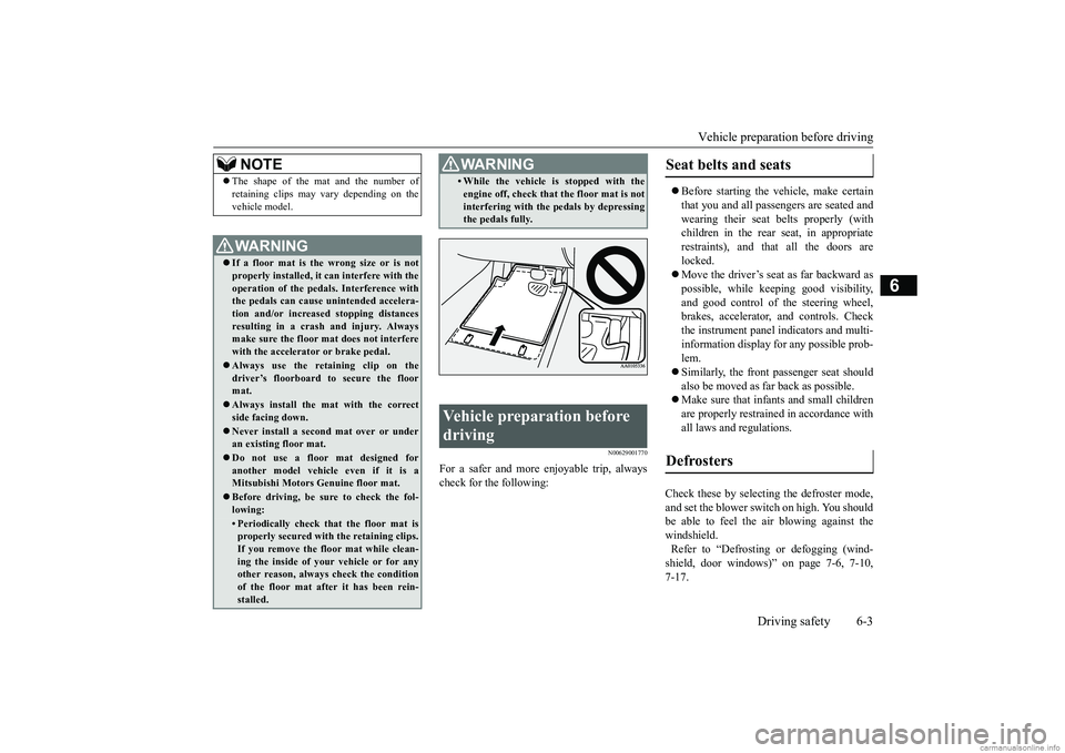
• While the vehicle is stopped with theengine off, check that the floor mat is notinterfering with the pedals by depressingthe pedals fully.
Vehicle preparation before driving
WA R N I N G
Seat belts and seats Defrosters
BK0267800US.book 3 ページ 2018年5月30日 水曜日 午後4時24分
Page 165 of 267
Safe driving techniques 6-4 Driving safety
6
Check all the tires for heavy tread wear or uneven wear patterns.
Look for stones, nails,
glass, or other objects
stuck in the tread. Look
for any tread cuts or sidewall cracks. Check the wheel nuts for tightness, and the tires (including spare tire) for proper pressure.Replace your tires before they are heavily worn out. On vehicles equipped with a tire pressure monitoring system, there
is a risk of damage
to the tire inflation pressure sensors when thetire is replaced on the
rim. Tire replacement
should, only be perform
ed by an authorized
Mitsubishi Motors dealer. Have someone watch while you turn all the exterior lights on and off. Also check the turnsignal indicators and hi
gh-beam indicators on
the instrument panel. Check the ground under the vehicle after parking overnight, for
fuel, water, oil, or
other leaks. Make sure
all the fluid levels are
correct. Also, if you
can smell fuel, you need
to find out why imme
diately and have it
fixed.
N00629200137
Even this vehicle’s safety equipment, andyour safest driving, cannot guarantee that youcan avoid an accident or injury. However, if you give extra attention to the following areas, you can better protect yourself and your passengers: Drive defensively. Be aware of traffic, road and weather c
onditions. Leave plenty
of stopping distance
between your vehicle
and the vehicle ahead. Before changing lanes, check your mir- rors, your blind spots, and use your turn- signal light. While driving, watch the behavior of other drivers, bicycl
ists, and pedestrians.
Always obey applicab
le laws and regula-
tions. Be a polite and alert driver. Alwaysleave room for unexpected events, such as sudden braking. If you plan to drive in another country, obey their vehicle re
gistration laws and
make sure you will be able to get the right fuel.
N00629400474
Check the battery. At the same time, check the terminals and wiring. During extremely cold weather, the battery willnot be as strong. Al
so, the battery power
level may drop because more power is used for cold starting and driving.Before driving the vehicle, check to see if the engine runs at the proper speed and if the headlights are as bright as normally. Charge or replace the battery if necessary. During extreme cold weather, it is possi-ble that a very low battery could freeze. Warm the engine sufficiently. After start- ing the engine, allow a short warm-uptime to distribute oil to all cylinders. Then drive your vehicle slowly. Stay at low speeds at first so that the man- ual transaxle oil or the automatic transaxle fluid has time to spread to all the lubrica- tion points.
Tires Lights Fluid leaks
Safe driving techniques
Driving during cold weather
WA R N I N G The battery gives off explosive hydrogen gas. Any spark or flame can cause the bat- tery to explode, which could cause seriousinjury or death. Always wear protecti
ve clothes and a face
mask when working wi
th your battery, or
let a skilled mechanic do it.
BK0267800US.book 4 ページ 2018年5月30日 水曜日 午後4時24分
Page 166 of 267
Braking
Driving safety 6-5
6
Manual transaxle can be harder to shift in cold weather conditions. This is normaland shifting will get ea
sier as the transaxle
warms up. Check the engine antifreeze. If there is not enough coolant because of a leak or from engine
overheating, add
Mitsubishi Motors Ge
nuine Super Long
Life Coolant Premium or equivalent. Please read this section in conjunction with the “Engine coolant” on page 9-7.
N00629500521
All parts of the brake system are critical to safety. Have the vehicle serviced by an autho- rized Mitsubishi Motors dealer or a repairfacility of your choice at regular intervals according to the “WARRANTY AND MAINTENANCE MANUAL”. Check the brake system while driving at a low speed immediately
after starting, espe-
cially when the brakes are wet, to confirm they work normally.A film of water can be formed on the brake discs or brake drums, and prevent normal braking after driving in heavy rain or throughlarge puddles, or after the vehicle is washed. If this occurs, dry the brakes out by driving slowly while lightly depressing the brakepedal. On snowy roads, ice can form on the braking system, making the brak
es less effective.
While driving in such conditions, pay closeattention to surrounding
vehicles and to the
condition of the road surface. From time to time, lightly depress the brake pedal andcheck how effective the brakes are. It is important to take
advantage of the engine
braking by downshifting while driving on steep downhill roads in order to prevent the brakes from overheating.
N00629601372
When parking on a hill, set the parking brake, and turn the front wheels toward the curb on a downhill, or away from the curb on an uphill.If necessary, apply chocks to the wheels. Place the gearshift lever into the “R” (Reverse) position when parking on a down- hill slope, into the 1st position when parking on an uphill slope. Be sure that the parking brake is firmly set when parked and that the selector lever is in the “P” (PARK) position. When parking on a hill, it is important to setthe parking brake before
moving the selector
lever to the “P” (PARK) position. This pre- vents loading the parking brake against the
WA R N I N G Never open the radiator cap when the radiator is hot. You could be seriously burned.
Braking When brakes are wet
When driving in cold weather When driving downhill
Parking Parking on a hill For vehicles equipped with man- ual transaxle For vehicles equipped with contin- uously variable transmission (CVT)
BK0267800US.book 5 ページ 2018年5月30日 水曜日 午後4時24分
Page 167 of 267
Loading information 6-6 Driving safety
6
transaxle. When this ha
ppens, it is difficult to
move the selector lever out of the “P”(PARK) position. Never leave the engine running while you take a short nap or rest. Also, never leave the engine running in a closed or poorly venti- lated place. Your front bumper can be damaged if you scrape it over curbs or parking stop blocks. Be careful when traveling up or down steep slopes where your bumper can scrape theroad.
More effort could be required to turn the steering wheel. Refer to “Electric
power steering system
(EPS)” on page 5-51. Always carry the key and lock all doors when leaving the vehicle unattended. Always try to park your vehicle in a well lit area.
N00629900424
It is very importa
nt to know how much
weight your vehicle can carry. This weight iscalled the vehicle capacity weight and includes the weight of
all occupants, cargo,
non-factory-installed options, if any, beingtowed. The tire and load
ing information plac-
ard located on the driver’s door sill of your vehicle will show how
much weight it may
properly carry. It is important to familiarize yourself with the following terms before
loading your vehicle:
Vehicle maximum load on the tire: load on an individual tire th
at is determined by
distributing to each ax
le its share of the
maximum loaded vehicle weight and dividing by two. Vehicle normal load on the tire: load on an individual tire that is
determined by dis-
tributing to each axle its share of the curb weight, accessory
weight, and normal
occupant weight and dividing by two. Maximum loaded vehicle weight: the sum of -(a) Curb weight; (b) Accessory weight; (c) Vehicle capacity weight; and(d) Production options weight.
Parking with the engine run- ning
WA R N I N G Leaving the engine ru
nning risks injury or
death from accidentally moving the gear-shift lever (manual transaxle) or the selec- tor lever (CVT) or from the accumulation of toxic exhaust fumes in the passengercompartment.
Where you park
WA R N I N G Do not park your vehicle in areas where combustible materials
such as dry grass or
leaves can come in contact with a hotexhaust, since a fire could occur.
Do not keep the steering wheel fully turned for a long time When leaving the vehicle Loading information
WA R N I N G Never overload your ve
hicle. Overloading
can damage your vehicle, adversely affectvehicle performance, including handling and braking, cause tire failure, and result in an accident.
BK0267800US.book 6 ページ 2018年5月30日 水曜日 午後4時24分
Page 197 of 267
If the vehicle breaks down 8-2 For emergencies
8
N00836300233
If your vehicle breaks down on the road, move to the shoulder and turn on the hazard warning flashers. If there is no shoulder, orthe shoulder is not safe, drive in the right lane slowly with the haza
rd lights flashing until
you come to a safe stopping place. Keep theflashers flashing. If the engine stops, there will be no power assist to the steering and brakes, making these difficult to use. The brake booster will not work, so the brakes will not grip well. The brake pedal will be harder to press than usual. Since there is no power steering assist, the steering wheel will be hard to turn.
Get help from your passengers, bystanders, etc. to push the vehicle
and move it to a safe
area.
N00860700058
If the operation mode
cannot be changed to
OFF, perform the following procedure. 1. Move the selector lever to the “P” (PARK) position, and then change the operation mode to OF
F. (For vehicles
with CVT)2. One of the other causes could be low bat- tery voltage. If this occurs, the keyless entry system and the F.A.S.T.-key opera-tion will also not operate. Contact an authorized Mitsubish
i Motors dealer.
N00836401837
If the engine cannot be started because the battery is weak or de
ad, you can start it with
the battery from anothe
r vehicle using jumper
cables.
1. Take off any metal jewelry such as watch bands or bracelets th
at might create an
accidental electrical contact. 2. Position the vehicles close enoughtogether so that the jumper cables can reach, but be sure the vehicles aren’t touching each other.
If the vehicle breaks down If the engine stops/fails When the engine fails at the intersection
If the operation mode can- not be changed to OFF (vehicles equipped with the F.A.S.T.-key) Jump-starting the engine
WA R N I N G To reduce the risk of igniting flammable gas that may be emi
tted from the battery,
carefully read this section before jump-starting the vehicle. Do not try to start you
r vehicle by pushing
or towing. This can cause an accident resulting in serious
injury or death and
can damage the vehicle.NOTE
Do not use jumper cables if they have dam- age or corrosion.CAUTION Check the other vehicle.
It must have a 12-
volt battery. If the other system isn’t 12-volt,both systems can be damaged.
BK0267800US.book 2 ページ 2018年5月30日 水曜日 午後4時24分
Page 200 of 267
Jack and tools
For emergencies 8-5
8
7. If there is no obvious leak source, check the coolant level in th
e engine coolant res-
ervoir. If there is none, or if it is too low, slowly add coolant. 8. If the engine coolant reservoir needs cool-ant, you will probably also need to add coolant to the radiator. Do not loosen or remove the radiator cap until the enginehas cooled down. 9. Start the engine, and slowly add coolant, up to the bottom of the filler neck. Useplain water if you have to (and replace it with the right coolant as soon as possible).
10. Replace the radiator
cap and tighten it
fully. Check the coolant temperature warning light. You can start driving again when the high coolant temperature warn-ing light does not come on.
11. Have the system inspected by your autho-
rized Mitsubishi Motors
dealer or a repair
facility of your choice.
N00836601464
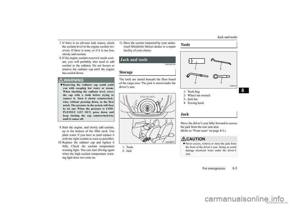
The tools are stored beneath the floor boardof the cargo area. The jack is stored under the driver’s seat.
Move the driver’s seat fully forward to access the jack from the rear seat area.(Refer to “Front seats” on page 4-3.)
WA R N I N G Removing the radiat
or cap could scald
you with escaping hot water or steam. When checking the radiator level, cover the cap with a cloth before trying toremove it. Turn it slowly counterclock- wise, without pressing down, to the first notch. The pressure in the system will thenbe let out. When the pressure is COM- PLETELY LET OUT, press down and keep turning the cap counterclockwiseuntil it comes off.
Jack and tools Storage 1- Tools 2- Jack
Tools 1- Tools bag 2- Wheel nut wrench 3- Jack bar4- Towing hookJack
CAUTION Never access, remove or store the jack from the front of the driver’s seat. Doing so could damage electr
ical wires under the driver’s
seat.
BK0267800US.book 5 ページ 2018年5月30日 水曜日 午後4時24分
Page 202 of 267
How to change a tire
For emergencies 8-7
8
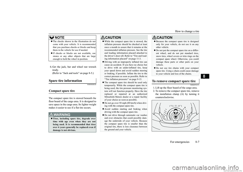
6. Get the jack, bar and wheel nut wrench ready. (Refer to “Jack and t
ools” on page 8-5.)
N00849600344
The compact spare tire is stowed beneath the floor board of the cargo area. It is designed to save space in the cargo area. Its lighter weightmakes it easier to use if a flat tire occurs.
N00849701371
1. Lift up the floor board of the cargo area. 2. To remove the compact spare tire, remove the installation clamp (A) by turning itcounterclockwise.
NOTE
The chocks shown in the illustration do not come with your vehicl
e. It is recommended
that you purchase chocks or blocks and keepthem in the vehicle for use if needed. If chocks or blocks
are not available, use
stones or any other obj
ects that are large
enough to hold the wheel in position.
Spare tire information Compact spare tire
WA R N I N G Tires, including spar
e tire, degrade over
time with age even when they are notbeing used. It is recommended that tires over 6 years generally
be replaced even if
damage is not obvious.
CAUTION While the compact spare tire is stowed, the inflation pressure shoul
d be checked at least
once a month to assure that it remains at therecommended inflation pressure. See the tire and loading informati
on placard attached to
the driver’s door sill. Refer to “Tire and load-ing information placard” on page 11-3. Driving with an imprope
rly inflated tire can
cause an accident. If
you have no choice but
to drive with an under-inflated tire, keep your speed down and av
oid sudden steering
or braking, if possible. Inflate the tire to the correct pressure as soon as possible. Refer to “Tire inflation pressures” on page 9-15. The compact spare tire should be used only temporarily. While th
e compact spare tire is
being used, the tire pr
essure monitoring sys-
tem will not function
properly. Have the tire
replaced or repaired at an authorizedMitsubishi Motors dealer
or a repair facility
of your choice as soon as possible. Do not go over 50 mph (80 km/h) when driv- ing with the compact spare tire. Avoid sudden starting and braking when driving with the compact spare tire. Do not drive through automatic car washes and over obstacles that
could possibly dam-
age the underside of your vehicle. Becausethe compact spare tire is smaller than the original tire, there is less clearance between the ground and your vehicle.
Because the compact spare tire is designed only for your vehicle, do not use it on anyother vehicle. Do not put the compact spare tire on a differ- ent wheel, and do not put standard tires,snow tires, wheel covers
or trim rings on the
compact spare wheel. Otherwise, you could damage these parts or other parts on yourvehicle. Do not use tire chains with your compact spare tire. Using a chain could cause damage to your vehicle and loss of the chains.
To remove compact spare tire
CAUTION
BK0267800US.book 7 ページ 2018年5月30日 水曜日 午後4時24分