heater MITSUBISHI MIRAGE G4 2020 Owner's Manual (in English)
[x] Cancel search | Manufacturer: MITSUBISHI, Model Year: 2020, Model line: MIRAGE G4, Model: MITSUBISHI MIRAGE G4 2020Pages: 253, PDF Size: 36.39 MB
Page 31 of 253

Front seats 4-4 Seat and restraint systems
4
N00402100243
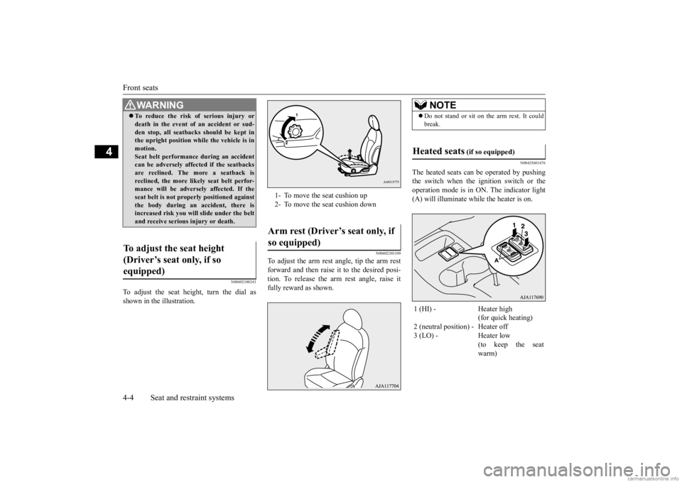
To adjust the seat height, turn the dial as shown in the illustration.
N00402301109
To adjust the arm rest angle, tip the arm rest forward and then raise it to the desired posi- tion. To release the arm rest angle, raise it fully reward as shown.
N00435601476
The heated seats can
be operated by pushing
the switch when the ignition switch or theoperation mode is in ON. The indicator light (A) will illuminate while the heater is on.
WA R N I N G To reduce the risk of serious injury or death in the event of
an accident or sud-
den stop, all seatbacks should be kept inthe upright position while the vehicle is in motion. Seat belt performance during an accidentcan be adversely affect
ed if the seatbacks
are reclined. The more a seatback is reclined, the more likely seat belt perfor-mance will be adversely affected. If the seat belt is not proper
ly positioned against
the body during an accident, there isincreased risk you will slide under the belt and receive serious
injury or death.
To adjust the seat height (Driver’s seat only, if so equipped)
1- To move the seat cushion up 2- To move the seat cushion downArm rest (Driver’s seat only, if so equipped)
NOTE
Do not stand or sit on the arm rest. It could break.
Heated seats
(if so equipped)
1 (HI) - Heater high
(for quick heating)
2 (neutral position) - Heater off 3 (LO) - Heater low
(to keep the seat warm)
BK0284300US.book 4 ページ 2019年5月23日 木曜日 午後12時22分
Page 32 of 253

Rear seat
Seat and restraint systems 4-5
4
N00402501257 N00403001334
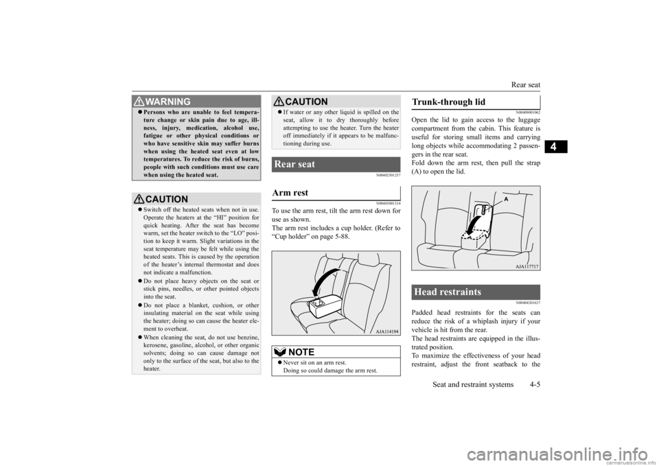
To use the arm rest, tilt the arm rest down for use as shown. The arm rest includes a cup holder. (Refer to“Cup holder” on page 5-88.
N00409001062
Open the lid to gain access to the luggage compartment from the cabin. This feature is useful for storing small items and carryinglong objects while ac
commodating 2 passen-
gers in the rear seat. Fold down the arm rest, then pull the strap(A) to open the lid.
N00404301637
Padded head restraints for the seats can reduce the risk of a whiplash injury if your vehicle is hit from the rear.The head restraints are equipped in the illus- trated position. To maximize the effectiveness of your headrestraint, adjust the front seatback to the
WA R N I N G Persons who are unable to feel tempera- ture change or skin
pain due to age, ill-
ness, injury, medication, alcohol use,fatigue or other phys
ical conditions or
who have sensitive sk
in may suffer burns
when using the heated seat even at lowtemperatures. To reduce the risk of burns, people with such conditions must use care when using the heated seat.CAUTION Switch off the heated seats when not in use. Operate the heaters at the “HI” position for quick heating. After the seat has become warm, set the heater switch to the “LO” posi-tion to keep it warm. Sl
ight variations in the
seat temperature may be felt while using the heated seats. This is caused by the operationof the heater’s internal thermostat and does not indicate
a malfunction.
Do not place heavy objects on the seat or stick pins, needles, or
other pointed objects
into the seat. Do not place a blanket,
cushion, or other
insulating material on the seat while usingthe heater; doing so can
cause the heater ele-
ment to overheat. When cleaning the seat, do not use benzine, kerosene, gasoli
ne, alcohol, or other organic
solvents; doing so can cause damage not only to the surface of the seat, but also to theheater.
If water or any other li
quid is spilled on the
seat, allow it to dry thoroughly beforeattempting to use the heater. Turn the heateroff immediately if it
appears to be malfunc-
tioning during use.
Rear seat Arm rest
NOTE
Never sit on an arm rest. Doing so could damage the arm rest.CAUTION
Trunk-through lid Head restraints
BK0284300US.book 5 ページ 2019年5月23日 木曜日 午後12時22分
Page 162 of 253

Loading information Driving safety 6-7
6
Vehicle normal load on the tire: load on an individual tire that is determined by distributing to each axle its share of the curb weight,accessory weight, and normal occupant weight and dividing by two.Maximum loaded vehicle weight: the sum of - (a) Curb weight;(b) Accessory weight; (c) Vehicle capacity weight; and (d) Production options weight.Curb weight: the weight of a motor vehicle with standard equipment including the maxi-mum capacity of fuel, oil, and coolant.
Accessory weight: the combined weight (in excess of those stan- dard items which may be replaced) of automatic transmis-sion, power steering, power brakes, power windows, power seats, radio, and heater, to theextent that these items are avail- able as factory- installed equip- ment (whether installed or not).Vehicle capacity weight: the rated cargo and luggage load plus 150 lbs (68 kg)
* times the vehicle’s
designated seating capacity.Production options weight: thecombined weight of thoseinstalled regular production options weighing over 5 lbs (2.3 kg) in excess of those standarditems which they
replace, not pre-
viously considered in curb weight or accessory weight, includingheavy duty brakes, ride levelers,roof rack, heavy duty battery, and special trim.
Normal occupant weight: 150 lbs (68 kg)
* times the number of
specified occupants. (In your vehicle the number is 3)Occupant distribution: Occupant distribution within the passenger compartment (In your vehicle thedistribution is 2 in front, 1 in sec- ond row seat) * : 150 lbs (68 kg) is the weight of one person as defined by U.S.A. regulations.
BK0284300US.book 7 ページ 2019年5月23日 木曜日 午後12時22分
Page 173 of 253

Automatic air conditioning 7-6 Comfort controls
7
The above indicates the
factory settings. You
can personalize the air
selection switch and
air conditioning switch to match your per-sonal preferences. Contact your Mitsubishi
Motors dealer or a
repair facility of your choice for assistance.Refer to “Personalizi
ng the air conditioning
switch (Changing the function setting)” on
page7-8. Refer to “Personalizing the air selection(Changing the function setting)” on page7-7.
N00737101247
To change air flow direction, press theMODE switch. Each time the MODE switch is pressed, the mode ch
anges to the next one
in the following sequence: “ ”
“”
“”
“”
“ ”. The selected mode
is shown in the displa
y (A). Refer to “Chang-
ing the mode selection” on page 7-3.
N00703400015
When this switch is pressed, the mode changes to the “ ” mode. The indicator light (A) will come on.
The selected mode is
shown in the display (B). Refer to “Changing the mode selection” on page 7-3.
N00737200368
Normally, use the outside air position to keepthe windshield and side windows clear and toquickly remove fog or frost from the wind- shield. To change the air selection, simply press the air selection switch.
While the engine coolant temperature is low, the temperature of the air from the heaterwill be cool/cold until
the engine warms up,
even if you have selected warm air with the switch. To prevent the windshield and windows fromfogging up, the vent mode
will be changed to
“ ” and the blower sp
eed will be reduced.
When the temperature is set to the highest or the lowest setting under the AUTO opera- tion, the air selection
and the air conditioning
will be automatically changed as follows. • Quick Heating (When th
e temperature is set
to the highest setting) Outside air will be introduced and the air conditioning will stop.If the air selection
and the air conditioning
are operated ma
nually after an automatic
changeover, manual
operation will be
selected. • Quick Cooling (When th
e temperature is set
to the lowest setting) Inside air will be recirculated and the air conditioning wi
ll operate.
NOTE
MODE switch Defogger switch
NOTE
When the defogger switch is pressed, the air conditioning system au
tomatically operates
and outside air (as oppos
ed to recirculated
air) is selected. Refer to “Defrosting or defogging (wind- shield, door windows)” on page 7-9.
Air selection switch
BK0284300US.book 6 ページ 2019年5月23日 木曜日 午後12時22分
Page 222 of 253

Fuses
Vehicle care and maintenance 9-25
9
N00954801342
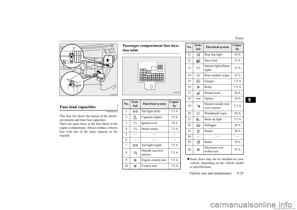
This fuse list shows the names of the electri- cal systems and their fuse capacities. There are spare fuses in the fuse block in theengine compartment. Al
ways replace a blown
fuse with one of the same capacity as the original.
Some fuses may not be installed on your vehicle, depending on
the vehicle model
or specifications.
Fuse load capacities
Type A
Type B
Passenger compartment fuse loca- tion table No.
Sym- bol
Electrical system
Capac-ity
1 Tail light (left) 7.5 A 2 Cigarette lighter 15 A3 Ignition coil 10 A 4 Starter motor 7.5 A 5— — — 6— — — 7 Tail light (right) 7.5 A 8
Outside rearview mirrors
7.5 A
9 Engine control unit 7.5 A 10 Control unit 7.5 A
11 Rear fog light 10 A12 Door lock 15 A 13
Interior light (Dome light)
15 A
14 Rear window wiper 15 A 15 Gauges 7.5 A16 Relay 7.5 A 17 Heated seats 20 A 18 Option 10 A 19
Heated outside rear- view mirrors
7.5 A
20 Windshield wiper 20 A 21 Back-up light 7.5 A22 Defogger 30 A 23 Heater 30 A 24 — — — 25 Radio 10 A 26
Electronic con- trolled unit
15 A
No.
Sym- bol
Electrical system
Capac-ity
BK0284300US.book 25 ページ 2019年5月23日 木曜日 午後12時22分
Page 224 of 253

Fuses
Vehicle care and maintenance 9-27
9
* : Fusible link Some fuses may not be installed on your vehicle, depending on
the vehicle model
or specifications. The table above show
s the main equip-
ment corresponding to each fuse.
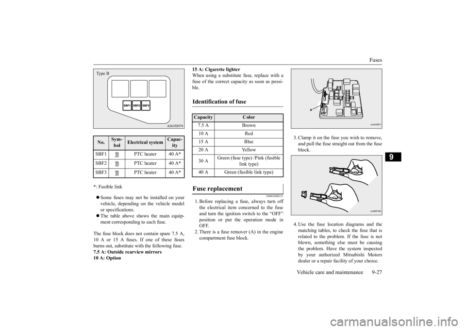
The fuse block does not contain spare 7.5 A, 10 A or 15 A fuses. If one of these fuses burns out, substitute with the following fuse. 7.5 A: Outside rearview mirrors10 A: Option
15 A: Cigarette lighter When using a substitute fuse, replace with afuse of the correct capacity as soon as possi- ble.
N00954900131
1. Before replacing a fuse, always turn off the electrical item concerned to the fuseand turn the ignition switch to the “OFF” position or put th
e operation mode in
OFF.2. There is a fuse remover (A) in the engine compartment fuse block.
3. Clamp it on the fuse you wish to remove, and pull the fuse straight out from the fuseblock. 4. Use the fuse location diagrams and the matching tables, to check the fuse that is related to the problem. If the fuse is notblown, something else must be causing the problem. Have the system inspected by your authorized Mitsubishi Motors dealer or a repair facility of your choice.
No.
Sym- bol
Electrical system
Capac-ity
SBF1 PTC heater 40 A
*
SBF2 PTC heater 40 A
*
SBF3 PTC heater 40 A
*
Type B
Identification of fuse Capacity
Color
7.5 A Brown 10 A Red 15 A Blue 20 A Yellow 30 A
Green (fuse type) /Pink (fusible
link type)
40 A Green (fusible link type)
Fuse replacement
BK0284300US.book 27 ページ 2019年5月23日 木曜日 午後12時22分