Turn signal MITSUBISHI MONTERO 1987 1.G User Guide
[x] Cancel search | Manufacturer: MITSUBISHI, Model Year: 1987, Model line: MONTERO, Model: MITSUBISHI MONTERO 1987 1.GPages: 284, PDF Size: 14.74 MB
Page 90 of 284
WIRING HARNESS - Centralized Junction
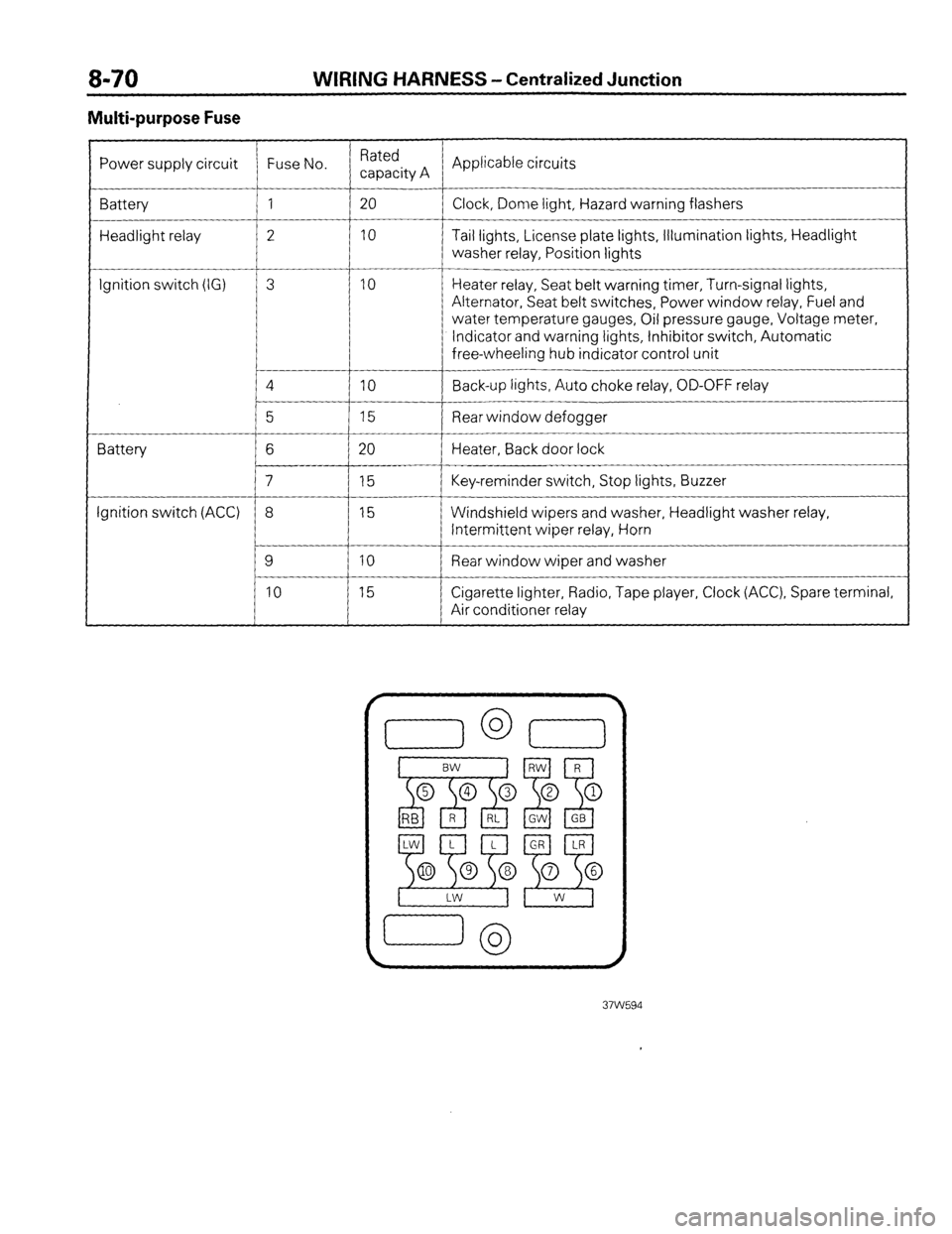
Multi-purpose Fuse
Power supply circuit Fuse No. Rated
capacity A Applicable circuits
Battery 1 20
Clock, Dome light, Hazard warning flashers
Headlight relay 2 10 Tail lights, License plate lights, Illumination lights, Headlight
washer relay, Position lights
__-
Ignition switch (IG) 3 10 Heater relay, Seat belt warning timer, Turn-signal lights,
Alternator, Seat belt switches, Power window relay, Fuel and
water temperature gauges, Oil pressure gauge, Voltage meter,
Indicator and warning lights, Inhibitor switch, Automatic
free-wheeling hub indicator control unit
4
IO Back-up lights, Auto choke relay, OD-OFF relay
__-
5 15 Rear window defogger
Battery 6 20 Heater, Back door lock
7 15 Key-reminder switch, Stop lights, Buzzer
Ignition switch (ACC) 8 15 Windshield wipers and washer, Headlight washer relay,
Intermittent wiper relay, Horn
9 10 Rear window wiper and washer
10 15 Cigarette lighter, Radio, Tape player, Clock (ACC), Spare terminal,
Air conditioner relay
Page 96 of 284
![MITSUBISHI MONTERO 1987 1.G User Guide 8-76 CHARGING SYSTEM - Circuit Diagram
3 CHARGING CIRCUIT
Battery Ignition switch
OFF
Main
m fusible ’ L
link
A-02
fl.3-Br 1~5~~
, A-23 Sub fusible link
(IGN . SW)
IAM IG ] c-55
3
3
A MITSUBISHI MONTERO 1987 1.G User Guide 8-76 CHARGING SYSTEM - Circuit Diagram
3 CHARGING CIRCUIT
Battery Ignition switch
OFF
Main
m fusible ’ L
link
A-02
fl.3-Br 1~5~~
, A-23 Sub fusible link
(IGN . SW)
IAM IG ] c-55
3
3
A](/img/19/7559/w960_7559-95.png)
8-76 CHARGING SYSTEM - Circuit Diagram
3 CHARGING CIRCUIT
Battery Ignition switch
OFF
Main
m fusible ’ L
link
A-02
fl.3-Br 1~5~~
, A-23 Sub fusible link
(IGN . SW)
IAM IG ] c-55
3
3
A m
A
To turn signal flasher
unit [Refer to P.8-49.1 Multi-
n, Irnn4P
ComSeter
Remark
For information concerning the ground points (example:
q ),
refer to P.8-7. 37W605
Wiring color code
B: Black Br: Brown G: Green Gr: Gray L: Blue Lg: Light green
LI: Light blue 0: Orange P: Pink R: Red Y: Yellow W: White
1 STB Revision
Page 101 of 284
CHARGING SYSTEM - Service Adjustment Procedures 8-81
(2) Upon completion of the test, set the engine speed at idle and
turn off the ignition switch.
(3) Disconnect the battery ground cable.
(4) Remove the test voltmeter and ammeter and the engine ta-
chometer.
(5) Connect the alternator output wire to the alternator “B” ter-
minal.
(6) Connect the battery ground cable.
ll3Y1848 2. Remove battery from vehicle.
Caution
White
I Blue
I Care should be taken in the event battery case is cracked
or leaking to protect hands from the electrolyte. A suit-
able pair of rubber gloves (not the household type) should
be worn when removing battery by hand.
3. Inspect battery carrier for damage caused by loss of acid from
battery. If acid damage is present, it will be necessary to clean
area with a solution of clean warm water and baking soda.
Scrub area with a stiff bristle brush and wipe off with a cloth
moistened with ammonia or baking soda in water.
4. Clean top of battery with same solutions as described in Step
(3).
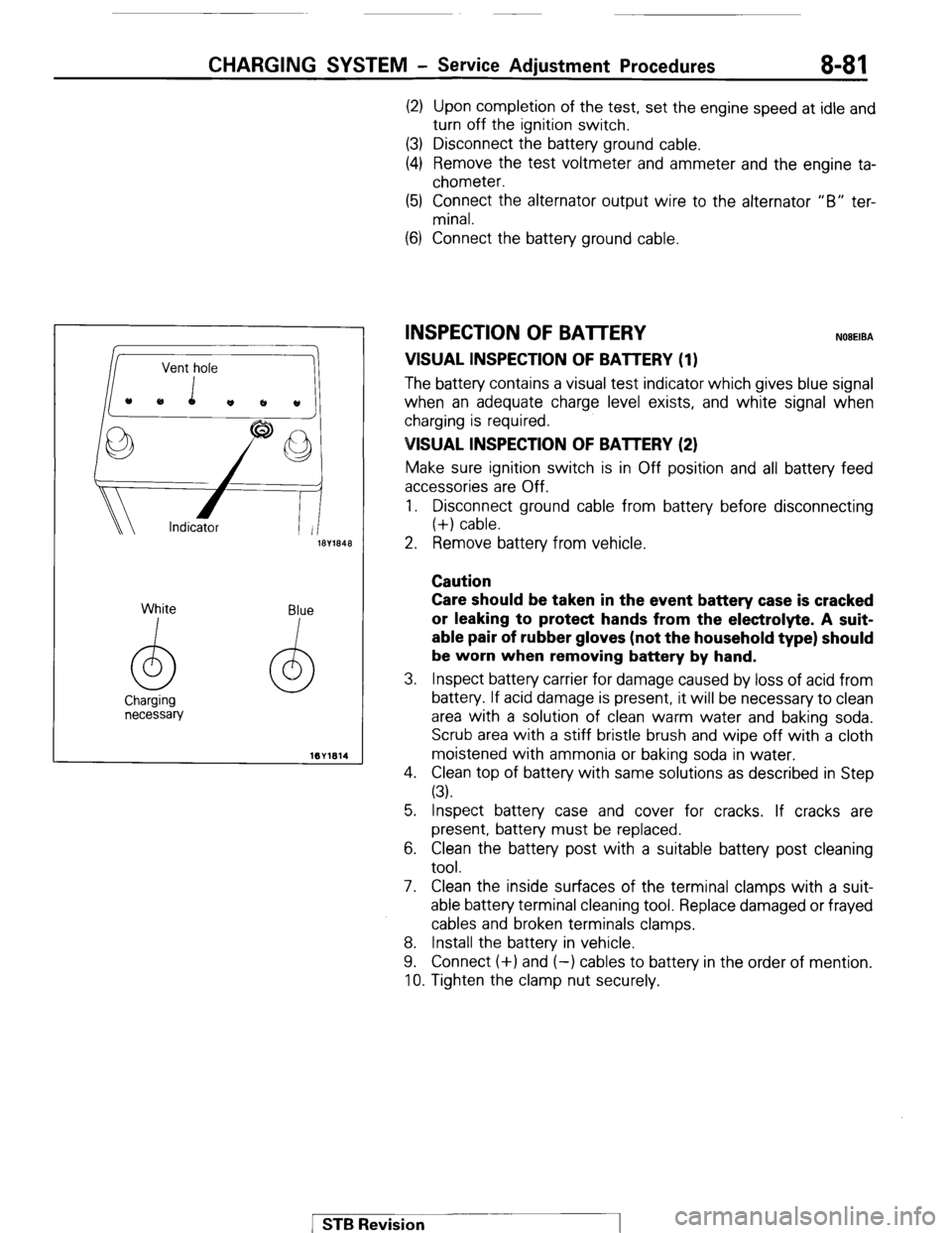
INSPECTION OF BATTERY NOBEIBA
VISUAL INSPECTION OF BATTERY (1)
The batten/ contains a visual test indicator which gives blue signal
when an adequate charge level exists, and white signal when
charging is required.
VISUAL INSPECTION OF BAlTERY (2)
Make sure ignition switch is in Off position and all battery feed
accessories are Off.
1. Disconnect ground cable from battery before disconnecting
(+) cable.
5. Inspect battery case and cover for cracks. If cracks are
present, battery must be replaced.
6. Clean the battery post with a suitable battery post cleaning
tool.
7. Clean the inside surfaces of the terminal clamps with a suit-
able battery terminal cleaning tool. Replace damaged or frayed
cables and broken terminals clamps.
8. Install the battery in vehicle.
9. Connect (+) and (-) cables to battery in the order of mention.
10. Tighten the clamp nut securely.
1 STB Revision
Page 133 of 284
IGNITION SYSTEM-Service Adjustment Procedures 8-113
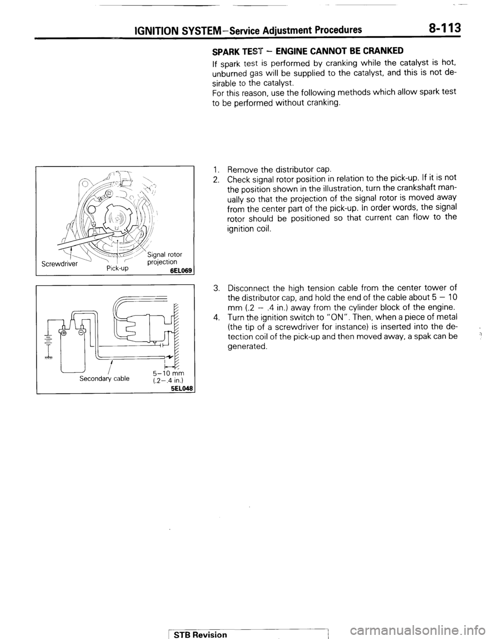
SPARK TEST - ENGINE CANNOT BE CRANKED
If spark test is performed by cranking while the catalyst is hot,
unburned gas will be supplied to the catalyst, and this is not de-
sirable to the catalyst.
For this reason, use the following methods which allow spark test
to be performed without cranking.
1. Remove the distributor cap.
2. Check signal rotor position in relation to the pick-up. If it is not
the position shown in the illustration, turn the crankshaft man-
ually so that the projection of the signal rotor is moved away
from the center part of the pick-up. In order words, the signal
rotor should be positioned so that current can flow to the
ignition coil.
3. Disconnect the high tension cable from the center tower of
the distributor cap, and hold the end of the cable about 5 - 10
mm (.2 - .4 in.) away from the cylinder block of the engine.
4. Turn the ignition switch to “ON”. Then, when a piece of metal
(the tip of a screwdriver for instance) is inserted into the de-
tection coil of the pick-up and then moved away, a spak can be
generated.
+
!:’
Secondary cable 5-10 km
(.2-.4 in.)
5EL0
1 STB Revision
Page 143 of 284
METERS AND GAUGES-Specifications
METERS AND GAUGES
8-123
SPECIFICATIONS
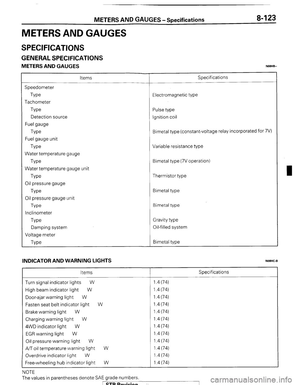
GENERAL SPECIFICATIONS
METERS AND GAUGES NOEHB-
Items
Speedometer
Type
Tachometer
Type
Detection source
Fuel gauge
Type
Fuel gauge unit
Type
Water temperature gauge
Type
Water temperature gauge unit
Type
Oil pressure gauge
Type
Oil pressure gauge unit
Type
Inclinometer
Type
Damping system
Voltage meter
Type Specifications
Electromagnetic type
Pulse type
Ignition coil
Bimetal type (constant-voltage relay incorporated for 7V)
Variable resistance type
Bimetal type (7V operation)
Thermistor type
Bimetal type
Bimetal type
Gravity type
Oil-filled system
Bimetal type
INDICATOR AND WARNING LIGHTS
NOEHC-B
Items Specifications
Turn signal indicator lights
W 1.4 (74)
High beam indicator light W 1.4 (74)
Door-ajar warning light W 1.4 (74)
Fasten seat belt indicator light W 1.4 (74)
Brake warning light W 1.4 (74)
Charging warning light W 1.4 (74)
4WD indicator light W 1.4 (74)
EGR warning light W 1.4 (74)
Oil pressure warning light W 1.4 (74)
A/T oil temperature warning light
W 1.4 (74)
Overdrive indicator light
W 1.4 (74)
Free-wheeling hub indicator light W 1.4 (74)
NOTE
The values in parentheses denote SAE grade numbers.
1 STB Revision ”
Page 148 of 284
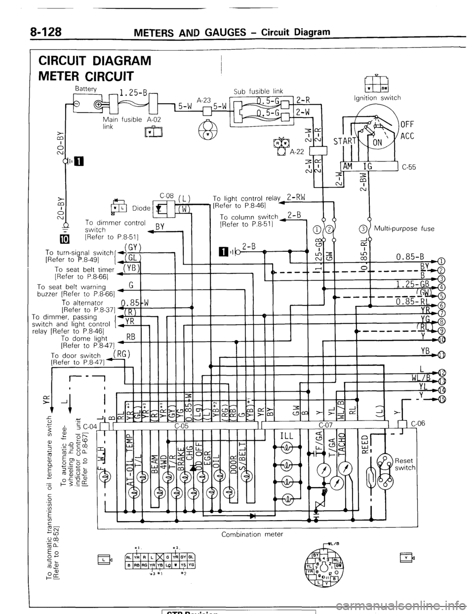
8-128 METERS AND GAUGES - Circuit Diagram
CIRCUIT DIAGRAM
METER CIRCUIT
Ignition switch
q [Refer to
To turn-signal switch
[Refer to P.8-491
I
To seat belt timer
[Refer to P.8-661 P.8-511 -
To seat belt warning
buzzer [Refer to P.8-661
1.25-GBA
, ^.
To alternator 48,5!W III -1 / 1 , 1 '----f--d+ii$$j IRefer to P.8.371 D I
.I_ -0 dimmkr, passinq
‘I+,:’ ! I I I II -I
I r I I I II YI
;witch and light control y K
clay [Refer to P.8-461
To dome liaht 5--hIIII I
----m-w-
[Refer to P&47] -w
Combination meter
( STB Revision
Page 161 of 284
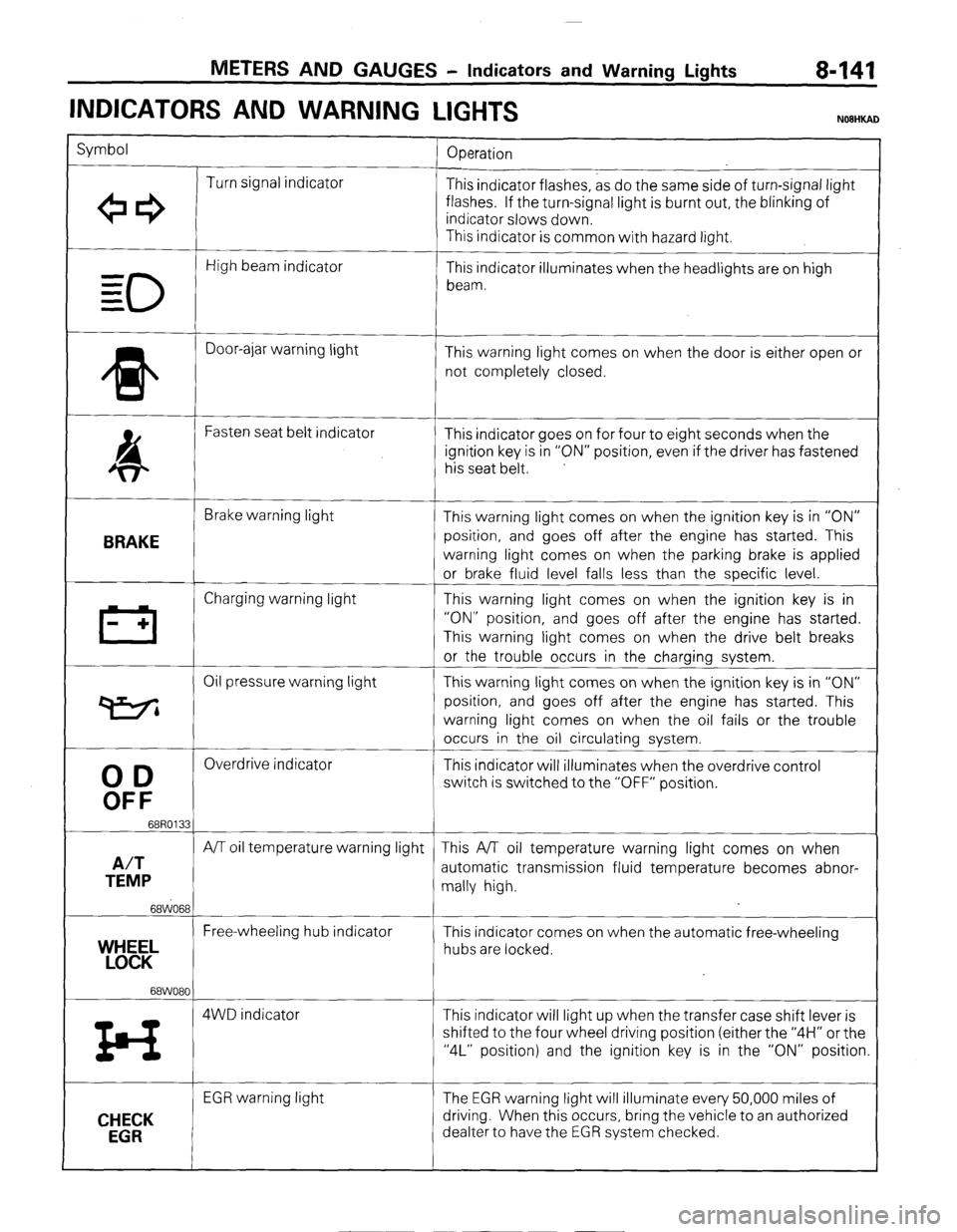
METERS AND GAUGES - Indicators and Warning Lights 8-141
INDICATORS AND WARNING
LIGHTS
Symbol
Operation
Turn signal indicator
+e3 This indicator flashes, as do the same side of turn-signal light
flashes. If the turn-signal light is burnt out, the blinking of
indicator slows down.
This indicator is common with hazard light.
0
High beam indicator
- This indicator illuminates when the headlights are on high
= beam.
=
* Door-ajar warning light
This warning light comes on when the door is either open or
not completely closed.
4 Fasten seat belt indicator
This indicator goes on for four to eight seconds when the
ignition key is in “ON” position, even if the driver has fastened
his seat belt.
BRAKE
Brake warning light
This warning light comes on when the ignition key is in “ON”
position, and goes off after the engine has started. This
warning light comes on when the parking brake is applied
or brake fluid level falls less than the specific level.
III Charging warning light This warning light comes on when the ignition key is in
- + “ON” position, and goes off after the engine has started.
This warning light comes on when the drive belt breaks
or the trouble occurs in the charging system.
Oil pressure warning light This warning light comes on when the ignition key is in “ON”
P position, and goes off after the engine has started. This
warning light comes on when the oil fails or the trouble
occurs in the oil circulating system.
00
Overdrive indicator
This indicator will illuminates when the overdrive control
OFF
switch is switched to the “OFF” position.
68R0133
A/T
A/T oil temperature warning light This A/T oil temperature warning light comes on when
TEMP automatic transmission fluid temperature becomes abnor-
mally high.
68WO68
Free-wheeling hub indicator
YEL This indicator comes on when the automatic free-wheeling
hubs are locked.
68WO80
z4 4WD indicator This indicator will light up when the transfer case shift lever is
shifted to the four wheel driving position (either the “4H” or the
“4L” position) and the ignition key is in the “ON” position.
CHECK
EGR
EGR warning light The EGR warning light will illuminate every 50,000 miles of
driving. When this occurs, bring the vehicle to an authorized
dealter to have the EGR system checked.
) STB Revision
Page 163 of 284
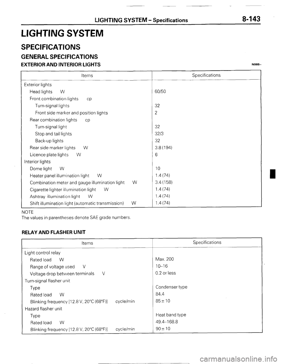
LIGHTING SYSTEM - Specifications 8-143
LIGHTING SYSTEM
SPECIFICATIONS
GENERAL SPECIFICATIONS
EXTERIOR AND INTERIOR LIGHTS NOEIB-
Items
Exterior lights
Head lights W
Front combination lights cp
Turn-signal lights
Front side marker and position lights
Rear combination lights cp
Turn-signal light
Stop and tail lights
Back-up lights
Rear side marker lights W
Licence plate lights W
Interior lights
Dome light W
Heater panel illumination light W
Combination meter and gauge illumination light
Cigarette lighter illumination light
W
Ashtray illumination light
W
Shift illumination light (automatic transmission) W
W
NOTE
The values in parentheses denote SAE grade numbers.
RELAY AND FLASHER UNIT
Items
Light control relay
Rated load W
Range of voltage used V
Voltage drop between terminals V
Turn-signal flasher unit
Type
Rated load W
Blinking frequency [I 2.8 V, 20°C (68”F)l
Hazard flasher unit
Type cycle/min
Rated load W
Blinking frequency [ 12.8 V, 20°C (68”F)l cycle/min Specifications
60/50
32
2
32
32/3
32
3.8(194)
6
10 1.4 (74)
3.4 (158)
1.4 (74)
1.4 (74)
1.4 (74)
Specifications
Max. 200
IO-16
0.2 or less
Condenser type
84.4
85210
Heat band type
49.4-168.8
902 10
1 STB Revision
Page 164 of 284
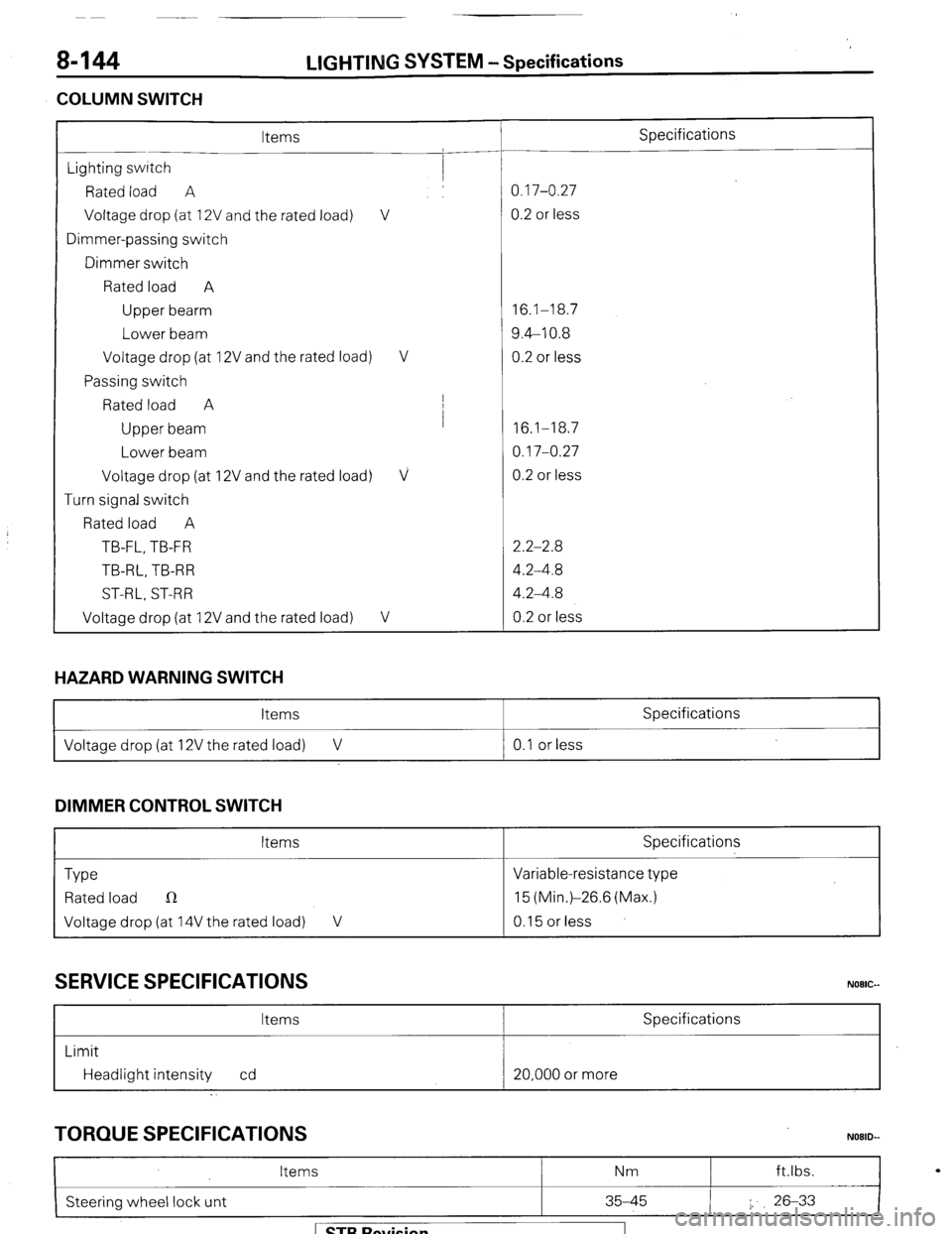
8-144
COLUMN SWITCH LIGHTING
SYSTEM -Specifications
Items Specifications
Lighting switch
Rated load A 0.17-0.27
Voltage drop (at 12V and the rated load) V 0.2 or less
Dimmer-passing switch
Dimmer switch
Rated load A
Upper bearm 16.1-18.7
Lower beam 9.4-10.8
Voltage drop (at 12V and the rated load) V 0.2 or less
Passing switch
Rated load A I
Upper beam I
16.1-18.7
Lower beam 0.17-0.27
Voltage drop (at 12V and the rated load)
V 0.2 or less
Turn signal switch
Rated load A
TB-FL, TB-FR 2.2-2.8
TB-RL, TB-R R 4.2-4.8
ST-RL, ST-RR 4.2-4.8
Voltage drop (at 12V and the rated load)
V 0.2 or less
HAZARD WARNING SWITCH
Items Specifications
I Voltage drop (at 12V the rated load) V 0.1 or less
I
DIMMER CONTROL SWITCH
Items Specifications
Type Variable-resistance type
Rated load n 15 (Min.)-26.6 (Max.)
Voltage drop (at 14V the rated load) V 0.15 or less
SERVICE SPECIFICATIONS
Items Specifications
Limit
Headlight intensity cd 20,000 or more
TORQUE SPECIFICATIONS
I
Items Nm ft.lbs.
N08lb
Steering wheel lock unt 35-45 I. 26-33
I
1 STB Revision
Page 167 of 284
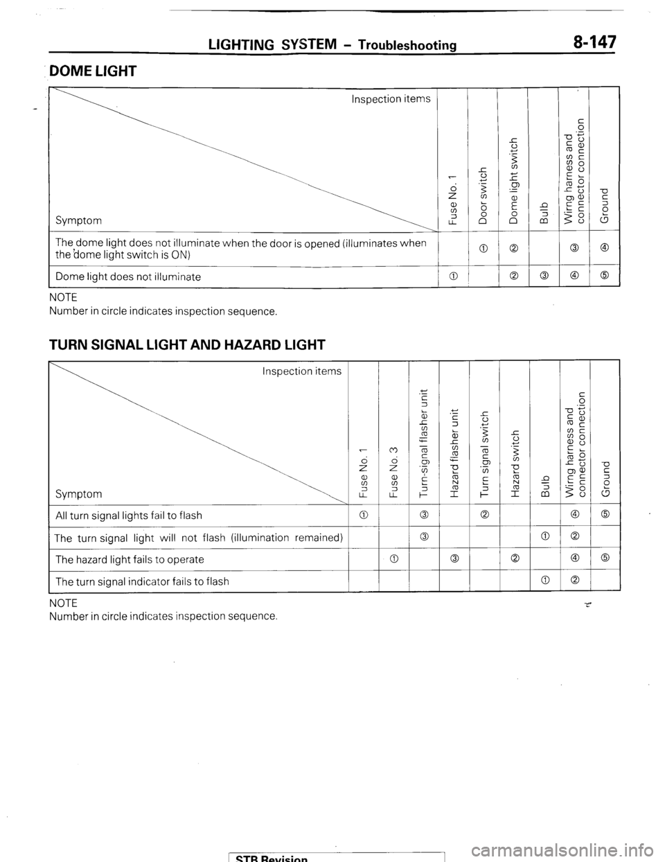
LIGHTING SYSTEM - Troubleshooting 8-147
DOME LIGHT
Inspection items
The dome light does not illuminate when the door is opened (illuminates when
the borne light switch is ON)
I
Dome light does not illuminate 0
I
NOTE
Number in circle indicates inspection sequence.
TURN SIGNAL LIGHT AND HAZARD LIGHT
Inspection items
Symptom
All turn signal lights fail to flash
The turn signal light will not flash (illumination remained)
The hazard light fails to operate
The turn signal indicator fails to flash
NOTE
Number in circle indicates inspection sequence
1 STB Revision