ESP MITSUBISHI MONTERO 1987 1.G Workshop Manual
[x] Cancel search | Manufacturer: MITSUBISHI, Model Year: 1987, Model line: MONTERO, Model: MITSUBISHI MONTERO 1987 1.GPages: 284, PDF Size: 14.74 MB
Page 2 of 284
2 INTRODUCTION - How To Use This Manual
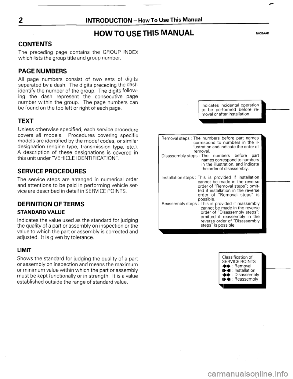
HOW TO USE THIS MANUAL NOOBAAK
CONTENTS
The preceding page contains the GROUP INDEX
which lists the group title and group number.
PAGE NUMBERS
All page numbers consist of two sets of digits
separated by a dash. The digits preceding the dash
identify the number of the group. The digits follow-
ing the dash represent the consecutive page
number within the group. The page numbers can
be found on the top left or right of each page.
TEXT
Unless otherwise specified, each service procedure
covers all models. Procedures covering specific
models are identified by the model codes, or similar
designation (engine type, transmission type, etc.).
A description of these designations is covered in
this unit under “VEHICLE IDENTIFICATION”.
SERVICE PROCEDURES
The service steps are arranged in numerical order
and attentions to be paid in performing vehicle ser-
vice are described in detail in SERVICE POINTS.
DEFINITION OF TERMS
STANDARD VALUE
Indicates the value used as the standard for judging
the quality of a part or assembly on inspection or the
value to which the part or assembly is corrected and
adjusted. It is given by tolerance.
LIMIT
Shows the standard for judging the quality of a part
or assembly on inspection and means the maximum
or minimum value within which the part or assembly
must be kept functionally or in strength. It is a value
established outside the range of standard value. Installation steps
Indicates incidental operation
piiiKL=l-
Removal steps : The numbers before part names
correspond to numbers in the il-
lustration and indicate the order of
removal.
Disassembly steps : The numbers before part
names correspond to numbers
in the illustration, and indicate
the order of disassembly.
This is provided if installation
cannot be made in the reverse
order of “Removal steps”; omit-
ted if installation in the reverse
order of “Removal steps” is
possible.
.
Reassembly steps : I his IS provided It reassembly
cannot be made in the reverse
order of “Disassembly steps”;
omitted if reassembly in the
reverse order of “Disassembly
steps” is possible.
Classification of
SERVICE ROINTS
Oe : Removal
** : Installation
Oe : Disassembly
I)+ : Reassembly
Page 3 of 284
INTRODUCTION - H
ow To Use This Manual 3
-L
!
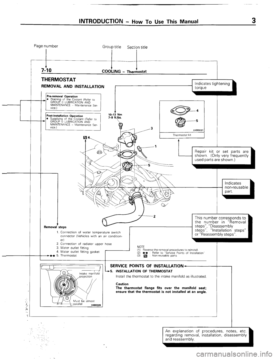
Page number
Group title
Section title
THERMOSTAT
REMOVAL AND INSTALLATION
I
I I
L
1 torque
Removal +
I s 0480031
Thermostat kit
Repair kit or set parts are
1. Connectw of water temperature switch
connector (Vehicles with an air condltlon-
eri
2 Connection of radiator upper hose
3 Water outlet fitting
4 Water outlet fitting gasket
B~C 5. Thermostat I
This number corresponds to
the number in “Removal
steps”, ” Disassembly
steps”, “Installation steps”
or “Reassembly steps”.
NOTE
(1)
(3)
q Nowreusable parts
-r Reverse the removal procedures to reinstall
12) l * : Refer to “Sewce Points of Installation”
SERVICE POINTS OF lNSTALLATlON--
45. INSTALLATION OF THERMOSTAT
Install the thermostat to the Intake manifold as illustrated.
Caution
The thermostat flange fits over the manifold seat;
ensure that the thermostat is not installed at an angle.
An explanation of procedures, notes, etc.
(and reassembly. ’ ’ -1 regarding removal installation disassembly
Page 14 of 284
INTRODUCTION - Towing and Hoisting
TOWING AND HOISTING NOOGA-
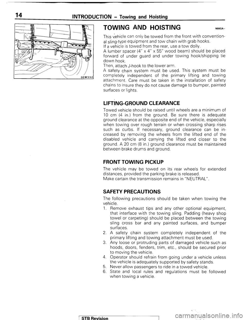
This vehicle can only be towed from the front with convention-
al sling-type equipment and tow chain with grab hooks.
If a vehicle is towed from the rear, use a tow dolly.
A lumber spacer (4” x 4” x 55” wood beam) should be placed
forward of under guard and under towing hook/shipping tie
down hook.
Then, attach J-hook to the lower arm.
A safety chain system must be used. This system must be
completely independent of the primary lifting and towing
attachment. Care must be taken in the installation of safety
chains to insure they do not cause damage to bumper, painted
surfaces or lights.
LIFT!NG-GROUND CLEARANCE
Towed vehicle should be raised until wheels are a minimum of
10 cm (4 in.) from the ground. Be sure there is adequate
ground clearance at the opposite end of the vehicle, especially
when towing over rough terrain or when crossing sharp rises
such as curbs. If necessary, ground clearance can be in-
creased by removing the wheels from the lifted end of the
disabled vehicle and carrying the lifted end closer to the
ground. A 20 cm (8 in.) ground clearance must be maintained
between brake drums and ground.
FRONT TOWING PICKUP
The vehicle may be towed on its rear wheels for extended
distances, provided the parking brake is released.
Make cartain the transmission remains in “NEUTRAL”.
SAFETY PRECAUTIONS
The following precautions should be taken when towing the
vehicle.
1. Remove exhaust tips and any other optional equipment,
that interface with the towing sling. Padding (heavy shop
towel or carpeting) should be placed between the towing
sling cross bar and any painted surfaces, and bumper
surfaces.
2. A safety chain system completely independent of the
primary lifting and towing attachment must be used.
3. Any loose or protruding parts of damaged vehicle such as
hoods, doors, fenders, trim, etc., should be secured prior
to moving the vehicle.
4. Operator should refrain from going under a vehicle unless
the vehicle is adequately supported by safety stands.
5. Never allow passengers to ride in a towed vehicle.
6. State and local rules and regulations must be followed
when towing a vehicle.
1 STB Revision
‘
Page 34 of 284
8-14 WIRING HARNESS - Troubleshooting
1680222
Changeover knob 1680224
1680225 1
1680226
INSPECTION
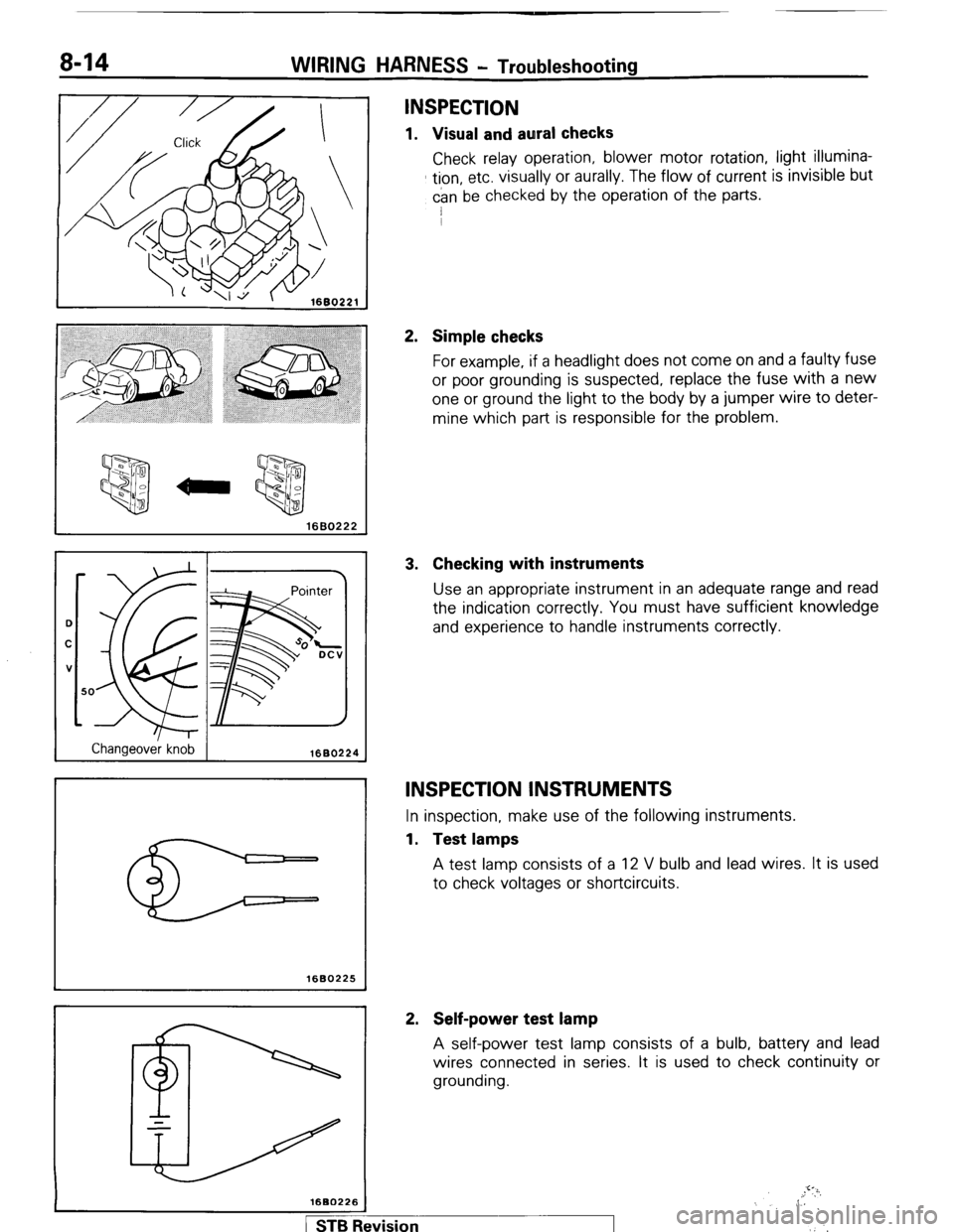
1. Visual and aural checks
Check relay operation, blower motor rotation, light illumina-
tion, etc. visually or aurally. The flow of current is invisible but
can be checked by the operation of the parts.
I
2. Simple checks
For example, if a headlight does not come on and a faulty fuse
or poor grounding is suspected, replace the fuse with a new
one or ground the light to the body by a jumper wire to deter-
mine which part is responsible for the problem.
3. Checking with instruments
Use an appropriate instrument in an adequate range and read
the indication correctly. You must have sufficient knowledge
and experience to handle instruments correctly.
INSPECTION INSTRUMENTS
In inspection, make use of the following instruments.
1. Test lamps
A test lamp consists of a 12 V bulb and lead wires. It is used
to check voltages or shortcircuits.
2. Self-power test lamp
A self-power test lamp consists of a bulb, battery and lead
wires connected in series. It is used to check continuity or
grounding.
,.!‘?i,
,, 6
,‘.’
1 STB Revision
Page 37 of 284
Normal close INC) type
Deenergized state
Energized state
I
WIRING HARNESS - Troubleshooting 8-17
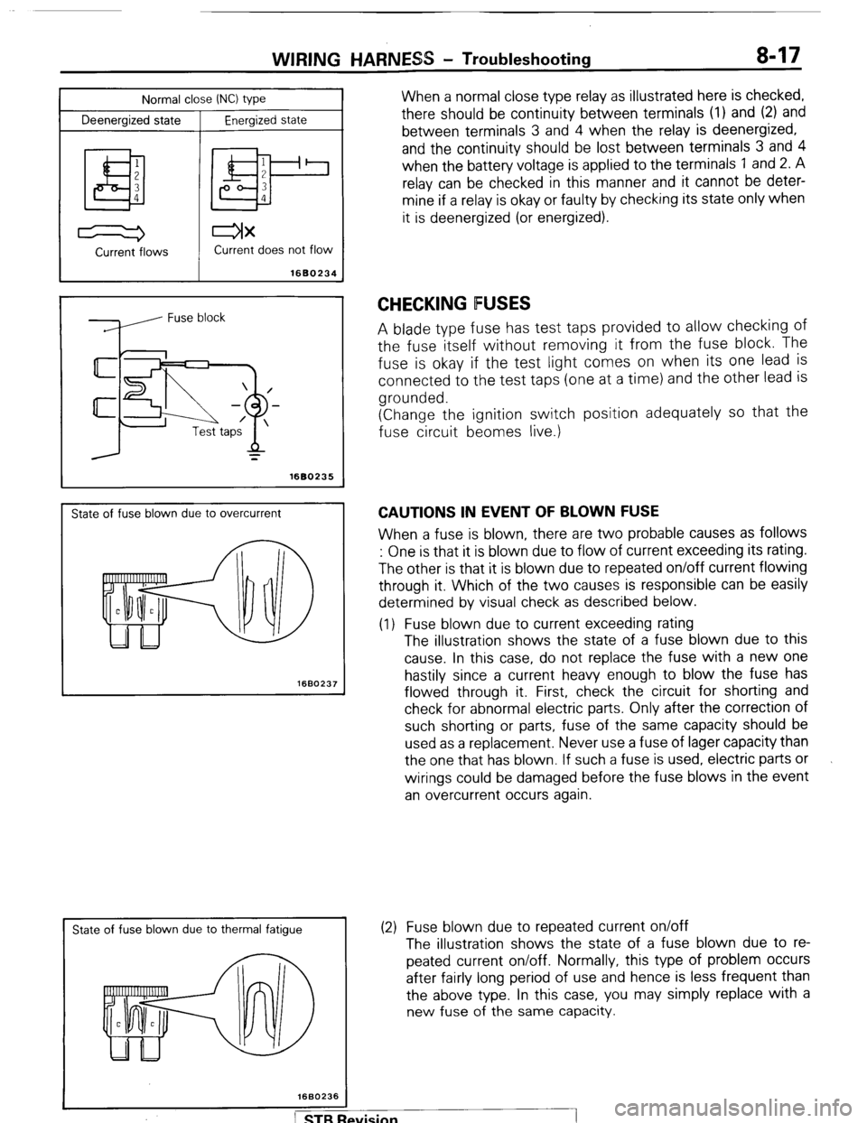
When a normal close type relay as illustrated here is checked,
there should be continuity between terminals (1) and (2) and
between terminals 3 and 4 when the relay is deenergized,
and the continuity should be lost between terminals 3 and 4
when the battery voltage is applied to the terminals 1 and 2. A
relay can be checked in this manner and it cannot be deter-
mine if a relay is okay or faulty by checking its state only when
it is deenergized (or energized).
Current -flows Current does not flow
1680234
=
1680235
State of fuse blown due to overcurrent
1660237
I
State of fuse blown due to thermal fatigue
CHECKING FUSES
A blade type fuse has test taps provided to allow checking of
the fuse itself without removing it from the fuse block. The
fuse is okay if the test light comes on when its one lead is
connected to the test taps (one at a time) and the other lead is
grounded.
(Change the ignition switch position adequately so that the
fuse circuit beomes live.)
CAUTIONS IN EVENT OF BLOWN FUSE
When a fuse is blown, there are two probable causes as follows
: One is that it is blown due to flow of current exceeding its rating.
The other is that it is blown due to repeated on/off current flowing
through it. Which of the two causes is responsible can be easily
determined by visual check as described below.
(1) Fuse blown due to current exceeding rating
The illustration shows the state of a fuse blown due to this
cause. In this case, do not replace the fuse with a new one
hastily since a current heavy enough to blow the fuse has
flowed through it. First, check the circuit for shorting and
check for abnormal electric parts. Only after the correction of
such shorting or parts, fuse of the same capacity should be
used as a replacement. Never use a fuse of lager capacity than
the one that has blown. If such a fuse is used, electric parts or
wirings could be damaged before the fuse blows in the event
an overcurrent occurs again.
(2) Fuse blown due to repeated current on/off
The illustration shows the state of a fuse blown due to re-
peated current on/off. Normally, this type of problem occurs
after fairly long period of use and hence is less frequent than
the above type. In this case, you may simply replace with a
new fuse of the same capacity.
Page 42 of 284
8-22 WIRING HARNESS - How to Read Wiring Diagrams
HOW TO READ CIRCUIT DIAGRAMS
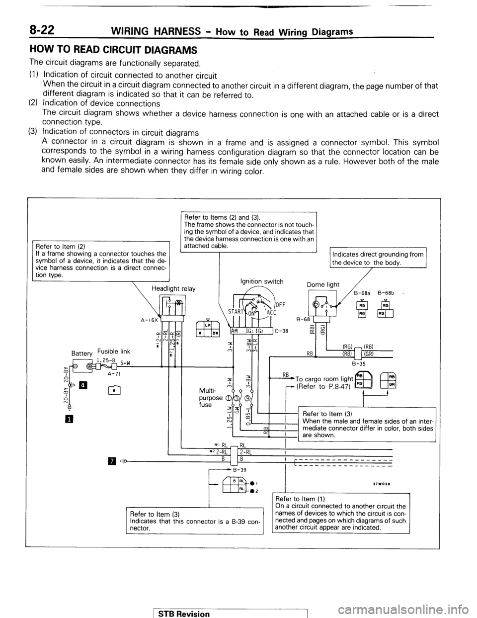
The circuit diagrams are functionally separated.
(1) Indication of circuit connected to another circuit
When the circuit in a circuit diagram connected to another circuit in a different diagram, the page number of that
different diagram is indicated so that it can be referred to.
(2) Indication of device connections
The circuit diagram shows whether a device harness connection is one with an attached cable or is a direct
connection type.
(3) Indication of connectors in circuit diagrams
A connector in a circuit diagram is shown in a frame and is assigned a connector symbol. This symbol
corresponds to the symbol in a wiring harness configuration diagram so that the connector location can be
known easily. An intermediate connector has its female side only shown as a rule. However both of the male
and female sides are shown when they differ in wiring color.
Refer to Item (2)
If a frame showing a connector touches the
?. it indicates that the de-
a direct connec- symbol of a device
vice
harness connectlon IS
tion type.
Refer to Items (2) and (3).
The frame shows the connector is not touch- ing the symbol of a device, and indicates that
the device harness connection is one with an
attached cable.
Indicates direct grounding from
the device to the bodv.
Ignition switch
Dome light
/
17 /B-6& B-68b
(RG) - (RB)
RB-
(REV 1 I (GR)
L-2
B-35
1 *I RL - RL
I
**2-RL 1 Z-RL I
BI B ----- ---- --------
L ----_ __---___----
r------B-39
43 BRL *I
31103LI RL*2 _
Refer to Item (1)
Refer to item (3)
Indicates that this connector is a B-39 con-
nectar. On a circuit connected to another circuit the
names of devices to which the circuit is con-
nected and pages on which diagrams of such
another circuit appear are indicated.
1 STB Revision 1
Page 43 of 284
WIRING HARNESS - HOW BO Read Wiring Diagrams 8-23
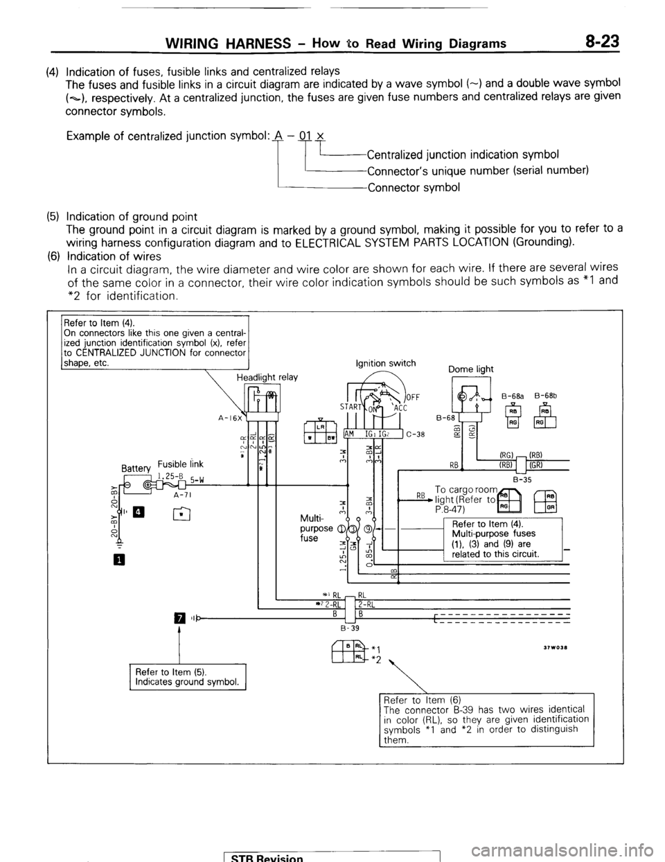
(4) Indication of fuses, fusible links and centralized relays
The fuses and fusible links in a circuit diagram are indicated by a wave symbol (-) and a double wave symbol
(~1, respectively. At a centralized junction, the fuses are given fuse numbers and centralized relays are given
connector symbols.
Example of centralized junction symbol: A - 01 x
Centralized junction indication symbol
Connector’s unique number (serial number)
Connector symbol
(5) Indication of ground point
The ground point in a circuit diagram is marked by a ground symbol, making it possible for you to refer to a
wiring harness configuration diagram and to ELECTRICAL SYSTEM PARTS LOCATION (Grounding).
(6) Indication of wires
In a circuit diagram, the wire diameter and wire color are shown for each wire. If there are several wires
of the same color in a connector, their wire color indication symbols should be such symbols as “I and
“2 for identification.
On connectors like this one given a central-
to CENTRALIZED JUNCTION for connector
1 shaoe. etc.
-I Headlight relay ignition switch
Dome light
I II I B-35 B-68b
P:8-47)
IEU
I ’ 2 I
RL
2-RL
0 III- BI B -----____________
L - - - - - _ _ _ _ _ __ _ _ _ _ _
B-39
Refer to Item (5).
Refer to Item (6)
The connector B-39 has two wires identical
in color (RL), so they are given identification
symbols *I and *2 in order to distinguish
them. 1 ST6 Revision
Page 238 of 284
24-2 HEATERS - General Information
GENERAL INFORMATION 24BAAD
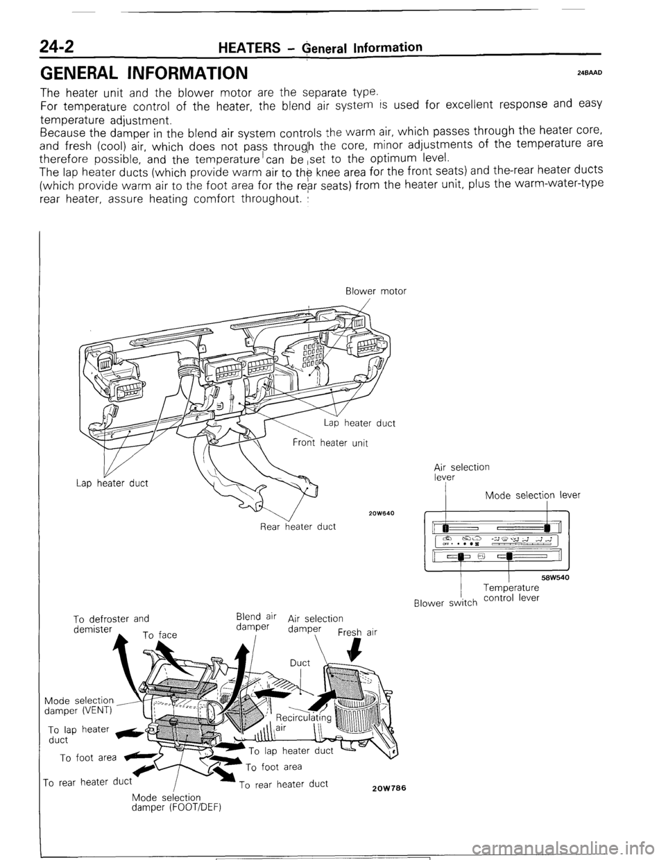
The heater unit and the blower motor are the separate type.
For temperature control of the heater, the blend air system is used for excellent response and easy
temperature adjustment.
Because the damper in the blend air system controls the warm air, which passes through the heater core,
and fresh (cool) air, which does not pass througlh the core, minor adjustments of the temperature are
therefore possible, and the temperature’can be ,set to the optimum level.
The lap heater ducts (which provide warm air to th$ knee area for the front seats) and the-rear heater ducts
(which provide warm air to the foot area for the rebr seats) from the heater unit, plus the warm-water-type
rear heater, assure heating comfort throughout. :
Blower motor
/
2OW640
Rear heater duct ;;eselection
I Mode selection lever
I I
58W540 Temperature
Blower switch contra’ lever To defroster and
Blend air Air selection
demister damper damper
Fresh air
Mode selection
damper (VENT) To lap heater &@
duct To foot area
ro rear heater duct To rear heater duct 2OW706 Mode selection damper (FOOT/DEF)
1 ST6 Revision
Page 264 of 284
24-28 AIR-CONDITIONING-Safety Precautions
SAFETY PRECAUTIONS N24PAAB
SAFETY PRECAUTIONS
I
The refrigerant used in all air-conditioning installations is R-12. It is transparent and colorless in both the liquid and
vapor state. Since it has a boiling point of -29.8T (-21.7”F). at atmospheric pressure, it will be a vapor at all normal
temperatures and pressures. The vapor is heavier than air, non- flammable, and nonexplosive. It is nonpoisonous
except when it is in direct contact with open flame. It is noncorrosive except when combined with water. The
following precautions must be observed when handling R-12.
Caution
Wear
safety goggles when servicing the refrigeration system.
R-12 evaporates so rapidly at normal atmospheric pressures and temperatures that it tends to freeze anything it
contacts. For this reason, extreme care must be taken to prevent any liquid refrigerant from contacting the skin and
especially the eyes.
Always wear safety goggles when servicing the refrigeration part of the air- conditioning system. Keep a bottle of
sterile mineral oil handy when working on the refrigeration system. Should any liquid refrigerant get into the eyes,
use a few drops of mineral oil to wash them out. RI12 is rapidly absorbed by the oil. Next, splash the eyes with
plenty of cold water. Call your doctor immediately even though irritation has ceased after treatment.
Caution
Do not heat R-12 above 52°C (125°F).
In most instances, moderate heat is required to bring the pressure of the refrigerant in its container above the
pressure of the system when charging or adding refrigerant. A bucket or large pan of hot water not over 52°C
(125°F) is all the heat required for this purpose. Do not heat the refrigerant container with a blow torch or any other
means that would raise temperature and pressure above this temperature. Do not weld or steam clean on or near
the system components or refrigerant lines.
Caution
Keep R-12 containers upright when charging the system.
When metering R-12 into the refrigeration system, keep the supply tank or cans in an upright position. If the
refrigerant container is on its side or upside down, liquid refrigerant will enter the system and damage the
compressor.
Caution
Always work in a well-ventilated room.
Good ventilation is vital in the working area. Always discharge the refrigerant into the service bay exhaust system
or outside the building. Large quantities of refrigerant vapor in a small, poorly ventilated room can displace the air
and cause suffocation.
Although R-12 vapor is normally nonpoisonous, contact with an open flame can cause the vapor to become very
poisonous. Do not discharge large quantities of refrigerant in an area having an open flame. A poisonous gas is
producted when using the flame-type leak detector. Avoid inhaling the fumes from the leak detector.
Caution
Do not allow liquid refrigerant to touch bright metal.
Refrigerant will tarnish bright metal and chrome surfaces, and in combination with moisture’can severely corrode
all metal surfaces.
/ STB Revision
-I
Page 270 of 284
24-34 AIR-CONDITIONING-Service Adiustment Procedures
r---- :
:ES
Dry bulb therr&neter
2OW825
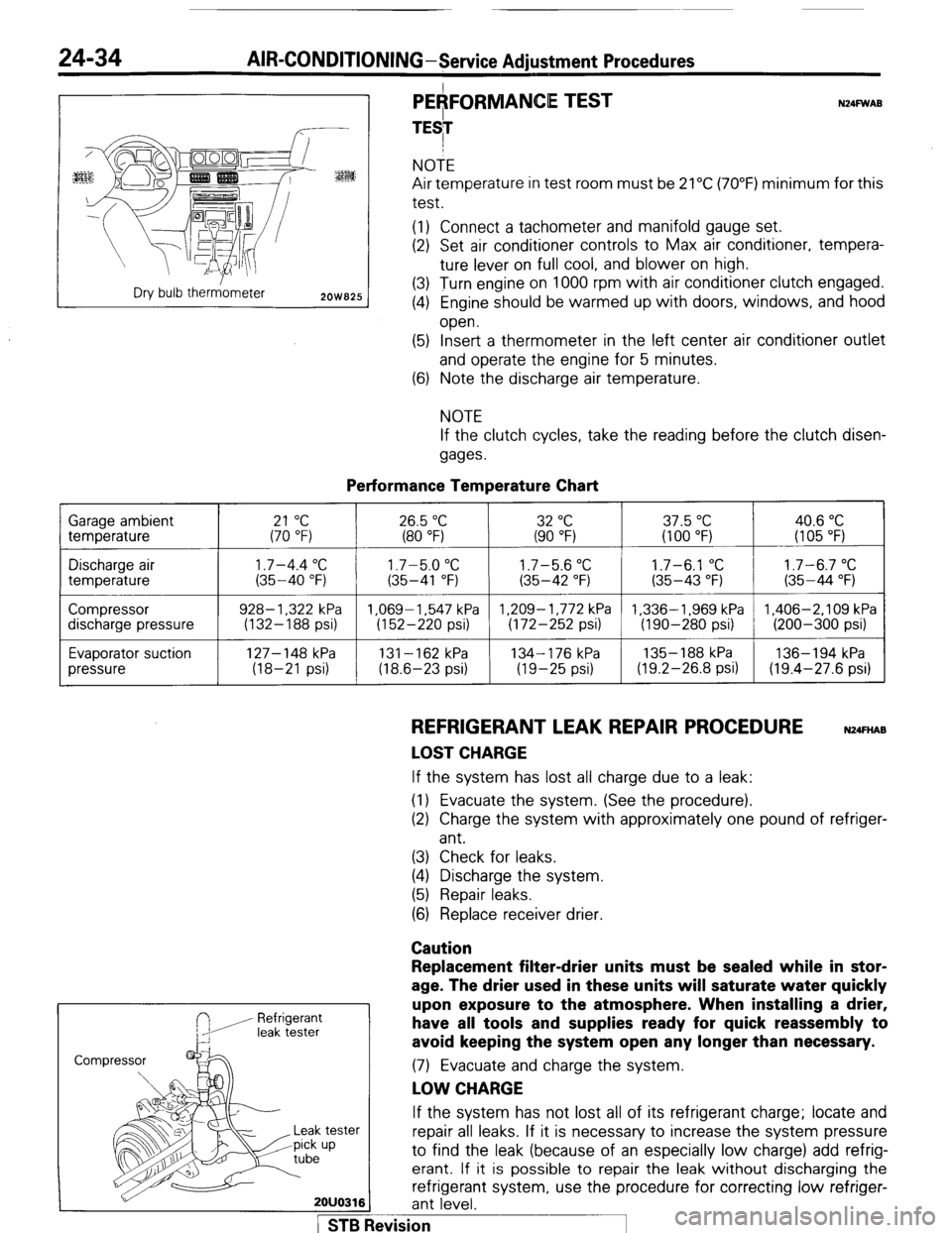
PEAFORMANCE TEST
TESI N24FWAB NOTE
Air temperature in test room must be 21°C (70°F) minimum for this
test.
(1) Connect a tachometer and manifold gauge set.
(2) Set air conditioner controls to Max air conditioner, tempera-
ture lever on full cool, and blower on high.
(3) Turn engine on 1000 rpm with air conditioner clutch engaged.
(4) Engine should be warmed up with doors, windows, and hood
open.
(5) Insert a thermometer in the left center air conditioner outlet
and operate the engine for 5 minutes.
(6) Note the discharge air temperature.
NOTE
If the clutch cycles, take the reading before the clutch disen-
gages.
Performance Temperature Chart Garage ambient
temperature
21 “C 26.5 “C 32 “C 37.5 “C 40.6 “C (70 “F) (80 “F) (90 “F) (100 “F) (I 05 “F)
Discharge air
temperature
Compressor
discharge pressure
Evaporator suction
pressure
1.7-4.4 “C 1.7-5.0 “C 1.7-5.6 “C 1.7-6.1 “C 1.7-6.7 “C (35-40 “F) (35-41 “F) (35-42 “F) (35-43 “F) (35-44 “F)
928- 1,322 kPa 1.069-1.547 kPa 1,209-1,772 kPa 1,336-1,969 kPa 1,406-2,109 kPa
(132-188 psi) (152-220 psi) (172-252 psi) (190-280 psi) (200-300 psi)
127-148 kPa
131-162 kPa 134-176 kPa 135- 188 kPa 136-194 kPa
(18-21 psi) (18.6-23 psi) (19-25 psi) (19.2-26.8 psi) (19.4-27.6 psi)
REFRIGERANT LEAK REPAIR PROCEDURE N24FnAB
LOST CHARGE If the system has lost all charge due to a leak:
(1) Evacuate the system. (See the procedure).
(2) Charge the system with approximately one pound of refriger-
ant.
(3) Check for leaks.
(4) Discharge the system.
(5) Repair leaks.
(6) Replace receiver drier.
Caution
Refrigerant
leak tester
Replacement filter-drier units must be sealed while in stor-
age. The drier used in these units will saturate water quickly
upon exposure to the atmosphere. When installing a drier,
have all tools and supplies ready for quick reassembly to
avoid keeping the system open any longer than necessary. (7) Evacuate and charge the system.
LOW CHARGE If the system has not lost all of its refrigerant charge; locate and
tester repair all leaks. If it is necessary to increase the system pressure
up to find the leak (because of an especially low charge) add refrig-
erant. If it is possible to repair the leak without discharging the
refrigerant system, use the procedure for correcting low refriger-
2OUO316 ant level.
1 STB Revision