ignition system MITSUBISHI MONTERO 1987 1.G User Guide
[x] Cancel search | Manufacturer: MITSUBISHI, Model Year: 1987, Model line: MONTERO, Model: MITSUBISHI MONTERO 1987 1.GPages: 284, PDF Size: 14.74 MB
Page 100 of 284
8-80 CHARGING SYSTEM - Service Adjustment Procedures
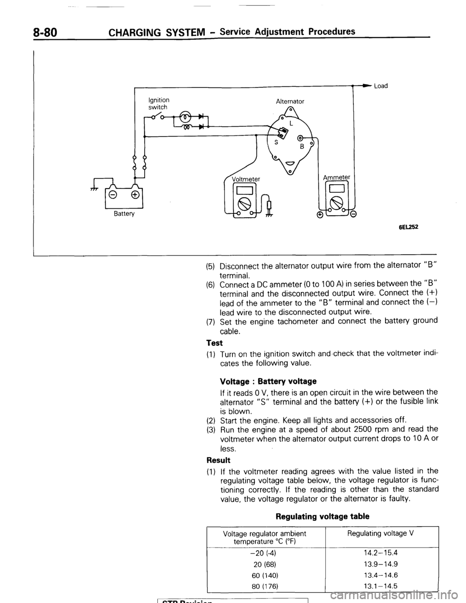
Ignition
switch Alternator
Voltmeter
I
lid-hi! @ Ammeter e Load
6EK52
(5) Disconnect the alternator output wire from the alternator “B”
terminal.
(6) Connect a DC ammeter (0 to 100 A) in series between the “B”
terminal and the disconnected output wire. Connect the (+I
lead of the ammeter to the “B” terminal and connect the (-1
lead wire to the disconnected output wire.
(7) Set the engine tachometer and connect the battery ground
cable.
Test
(1) Turn on the ignition switch and-check that the voltmeter indi-
cates the following value.
Voltage : Battery voltage
If it reads 0 V, there is an open circuit in the wire between the
alternator “S” terminal and the battery (+) or the fusible link
is blown.
(2) Start the engine. Keep all lights and accessories off.
(3) Run the engine at a speed of about 2500 rpm and read the
voltmeter when the alternator output current drops to 10 A or
less.
Result
(1) If the voltmeter reading agrees with the value listed in the
regulating voltage table below, the voltage regulator is func-
tioning correctly. If the reading is other than the standard
value, the voltage regulator or the alternator is faulty.
Regulating voltage table
Voltage regulator ambient Regulating voltage V
temperature “C (“F)
-20 (-4) 14.2-15.4
20 (68) 13.9-14.9
60 (140) 13.4-14.6
80 (176) 13.1-14.5
1 STB Revision
Page 101 of 284
CHARGING SYSTEM - Service Adjustment Procedures 8-81
(2) Upon completion of the test, set the engine speed at idle and
turn off the ignition switch.
(3) Disconnect the battery ground cable.
(4) Remove the test voltmeter and ammeter and the engine ta-
chometer.
(5) Connect the alternator output wire to the alternator “B” ter-
minal.
(6) Connect the battery ground cable.
ll3Y1848 2. Remove battery from vehicle.
Caution
White
I Blue
I Care should be taken in the event battery case is cracked
or leaking to protect hands from the electrolyte. A suit-
able pair of rubber gloves (not the household type) should
be worn when removing battery by hand.
3. Inspect battery carrier for damage caused by loss of acid from
battery. If acid damage is present, it will be necessary to clean
area with a solution of clean warm water and baking soda.
Scrub area with a stiff bristle brush and wipe off with a cloth
moistened with ammonia or baking soda in water.
4. Clean top of battery with same solutions as described in Step
(3).
INSPECTION OF BATTERY NOBEIBA
VISUAL INSPECTION OF BATTERY (1)
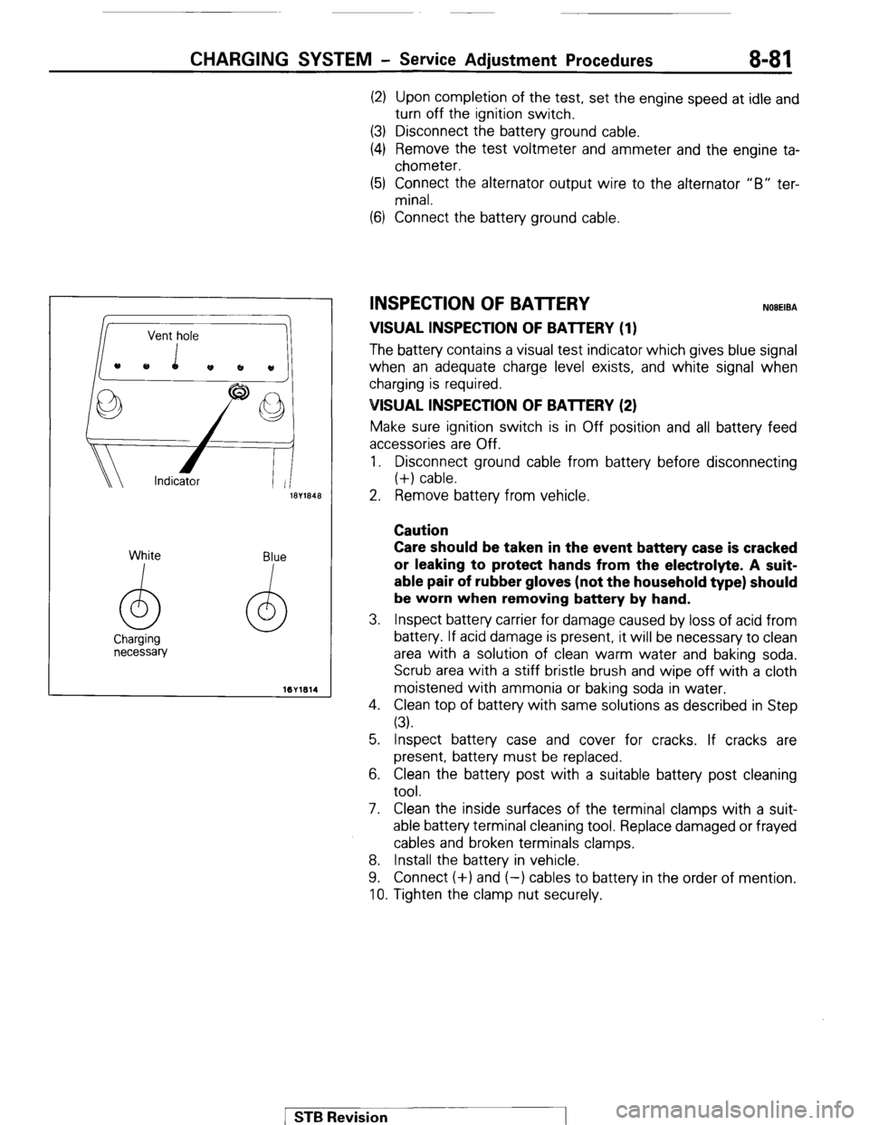
The batten/ contains a visual test indicator which gives blue signal
when an adequate charge level exists, and white signal when
charging is required.
VISUAL INSPECTION OF BAlTERY (2)
Make sure ignition switch is in Off position and all battery feed
accessories are Off.
1. Disconnect ground cable from battery before disconnecting
(+) cable.
5. Inspect battery case and cover for cracks. If cracks are
present, battery must be replaced.
6. Clean the battery post with a suitable battery post cleaning
tool.
7. Clean the inside surfaces of the terminal clamps with a suit-
able battery terminal cleaning tool. Replace damaged or frayed
cables and broken terminals clamps.
8. Install the battery in vehicle.
9. Connect (+) and (-) cables to battery in the order of mention.
10. Tighten the clamp nut securely.
1 STB Revision
Page 111 of 284
STARTING SYSTEM-General Information 8-91
STARTING SYSTEM
GENERAL INFORMATION
NOBFAAJ
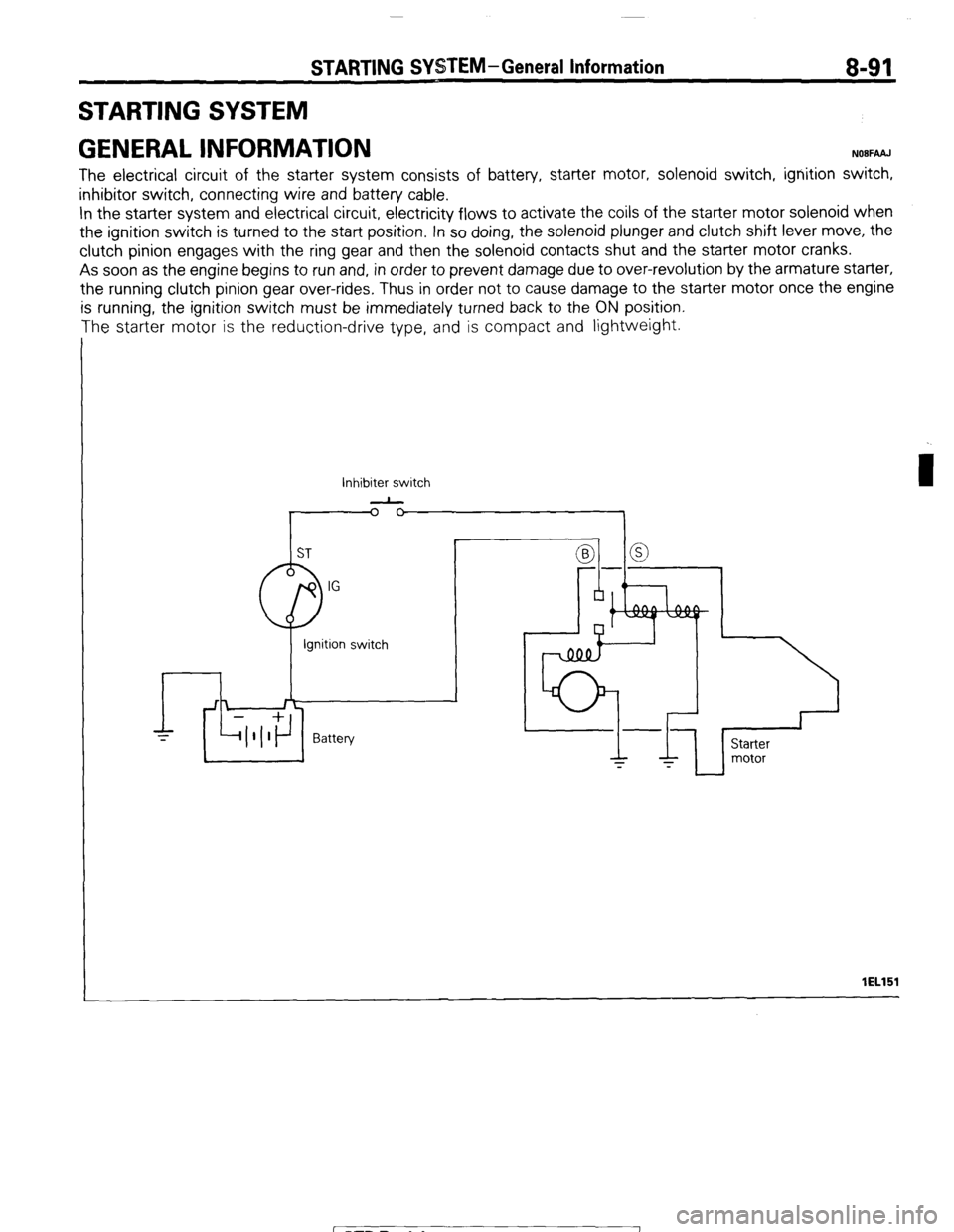
The electrical circuit of the starter system consists of battery, starter motor, solenoid switch, ignition switch,
inhibitor switch, connecting wire and battery cable.
In the starter system and electrical circuit, electricity flows to activate the coils of the starter motor solenoid when
the ignition switch is turned to the start position. In so doing, the solenoid plunger and clutch shift lever move, the
clutch pinion engages with the ring gear and then the solenoid contacts shut and the starter motor cranks.
As soon as the engine begins to run and, in order to prevent damage due to over-revolution by the armature starter,
the running clutch pinion gear over-rides, Thus in order not to cause damage to the starter motor once the engine
is running, the ignition switch must be immediately turned back to the ON position.
The starter motor is the reduction-drive type, and is compact and lightweight.
Inhibiter switch
-
I lEL151
1 STB Revision
Page 114 of 284
8-94 STARTING SYSTEM -Troubleshooting
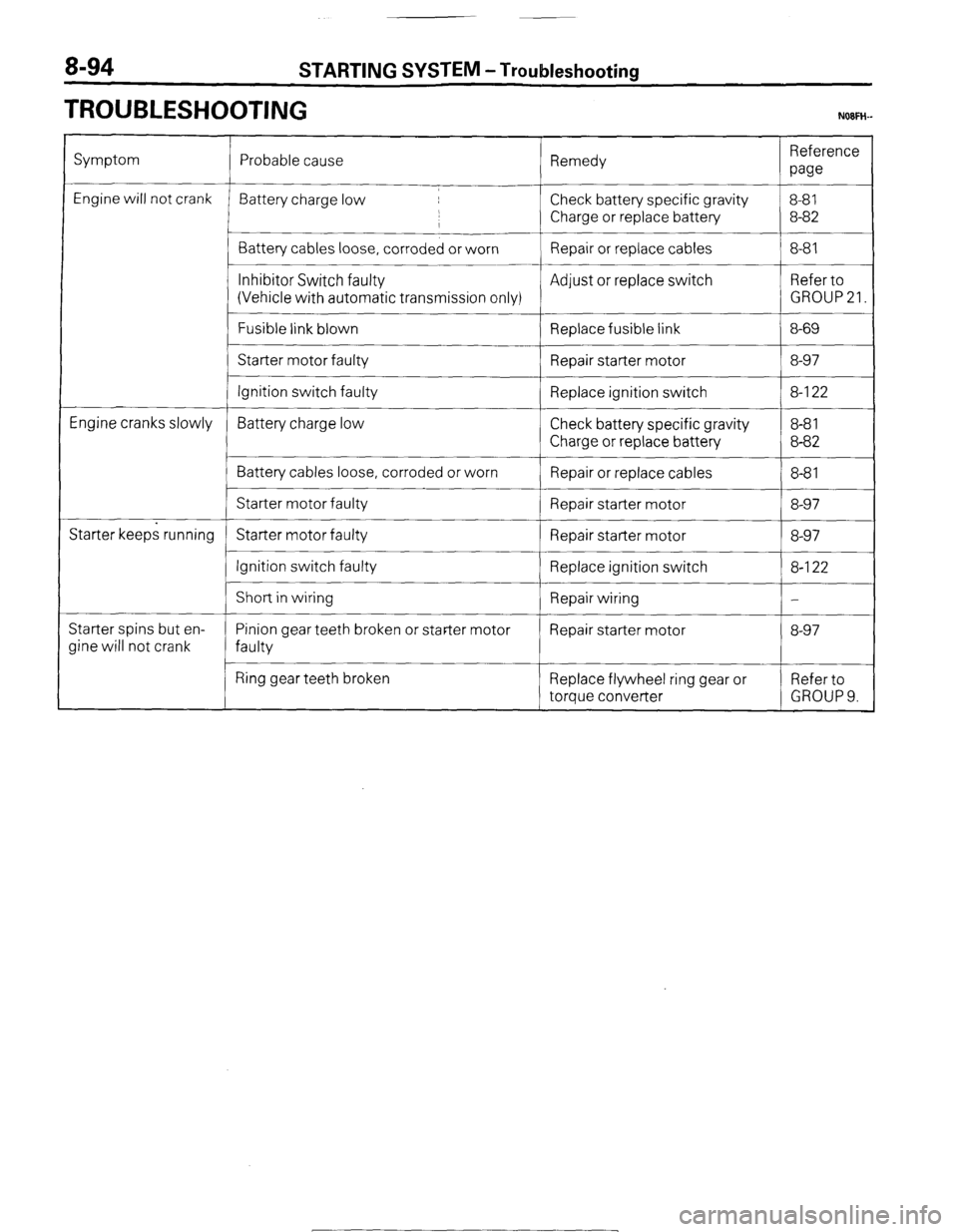
TROUBLESHOOTING NOFH-
Symptom
Engine will not crank
Engine cranks slowly
Starter keeps running
Starter spins but en-
Jine will not crank Probable cause Remedy Reference
paw
Battery charge low Check battery specific gravity 8-81
,
I Charge or replace battery 8-82
Battery cables loose, corroded or worn Repair or replace cables 8-81
__~
Inhibitor Switch faulty Adjust or replace switch Refer to
(Vehicle with automatic transmission only) GROUP 21.
Fusible link blown
Replace fusible link 8-69
Starter motor faulty
Repair starter motor 8-97
Ignition switch faulty Replace ignition switch 8-l 22
Battery charge low Check battery specific gravity 8-8 1
Charge or replace battery 8-82
Battery cables loose, corroded or worn
Repair or replace cables 8-8 1
Starter motor faulty Repair starter motor 8-97
Starter motor faulty Repair starter motor 8-97
Ignition switch faulty
Replace ignition switch 8-l 22
I
Short in wiring
Repair wiring -
Pinion gear teeth broken or starter motor Repair starter motor 8-97
faulty
Ring gear teeth broken Replace flywheel ring gear or Refer to
torque converter GROUP 9.
1 STB Revision
-7
Page 115 of 284
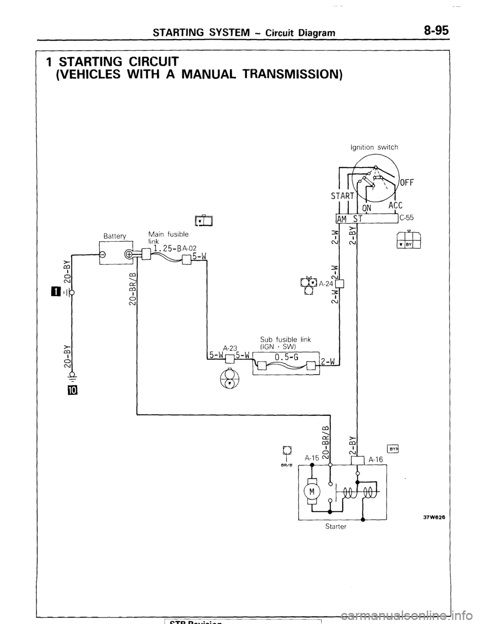
STARTING SYSTEM - Circuit Diagram 8-95
1 STARTING CIRCUIT
(VEHICLES WITH A MANUAL TRANSMISSION)
11171 w
$in fusible
START
I k
9
OFF
ON ACC
ST
c-55
.I
m I BY
Sub fusible link Ignition switch
Starter
37W626 / STB Revision
Page 116 of 284
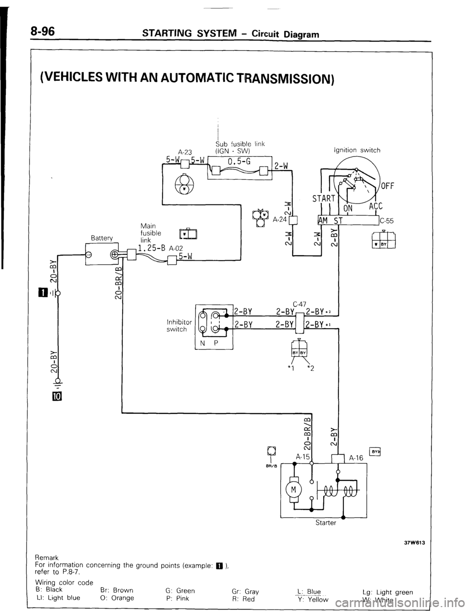
8-96 STARTING SYSTEM - Circuit Diagram
(VEHICLES WITH AN AUTOMATIC TRANSMISSION)
I
Sub fusible link
A-23 (IGN . SW)
_ 5-WI-754 1
0.5-G 1, 1,
L-l m 1 L-W
Battery Ignition switch
c-47
2-BY-Z-BY*2
N P
!-BY Z-BY1 (Z-BY*]
L-l
R BY BY
“I “2
Remark
For information concerning the ground points (example:
q ),
refer to P.8-7.
Wiring color code
B: Black
Br: Brown
G: Green
Gr: Gray L: Blue
LI: Light blue
0: Orange P: Pink Lg: Light green
R: Red
Y: Yellow
W: White
STB Revision
Page 125 of 284
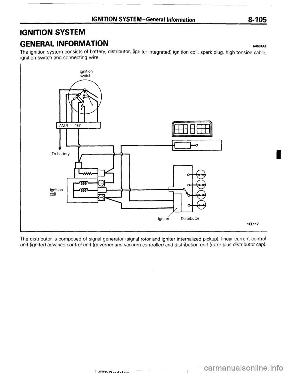
IGNITION SYSTEM -General Information 8-105
IGNITION SYSTEM
GENERAL INFORMATION
NOUGAAB
The ignition system consists of battery, distributor, (igniter-integrated) ignition coil, spark plug, high tension cable,
ignition switch and connecting wire.
Ignition
switch
0
m
I
1 AMR 1Gl
I
Ignition
coil
r
Ignite; Distributor
lEL117
The distributor is composed of signal generator (signal rotor and igniter internalized pickup), linear current control
unit (igniter) advance control unit (governor and vacuum controller) and distribution unit (rotor plus distributor cap).
Page 126 of 284
IGNITION SYSTEM-General Information
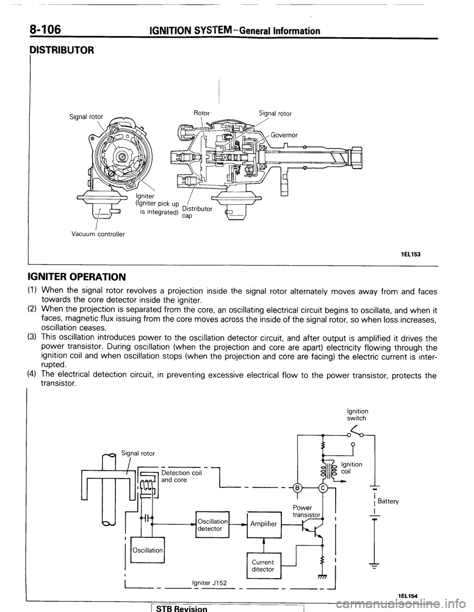
IISTRIBUTOR
Vacuum controller
lEL153
IGNITER OPERATION
(1) When the signal rotor revolves a projection inside the signal rotor alternately moves away from and faces
towards the core detector inside the igniter.
(2) When the projection is separated from the core, an oscillating electrical circuit begins to oscillate, and when it
faces, magnetic flux issuing from the core moves across the inside of the signal rotor, so when loss increases,
oscillation ceases.
(3) This oscillation introduces power to the oscillation detector circuit, and after output is amplified it drives the
power transistor. During oscillation (when the projection and core are apart) electricity flowing through the
ignition coil and when oscillation stops (when the projection and core are facing) the electric current is inter-
rupted.
(4) The electrical detection circuit, in preventing excessive electrical flow to the power transistor, protects the
transistor.
Ignition
switch
m Sig,nal rotor
Detection coil
and core -I- ----
Power
Oscillation - Amplifier
detector
Oscillation
Current
ditector
Igniter J152
-.I-
T
1 Battery
I
-
T
1 STB Revision
-7
Page 127 of 284
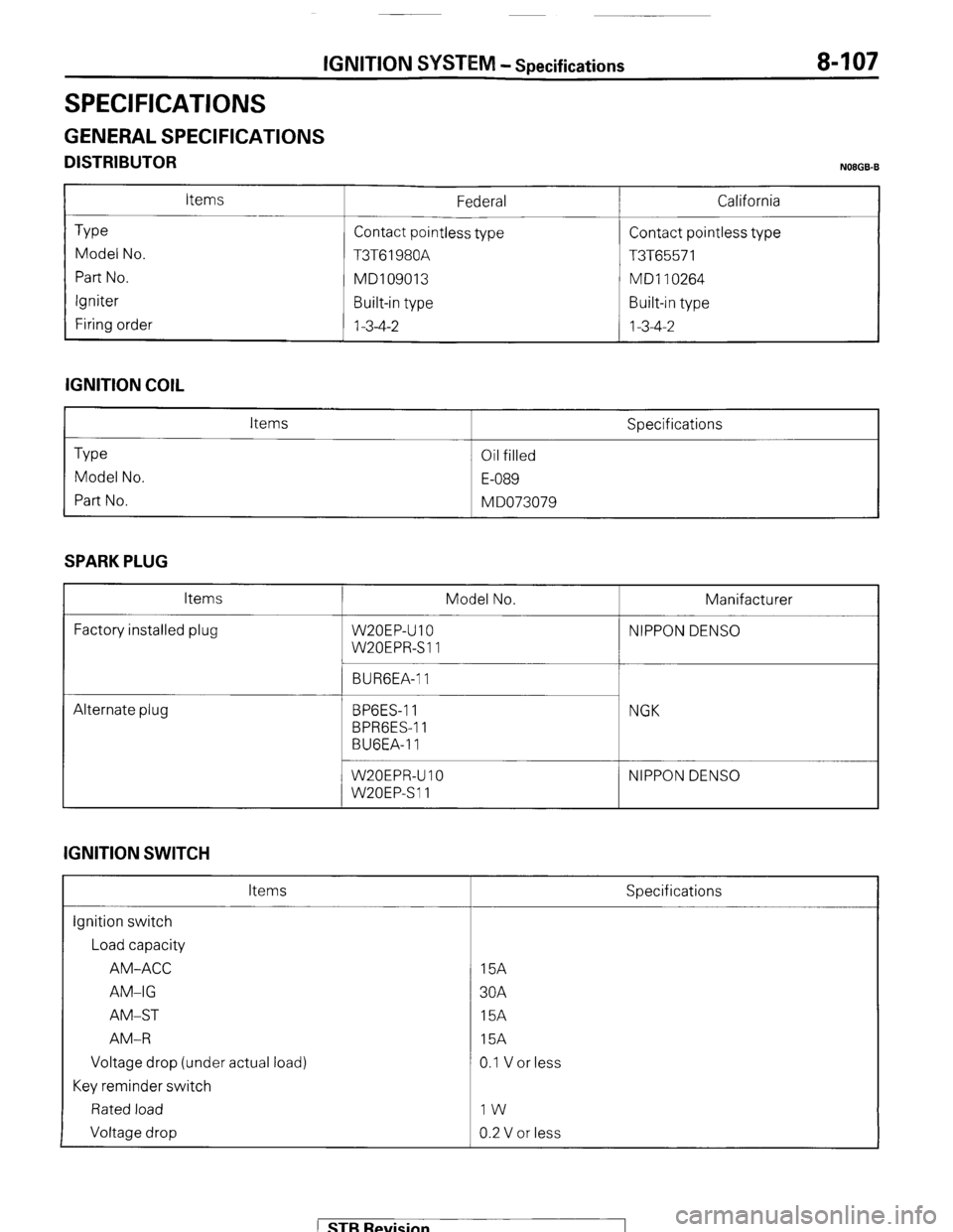
IGNITION SYSTEM - Specifications 8-107
SPECIFICATIONS
GENERAL SPECIFICATIONS
DISTRIBUTOR N08GB.B
Type
Model No.
Part No.
Igniter
Firing order Items Federal
Contact pointless type
T3T61980A
MD109013
Built-in type
1-3-4-2 California
Contact pointless type
T3T65571
MD1 10264
Built-in type
1-3-4-2
IGNITION COIL
Type
Model No.
Part No. Items
Oil filled
E-089
M DO73079 Specifications
SPARK PLUG
Items
Factory installed plug Model No. Manifacturer
W20EP-U 10 NIPPON DENS0
W20EPR-Sll
BURGEA-1 1
Alternate plug BPGES-1 1
BPRGES-1 1
BUGEA-11 NGK
W20EPR-U IO
W20EPSll NIPPON DENS0
IGNITION SWITCH
Items
ignition switch
Load capacity
AM-ACC
AM-IG
AM-ST
AM-R
Voltage drop (under actual load)
Key reminder switch
Rated load
Voltage drop Specifications
15A
30A
15A
15A
0.1 V or less
IW
0.2 V or less
) STB Revision
Page 128 of 284
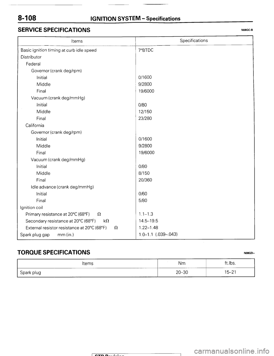
8408 IGNITION SYSTEM - Specifications
SERVICE SPECIFICATIONS
N08GC-B
Items Specifications
Basic ignition timing at curb idle speed 7”BTDC
Distributor
Federal
Governor (crank deghpm)
Initial O/l 600
Middle 1 9/2800
Final 1 g/6000
Vacuum (crank deg/mmHg)
Initial
O/80
Middle 12/I 50
Final 231280
California
Governor (crank deghpm)
initial O/l 600
Middle 912800
Final 1 g/6000
Vacuum (crank deg/mmHg)
Initial O/80
Middle 8/l 50
Final 201360
Idle advance (crank deg/mmHg)
Initial O/60
Final 5180
Ignition coil
Primary resistance at 20°C (68°F) R 1.1-1.3
Secondary resistance at 20°C (68°F) k0 14.5-19.5
External resistor resistance at 20°C (68°F) 1R 1.22-1.48
Spark plug gap mm (in.) 1.0-I .I (.039-,043)
TORQUE SPECIFICATIONS
Items Nm
NOBGD-
ft.lbs.
Spark plug 20-30 15-21
1 STB Revision