bulb MITSUBISHI MONTERO 1987 1.G Workshop Manual
[x] Cancel search | Manufacturer: MITSUBISHI, Model Year: 1987, Model line: MONTERO, Model: MITSUBISHI MONTERO 1987 1.GPages: 284, PDF Size: 14.74 MB
Page 34 of 284
8-14 WIRING HARNESS - Troubleshooting
1680222
Changeover knob 1680224
1680225 1
1680226
INSPECTION
1. Visual and aural checks
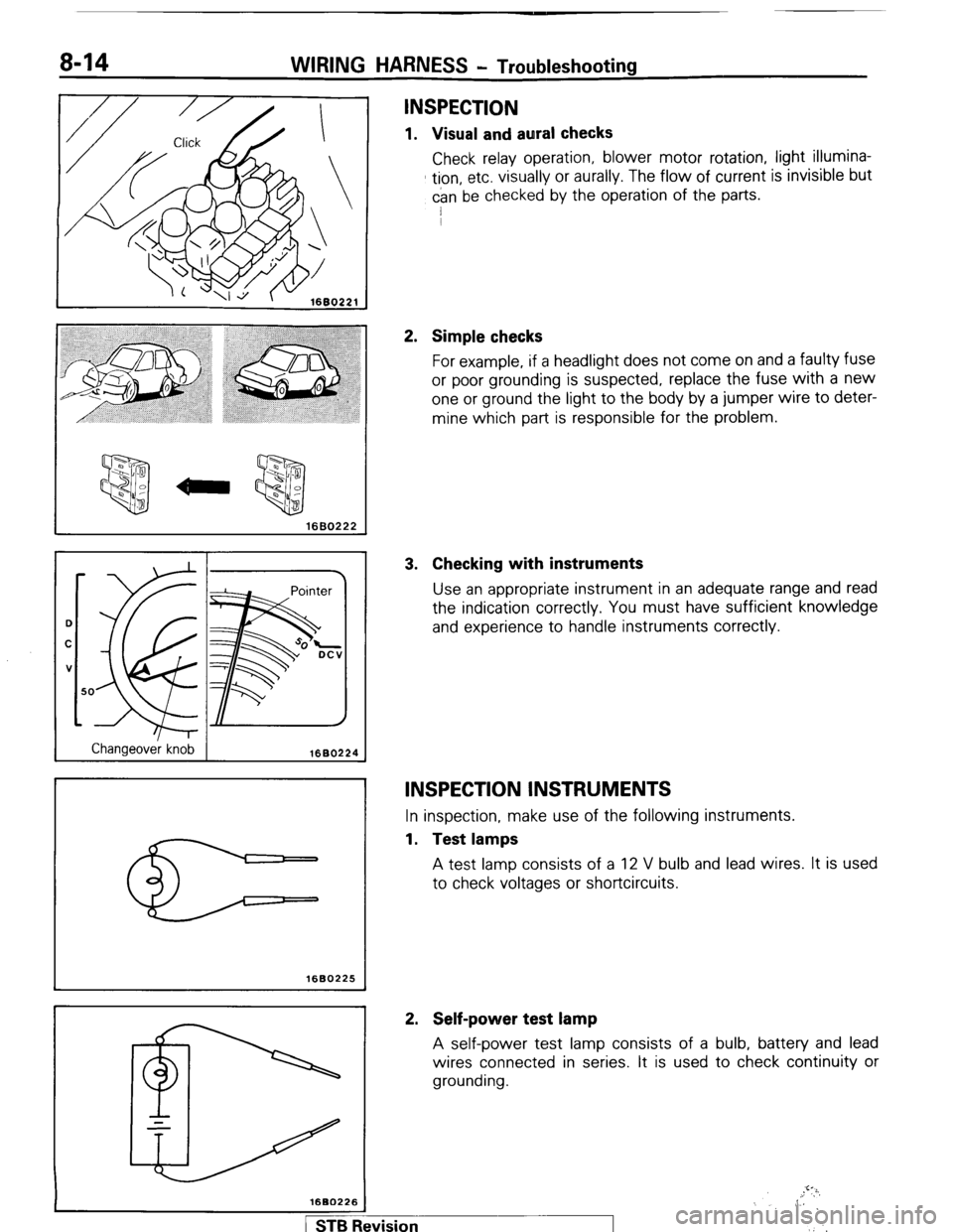
Check relay operation, blower motor rotation, light illumina-
tion, etc. visually or aurally. The flow of current is invisible but
can be checked by the operation of the parts.
I
2. Simple checks
For example, if a headlight does not come on and a faulty fuse
or poor grounding is suspected, replace the fuse with a new
one or ground the light to the body by a jumper wire to deter-
mine which part is responsible for the problem.
3. Checking with instruments
Use an appropriate instrument in an adequate range and read
the indication correctly. You must have sufficient knowledge
and experience to handle instruments correctly.
INSPECTION INSTRUMENTS
In inspection, make use of the following instruments.
1. Test lamps
A test lamp consists of a 12 V bulb and lead wires. It is used
to check voltages or shortcircuits.
2. Self-power test lamp
A self-power test lamp consists of a bulb, battery and lead
wires connected in series. It is used to check continuity or
grounding.
,.!‘?i,
,, 6
,‘.’
1 STB Revision
Page 46 of 284
8-26 WIRING HARNESS - HOW to Read Wiring Diagrams
SYMBOLIC MARKS
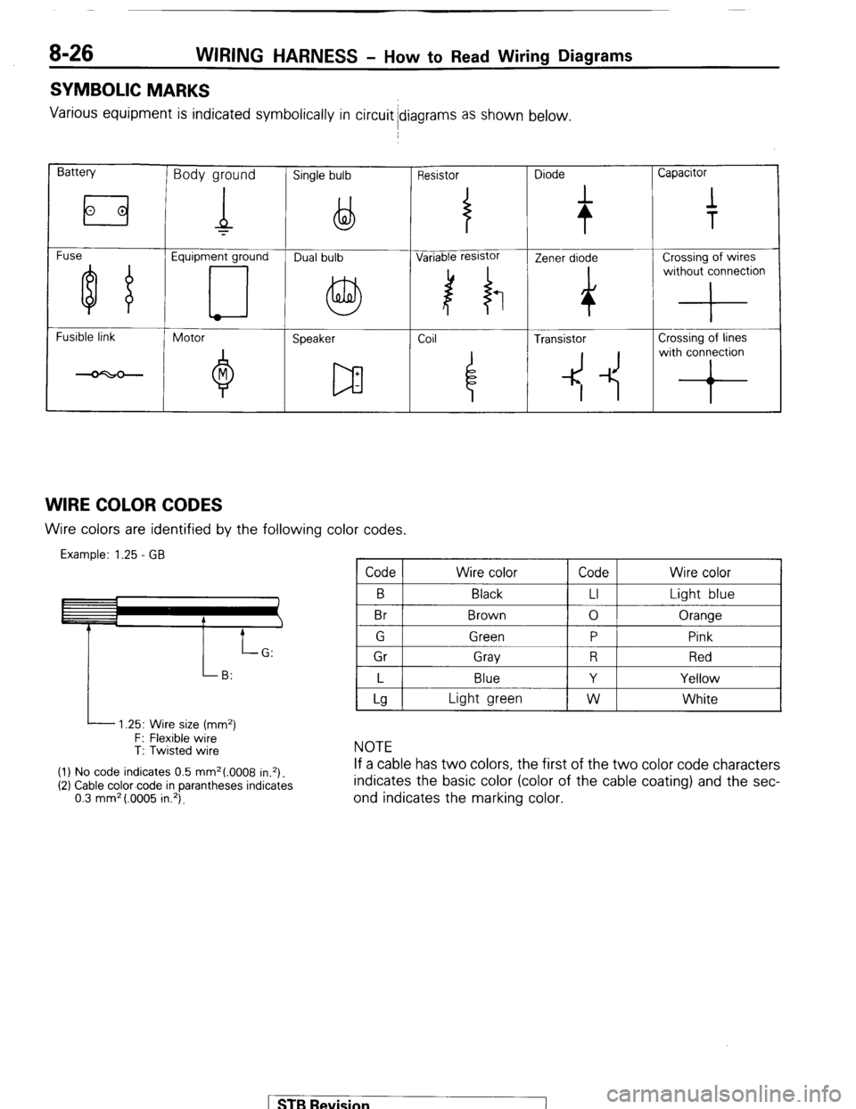
Various equipment is indicated symbolically in circuit idiagrams as shown below.
Battery Body ground Single bulb Resistor Diode Capacitor
Fuse Equipment ground
Fusible link
Motor
Speaker Coil ~
4 Transistor Crossing of lines
4 -1~ with conron
WIRE COLOR CODES Wire colors are identified by the following color codes.
Example: 1.25 - GB Code Wire color Code Wire color
B
Br Black
Brown LI
0 Light blue
Oranqe
I P
i 1 Gr 1 Grav 1 R 1 Red I
I L I Blue
I Y I Yellow I
L 1.25: Wire size (mm2)
F: Flexible wire
T: Twisted wire
(1) No code indicates 0.5 mm2(.0008 in.*).
(2) Cable color-code in parantheses indicates
0.3 mm* (.0005 in.‘).
Lg Light green W White
NOTE
If a cable has two colors, the first of the two color code characters
indicates the basic color (color of the cable coating) and the sec-
ond indicates the marking color.
STB Revision
Page 147 of 284
METERS AND GAUGES -Troubleshooting 8-127
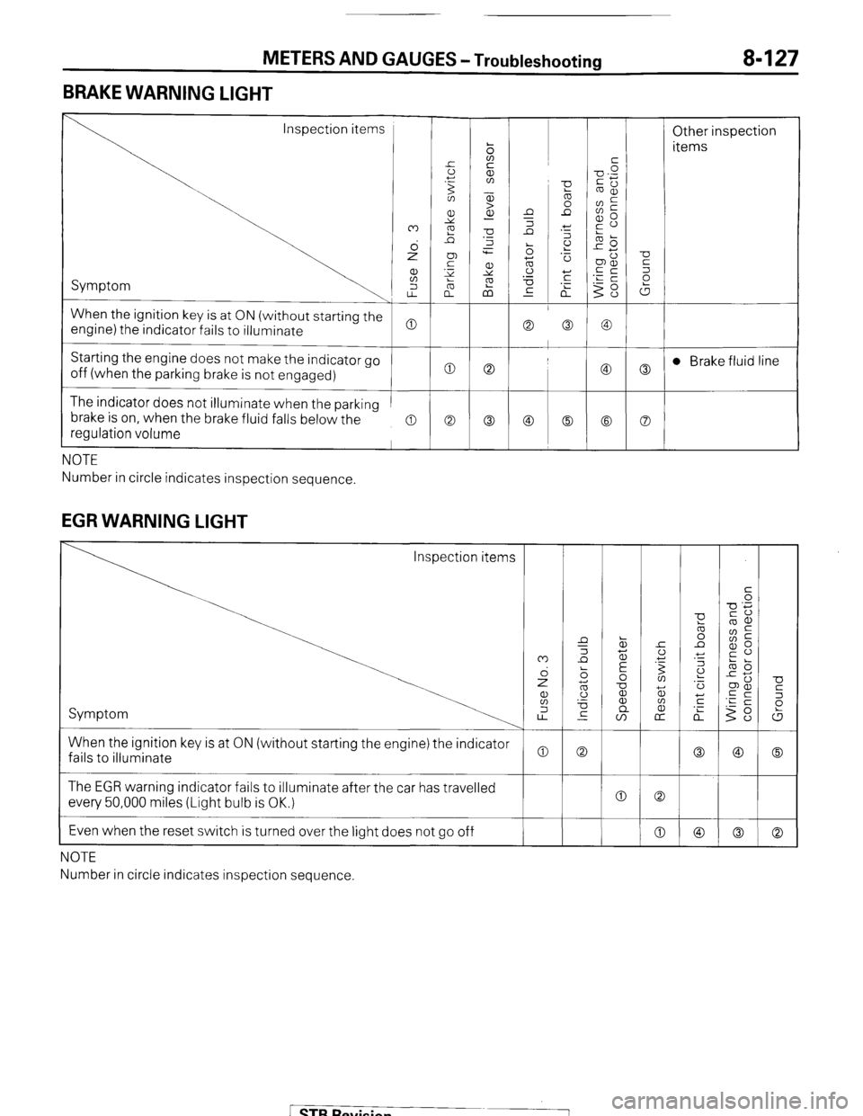
BRAKE WARNING LIGHT
Inspection items
Other inspection
items
Symptom
When the ignition key is at ON (without starting the
engine) the indicator fails to illuminate
Starting the engine does not make the indicator go
off (when the parking brake is not engaged) t 0 0
c
The indicator does not illuminate when the parking
brake is on, when the brake fluid falls below the
regulation volume
a a Co
NOTE
Number in circle indicates inspection sequence.
EGR WARNING LIGHT
U
5
P
W
0
Co When the ignition key is at ON (without starting the engine) the indicator
fails to illuminate
0 The EGR warning indicator fails to illuminate after the car has travelled
every 50,000 miles (Light bulb is OK.)
Even when the reset switch is turned over the light does not go off 0 0
0
I
NOTE
Number in circle indicates inspection sequence.
[ STB Revision
Page 162 of 284
8-142 METERS AND GAUGES - EGR Warning System
EGR WARNING SYSTEM
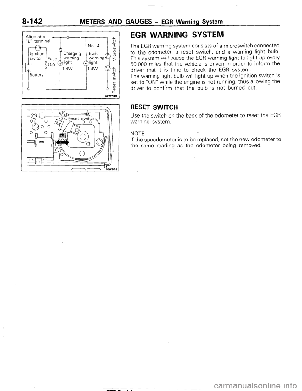
The EGR warning system consists of a microswitch connected
to the odometer, a reset switch, and a warning light bulb.
This system will cause the EGR warning light to light up every
50,000 miles that the vehicle is driven in order to inform the
driver that it is time to check the EGR system.
The warning light bulb will light up when the ignition switch is
set to “ON” while the engine is not running, thus allowing the
driver to confirm that the bulb is not burned out.
RESET SWITCH
Use the switch on the back of the odometer to reset the EGR
warning system.
NOTE
If the speedometer is to be replaced, set the new odometer to
the same reading as the odometer being, removed.
1 STB Revision
Page 270 of 284
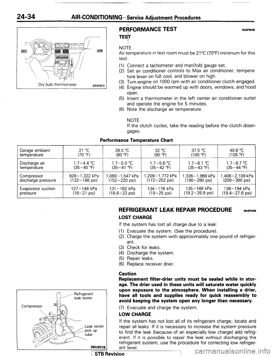
24-34 AIR-CONDITIONING-Service Adiustment Procedures
r---- :
:ES
Dry bulb therr&neter
2OW825
PEAFORMANCE TEST
TESI N24FWAB NOTE
Air temperature in test room must be 21°C (70°F) minimum for this
test.
(1) Connect a tachometer and manifold gauge set.
(2) Set air conditioner controls to Max air conditioner, tempera-
ture lever on full cool, and blower on high.
(3) Turn engine on 1000 rpm with air conditioner clutch engaged.
(4) Engine should be warmed up with doors, windows, and hood
open.
(5) Insert a thermometer in the left center air conditioner outlet
and operate the engine for 5 minutes.
(6) Note the discharge air temperature.
NOTE
If the clutch cycles, take the reading before the clutch disen-
gages.
Performance Temperature Chart Garage ambient
temperature
21 “C 26.5 “C 32 “C 37.5 “C 40.6 “C (70 “F) (80 “F) (90 “F) (100 “F) (I 05 “F)
Discharge air
temperature
Compressor
discharge pressure
Evaporator suction
pressure
1.7-4.4 “C 1.7-5.0 “C 1.7-5.6 “C 1.7-6.1 “C 1.7-6.7 “C (35-40 “F) (35-41 “F) (35-42 “F) (35-43 “F) (35-44 “F)
928- 1,322 kPa 1.069-1.547 kPa 1,209-1,772 kPa 1,336-1,969 kPa 1,406-2,109 kPa
(132-188 psi) (152-220 psi) (172-252 psi) (190-280 psi) (200-300 psi)
127-148 kPa
131-162 kPa 134-176 kPa 135- 188 kPa 136-194 kPa
(18-21 psi) (18.6-23 psi) (19-25 psi) (19.2-26.8 psi) (19.4-27.6 psi)
REFRIGERANT LEAK REPAIR PROCEDURE N24FnAB
LOST CHARGE If the system has lost all charge due to a leak:
(1) Evacuate the system. (See the procedure).
(2) Charge the system with approximately one pound of refriger-
ant.
(3) Check for leaks.
(4) Discharge the system.
(5) Repair leaks.
(6) Replace receiver drier.
Caution
Refrigerant
leak tester
Replacement filter-drier units must be sealed while in stor-
age. The drier used in these units will saturate water quickly
upon exposure to the atmosphere. When installing a drier,
have all tools and supplies ready for quick reassembly to
avoid keeping the system open any longer than necessary. (7) Evacuate and charge the system.
LOW CHARGE If the system has not lost all of its refrigerant charge; locate and
tester repair all leaks. If it is necessary to increase the system pressure
up to find the leak (because of an especially low charge) add refrig-
erant. If it is possible to repair the leak without discharging the
refrigerant system, use the procedure for correcting low refriger-
2OUO316 ant level.
1 STB Revision