sensor MITSUBISHI MONTERO 1987 1.G User Guide
[x] Cancel search | Manufacturer: MITSUBISHI, Model Year: 1987, Model line: MONTERO, Model: MITSUBISHI MONTERO 1987 1.GPages: 284, PDF Size: 14.74 MB
Page 131 of 284
IGNITION SYSTEM - Service Adjustment Procedures 8-111
SERVICE ADJUSTMENT PROCEDURES
CHECKING IGNITION TIMING NOEGIBA
IGNITION TIMING ADJUSTMENT
Adjustment conditions:
Coolant temperature: 80-90°C (170-I 90°F)
Lights and all accessories: Off
Transmission: N (Neutral)
1. Connect tachometer and timing light.
2. Start eng.ine and run at curb idle speed.
I
Curb idle speed rpm
First 500 km
(300 mile)
After 500 km
(300 mile)
725';;;
800 ?I00 3. To make adjustment at high altitude, disconnect pressure
sensor connector before stopping engine. Then restart
engine and run it at curb idle speed.
4. Check basic ignition timing and adjust if necessary.
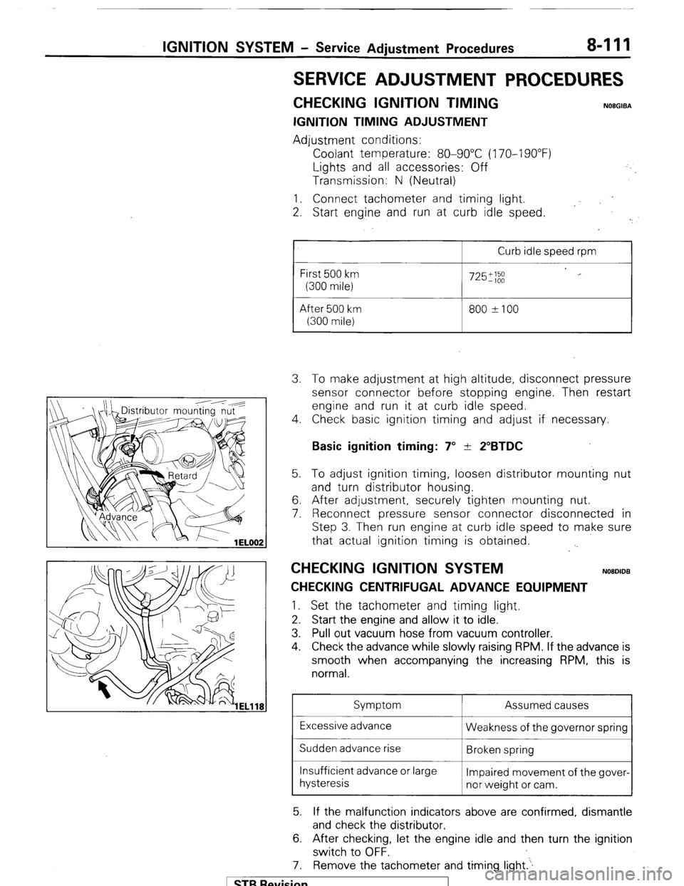
Basic ignition timing: 7” + 2”BTDC 5. To adjust ignition timing, loosen distributor mounting nut
and turn distributor housing.
6. After adjustment, securely tighten mounting nut.
7. Reconnect pressure sensor connector disconnected in
Step 3. Then run engine at curb idle speed to make sure
that actual ignition timing is obtained.
. .
CHECKING IGNITION SYSTEM NOBDIDB
CHECKING CENTRIFUGAL ADVANCE EQUIPMENT 1.
Set the tachometer and timing light.
2. Start the engine and allow it to idle.
3. Pull out vacuum hose from vacuum controller.
4. Check the advance while slowly raising RPM. If the advance is
smooth when accompanying the increasing RPM, this is
normal.
Symptom Assumed causes
Excessive advance
Weakness of the governor spring
Sudden advance rise
Broken spring
Insufficient advance or large
Impaired movement of the gover-
hysteresis
nor weight or cam.
5. If the malfunction indicators above are confirmed, dismantle
and check the distributor.
6. After checking, let the engine idle and then turn the ignition
switch to OFF.
7. Remove the tachometer and timing light.‘.
1 STB Revision
Page 228 of 284
8-208 AUTO
ATIC FREE-WHEELING HUB INDICAUOR SYSTEM - General Information
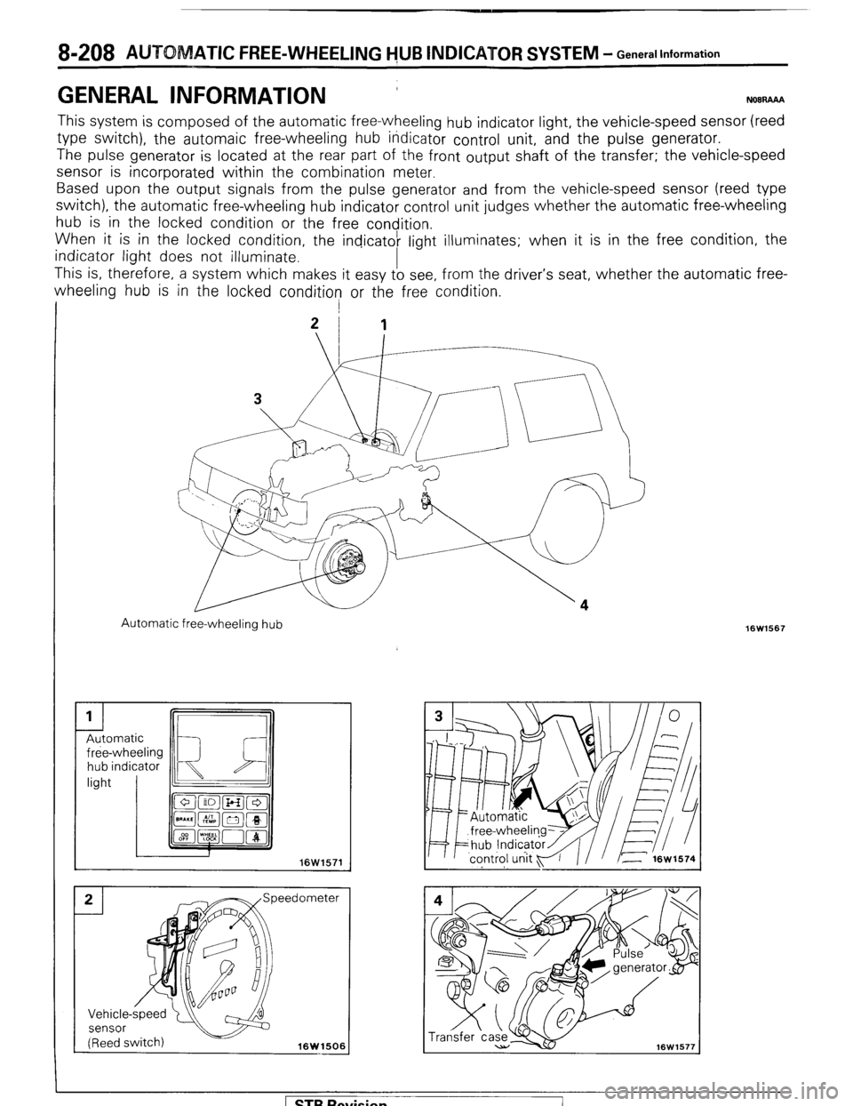
GENERAL INFORMATION ’ N08RAAA
This system is composed of the automatic free-wheeling hub indicator light, the vehicle-speed sensor (reed
type switch), the automaic free-wheeling hub itidicator control unit, and the pulse generator.
The pulse
generator is located at the rear part of the front output shaft of the transfer; the vehicle-speed
sensor is incorporated within the combination meter.
Based upon the output signals from the pulse generator and from the vehicle-speed sensor (reed type
switch), the automatic free-wheeling hub indicator control unit judges whether the automatic free-wheeling
hub is in the locked condition or the free condition.
When it is in the locked condition, the indicatok light
illuminates; when it is in the free condition, the
indicator light does not illuminate.
This is, therefore, a system which makes it easy to see, from the driver’s seat, whether the automatic free-
wheeling hub is in the locked condition or the free condition.
I j
21 1
Automatic free-wheeling hub
hub indicator
16W1506 16W1567
1 STB Revision
Page 229 of 284
AUTOMATIC FREE-WHEELING HUB INDICATOR SYSTEM - General Information 8-209
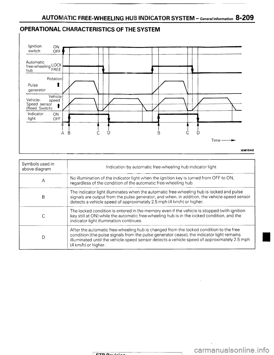
OPERATIONAL CHARACTERISTICS OF THE SYSTEM
Time-----w
16W1548 Indication by automatic free-wheeling hub indicator light
No illumination of the indicator light when the ignition key is turned from OFF to ON,
regardless of the condition of the automatic free-wheeling hub.
The indicator light illuminates when the automatic free-wheeling hub is locked and pulse
signals are output from the pulse generator, and when, in addition, the vehicle-speed sensor
detects a vehicle speed of approximately 2.5 mph (4 km/h) or higher.
The locked condition is entered in the memory even if the vehicle is stopped (with ignition
key still at ON) while the automatic free-wheeling hub is in the locked condition, and the
indicator light illumination continues.
After the automatic free-wheeling hub is changed from the locked condition to the free
condition (the pulse signals from the pulse generator cease), the indicator light remains
illuminated until the vehicle-speed sensor detects a vehicle speed of approximately 2.5 mph
(4 km/h) or higher. Symbols used in
above diagram
A
B
C
D
1 STB Revision
Page 230 of 284
8-210 AUTOMATIC FREE-WHEELING HUB INDICATOR SYSTEM - General Information
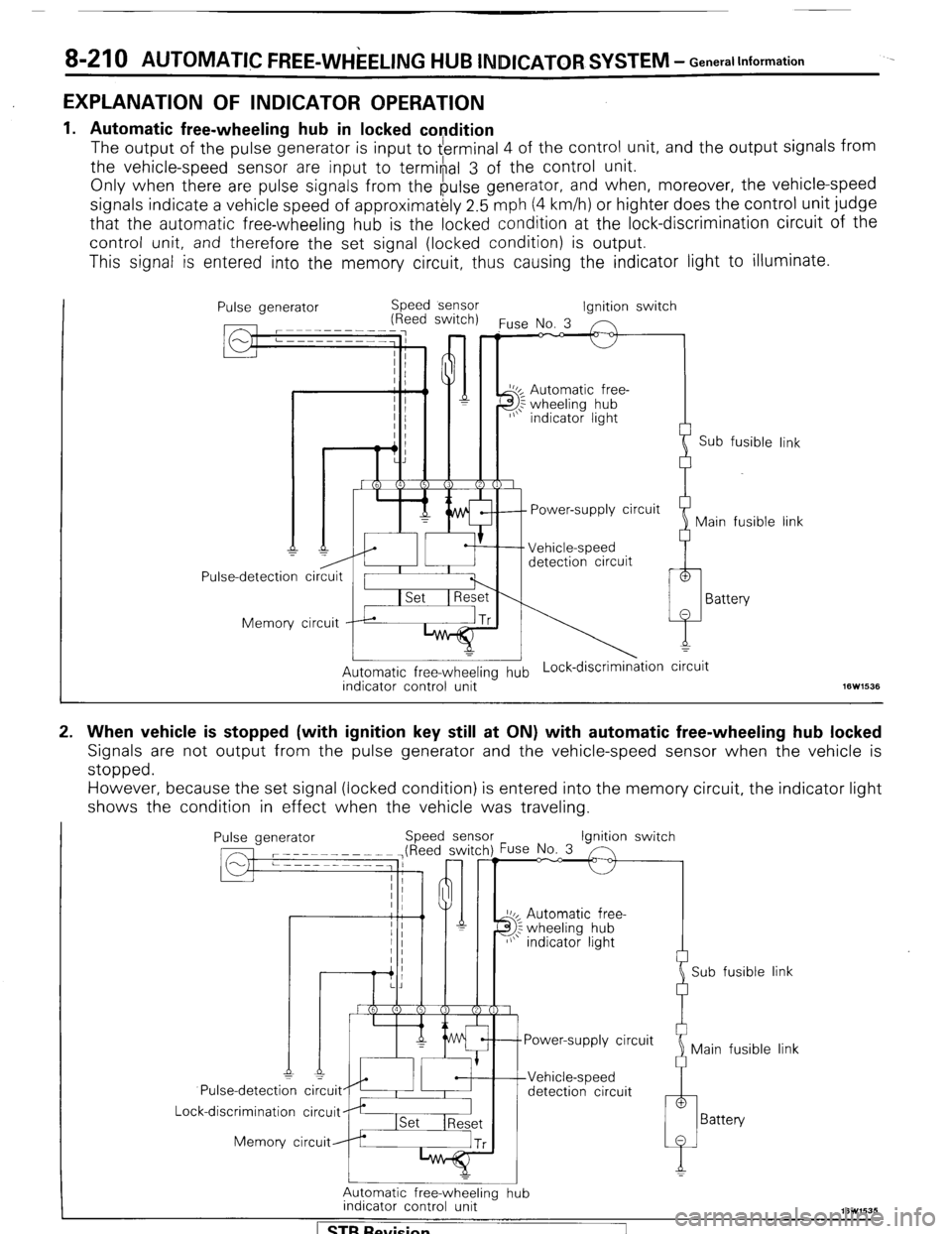
EXPLANATION OF INDICATOR OPERATION
.
1.
2. Automatic free-wheeling hub in locked condition
The
output of the pulse generator is input to $ertninal 4 of the control unit, and the output signals from
the vehicle-speed sensor are input
to termi#al 3 of the control unit.
Only when there are pulse signals from the pulse generator, and when, moreover, the vehicle-speed
signals indicate a vehicle speed of approximatkly 2.5 mph (4 km/h) or highter does the control unit judge
that the automatic free-wheeling hub is the locked condition at the lock-discrimination circuit of the
control unit, and therefore the set signal (locked condition) is output.
This signal is entered into the memory circuit, thus causing the indicator light to illuminate.
Pulse generator Speed sensor
(Reed switch)
Pulse-detection circuit / I I
Memory circuit rp*
I
Automatic free-wheeling hub Lock-discrimin&ion circuit
indicator control unit 16W1535 Ignition switch
‘use No. 3 n
J 2
I_
Power-supply circuit
Vehicle-speed
detection circuit 1
Sub fusible link 1
Main fusible link 1
)
1
Battery
When vehicle is stopped (with ignition key still at ON) with automatic free-wheeling hub locked
Signals are not output from the pulse generator and the vehicle-speed sensor when the vehicle is
stopped.
However, because the set signal (locked condition) is entered into the memory circuit, the indicator light
shows the condition in effect when the vehicle was traveling.
Pulse generator Speed sense
Pulse-detecti: ci~uit~~I~ #
Lock-discrimination circuit
Memory circuit ‘use No. 3 Ignition switch
10~ Automatic free-
3; wheeling hub
I/\’ indicator light
Sub fusible link
Power-supply circuit
Main fusible link
detection circuit
Automatic free-wheeling hub
indicator control unit
[ STB Revision
Page 231 of 284
AUTOMATIC FREE-WHEELING HUB INDICATOR SYSTEM - Generallnformation 8-211
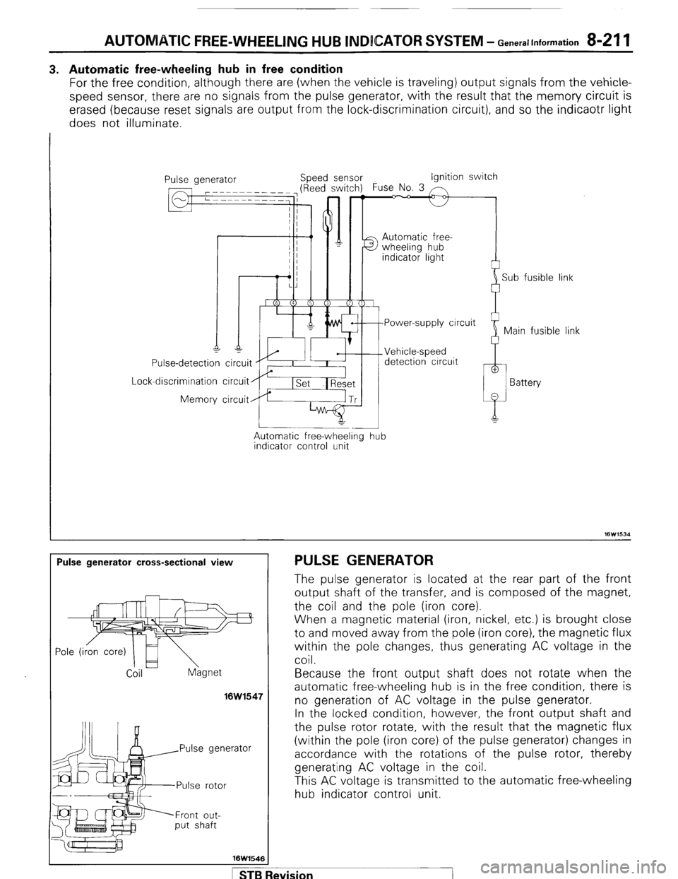
3. Automatic free-wheeling hub in free condition
For the free condition, although there are (when the vehicle is traveling) output signals from the vehicle-
speed sensor, there are no signals from the pulse generator, with the result that the memory circuit is
erased (because reset signals are output from the lock-discrimination circuit), and so the indicaotr light
does not illuminate.
I
Lock Use-detection
-discrimination
Memory ipeed sensor Ignition switch
Automatic free-
detection circuit
circuit
circuit
Automatic free-wheeling
indicator control unit -
hub i
Sub fusible link
link
Pulse generator cross-sectional view PULSE GENERATOR
Coil hgnet
16W1547
rator
Front out-
put shaft
16W1546 The pulse generator is located at the rear part of the front
output shaft of the transfer, and is composed of the magnet,
the coil and the pole (iron core).
When a magnetic material (iron, nickel, etc.) is brought close
to and moved away from the pole (iron core), the magnetic flux
within the pole changes, thus generating AC voltage in the
coil.
Because the front output shaft does not rotate when the
automatic free-wheeling hub is in the free condition, there is
no generation of AC voltage in the pulse generator.
In the locked condition, however, the front output shaft and
the pulse rotor rotate, with the result that the magnetic flux
(within the p o e I (’ Iron core) of the pulse generator) changes in
accordance with the rotations of the pulse rotor, thereby
generating AC voltage in the coil.
This AC voltage is transmitted to the automatic free-wheeling
hub indicator control unit.
STB Revision
Page 232 of 284
8-212 AUTOMATIC FREE-WHEELING HUB lNCDlCATOR SYSTEM - $%%60n’~at’on’
Speedometer
I
iensor Vehicle-speed
sensor
16W1506
12R0058
Circuit Diagram
16W153
SPECIFICATIONS
GENERAL SPECIFICATIONS VEHICLE-SPEED SENSOR (REED-TYPE SWITCH)
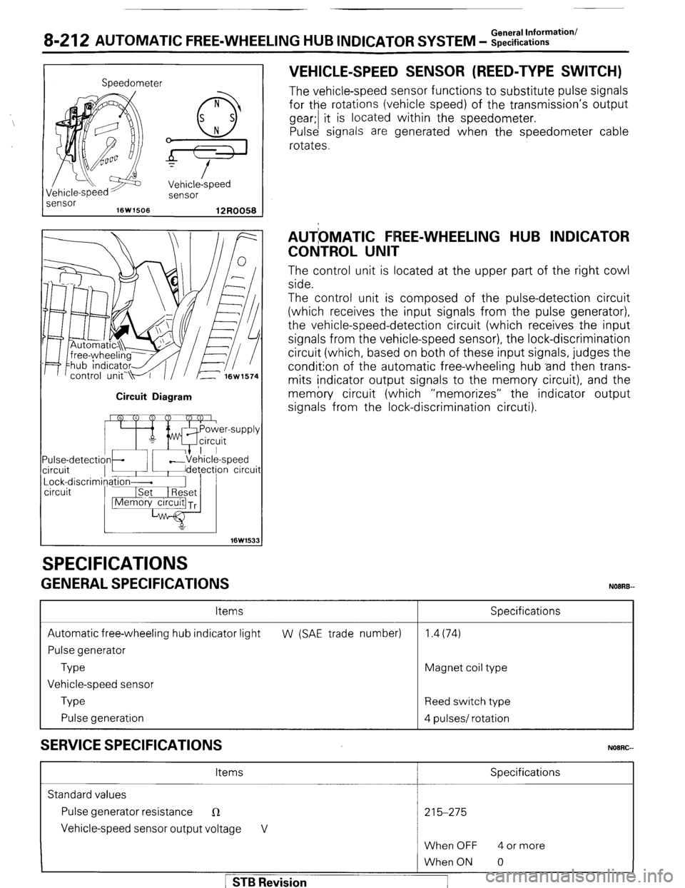
The vehicle-speed sensor functions to substitute pulse signals
for the rotations (vehicle speed) of the transmission’s output
gear;/ t i is located within the speedometer.
Pulse signals are generated when the speedometer cable
rotates.
AUTbMATlC FREE-WHEELING HUB INDICATOR
CONTROL UNIT
The control unit is located at the upper part of the right cowl
side.
The control unit is composed of the pulse-detection circuit
(which receives the input signals from the pulse generator),
the vehicle-speed-detection circuit (which receives the input
signals from the vehicle-speed sensor), the lock-discrimination
circuit (which, based on both of these input signals, judges the
condition of the automatic free-wheeling hub ‘and then trans-
mits indicator output signals to the memory circuit), and the
memory circuit (which “memorizes” the indicator output
signals from the lock-discrimination circuti).
Items
Automatic free-wheeling hub indicator light
Pulse generator
Type
Vehicle-speed sensor
Type
Pulse generation
SERVICE SPECIFICATIONS
Specifications
W (SAE trade number) 1.4(74)
Magnet coil type
Reed switch type
4 pulses/ rotation
NOORG-
Items Specifications
Standard values
Pulse generator resistance
R 215-275
Vehicle-speed sensor output voltage V
When OFF 4 or more 1 STB Revision
When ON 0
Page 236 of 284
8-216 AUTOMATIC FREE-WHEELING HUB INDICATOR SYSTEM - Control Unit
AUTOMATIC FREE-WHEELING HUB INDICATOR CONTROL UNIT
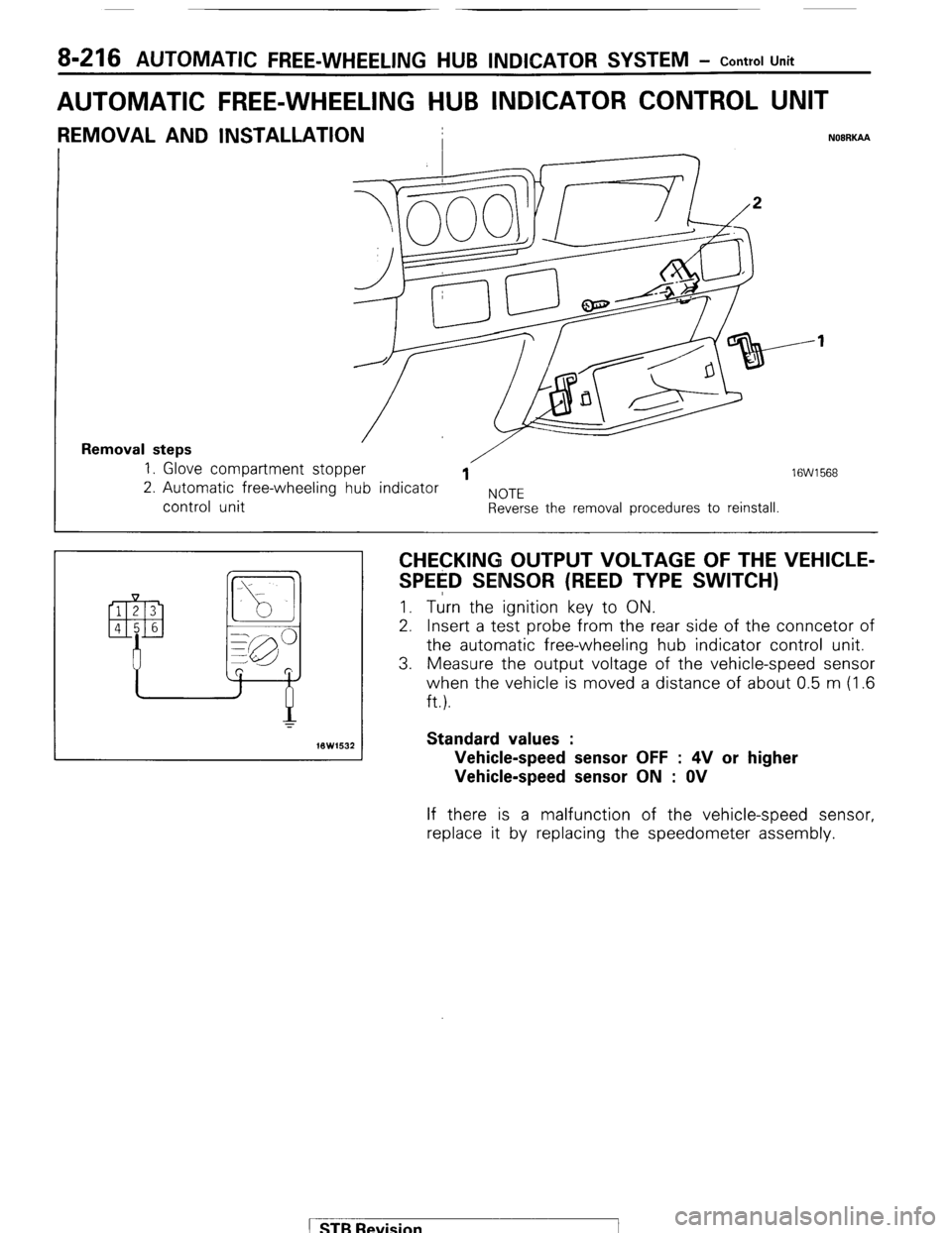
REMOVAL AND INSTALLATION
I NOBRKAA
Removal steps 1. Glove compartment stopper /
1 16W1568 2. Automatic free-wheeling hub indicator
NOTE control unit Reverse the removal procedures to reinstall.
CHECKING OUTPUT VOLTAGE OF THE VEHICLE-
SPE$D SENSOR (REED TYPE SWITCH) I. Turn the ignition key to ON.
2. Insert a test probe from the rear side of the conncetor of
the automatic free-wheeling hub indicator control unit.
3. Measure the output voltage of the vehicle-speed sensor
when the vehicle is moved a distance of about 0.5 m (1.6
ft.).
Standard values :
Vehicle-speed sensor OFF : 4V or higher
Vehicle-speed sensor ON : OV If there is a malfunction of the vehicle-speed sensor,
replace it by replacing the speedometer assembly.
( STB Revision
Page 256 of 284
24-20 AIR-CONDITION!NG-General Information
I
AIR-CONDITIONING SYSTEM COMPO
N24BBBB
Condenser MDuct, joint (Blower side)
oint (Heater unit
Condenser
2OWB31
Suction Pipe Receiver bracket side)
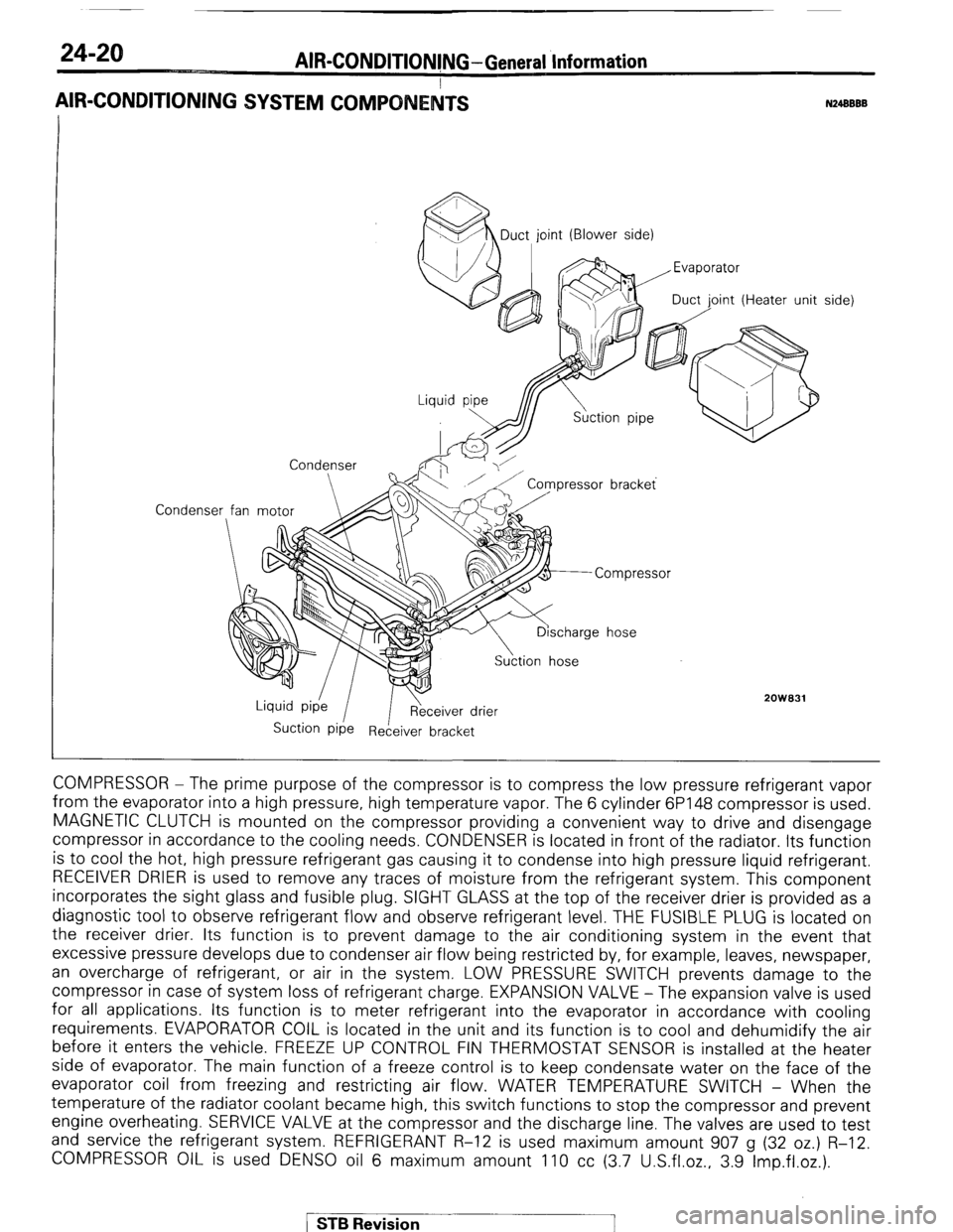
COMPRESSOR - The prime purpose of the compressor is to compress the low pressure refrigerant vapor
from the evaporator into a high pressure, high temperature vapor. The 6 cylinder 6P148 compressor is used.
MAGNETIC CLUTCH is mounted on the compressor providing a convenient way to drive and disengage
compressor in accordance to the cooling needs. CONDENSER is located in front of the radiator. Its function
is to cool the hot, high pressure refrigerant gas causing it to condense into high pressure liquid refrigerant.
RECEIVER DRIER is used to remove any traces of moisture from the refrigerant system. This component
incorporates the sight glass and fusible plug. SIGHT GLASS at the top of the receiver drier is provided as a
diagnostic tool to observe refrigerant flow and observe refrigerant level. THE FUSIBLE PLUG is located on
the receiver drier. Its function is to prevent damage to the air conditioning system in the event that
excessive pressure develops due to condenser air flow being restricted by, for example, leaves, newspaper,
an overcharge of refrigerant, or air in the system. LOW PRESSURE SWITCH prevents damage to the
compressor in case of system loss of refrigerant charge. EXPANSION VALVE - The expansion valve is used
for all applications. Its function is to meter refrigerant into the evaporator in accordance with cooling
requirements. EVAPORATOR COIL is located in the unit and its function is to cool and dehumidify the air
before it enters the vehicle. FREEZE UP CONTROL FIN THERMOSTAT SENSOR is installed at the heater
side of evaporator. The main function of a freeze control is to keep condensate water on the face of the
evaporator coil from freezing and restricting air flow. WATER TEMPERATURE SWITCH - When the
temperature of the radiator coolant became high, this switch functions to stop the compressor and prevent
engine overheating. SERVICE VALVE at the compressor and the discharge line. The valves are used to test
and service the refrigerant system. REFRIGERANT R-12 is used maximum amount 907 g (32 oz.) R-12.
COMPRESSOR OIL is used DENS0 oil 6 maximum amount 110 cc (3.7 U.S.fl.oz., 3.9 Imp.fl.oz.).
/ STB Revision