fuses MITSUBISHI MONTERO 1987 1.G Workshop Manual
[x] Cancel search | Manufacturer: MITSUBISHI, Model Year: 1987, Model line: MONTERO, Model: MITSUBISHI MONTERO 1987 1.GPages: 284, PDF Size: 14.74 MB
Page 1 of 284
Service Manual
MONTERO
1987 : Volume 2
FOREWORD
This Service Manual has been prepared with the
latest service information available at the time of
publication. It is subdivided into various group
categories and each section contains diagnosis,
disassembly, repair, and installation procedures
along with complete specifications and tightening
references. Use of this manual will aid in properly
performing any servicing necessary to maintain or
restore the high levels of performance and reliability
designed into these outstanding vehicles.
WE SUPPORT
VOLUNTARY TECHNICIAN
CERTIFICATION THROUGH
MITSUBISHI MOTOR SALES OF AMERICA. Inc.
Mitsubishi Motors corporation reserves the right to make changes in
design or to make additions to or improvements in its products without
imposing any obligations upon itself to install them on its products
previously manufactured.
I
GROUP/SECTION INDEX ‘kme-.
INTRODUCTION ..............................
Electrical ...........................................
Electrical System Parts
Location .........................................
Relays, Control Units, Sensors,
Fuses, Groundings
Inspection of Harness
Connector ......................................
Wiring Harness .............................
Charging System ..........................
Starting System ............................
Ignition System .............................
Meters and Gauges ......................
Lighting System .............................
Wiper and Washer System ..........
Horn ...............................................
Accessory ......................................
Audio System ................................
Back Door Window Defogger ......
Automatic Free-wheeling Hub
Indicator System ..........................
Heaters and Air-conditioning .........
Heaters ..........................................
Air-conditioning ............................
**, For Engine Chassis & Body refer to
0 1986 Mitsubishi Motors Corporation Printed in Japan
Page 11 of 284
INTRODUCTION - Precautions Before Service 11
I
OOY63:
oOY58S IOA 15A
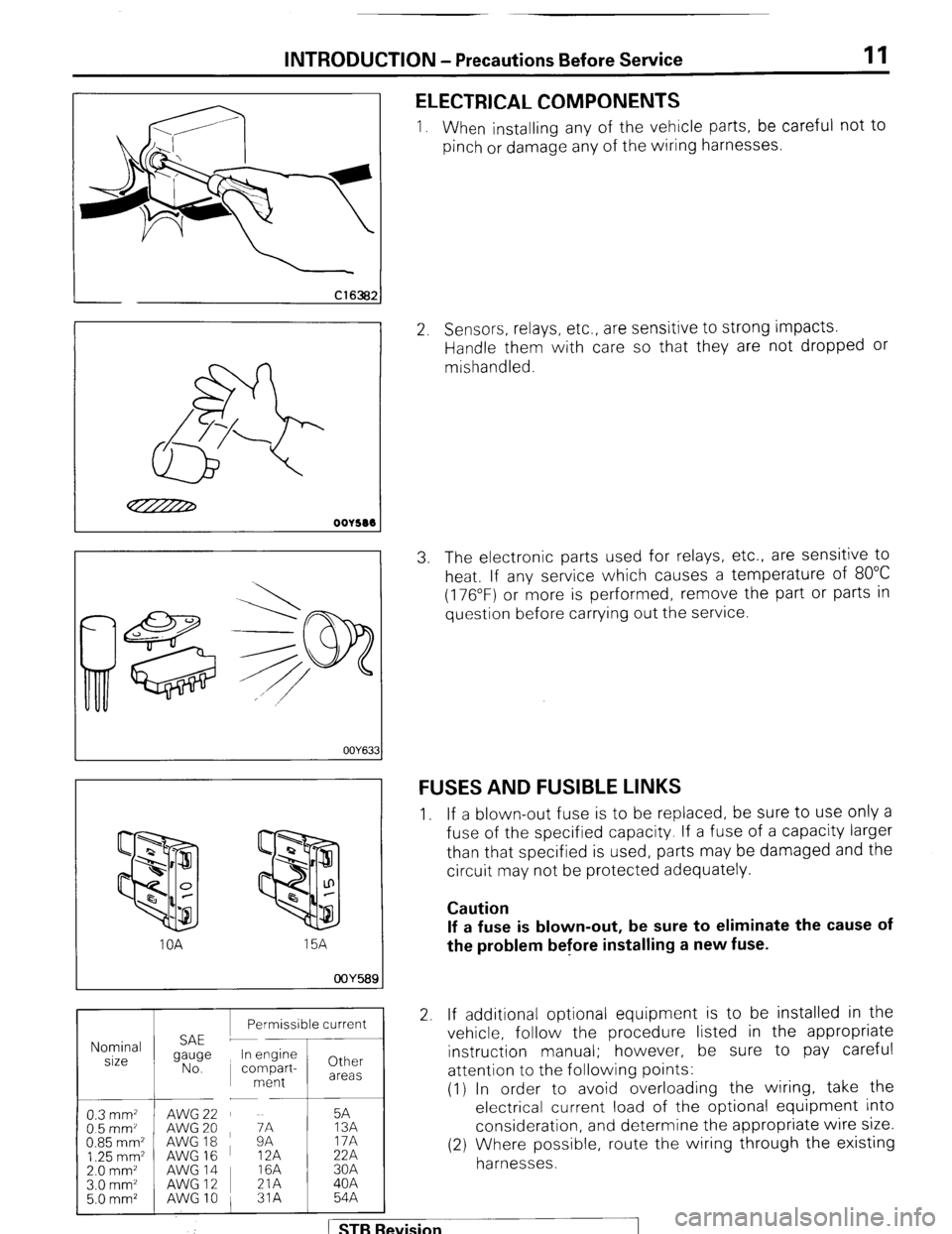
1 Permissible current 1
Nominal
size
0.3 mm2 AWG22 5A
05mm’ AWG 20
AWG18 ~ zi 13A
0.85 mm2 17A
1.25 mm2 AWG 16 12A 22A
2.0 mm2 AWG14 I 16A 30A
ELECTRICAL COMPONENTS
1. When installing any of the vehicle parts, be careful not to
pinch or damage any of the wiring harnesses.
2. Sensors, relays, etc., are sensitive to strong impacts.
Handle them with care so that they are not dropped or
mishandled.
3. The electronic parts used for relays, etc., are sensitive to
heat, If any service which causes a temperature of 80°C
(176°F) or more is performed, remove the part or parts in
question before carrying out the service.
FUSES AND FUSIBLE LINKS
1. If a blown-out fuse is to be replaced, be sure to use only a
fuse of the specified capacity. If a fuse of a capacity larger
than that specified is used, parts may be damaged and the
circuit may not be protected adequately.
Caution
If a fuse is blown-out, be sure to eliminate the cause of
the problem before installing a new fuse.
2 If additional optional equipment is to be installed in the
vehicle, follow the procedure listed in the appropriate
instruction manual; however, be sure to pay careful
attention to the following points:
(1) In order to avoid overloading the wiring, take the
electrical current load of the optional equipment into
consideration, and determine the appropriate wire size.
(2) Where possible, route the wiring through the existing
harnesses.
I Revision
Page 26 of 284
ELECTRICAL SYSTEM PARTS LOCATION - Fusible Link and Fuse
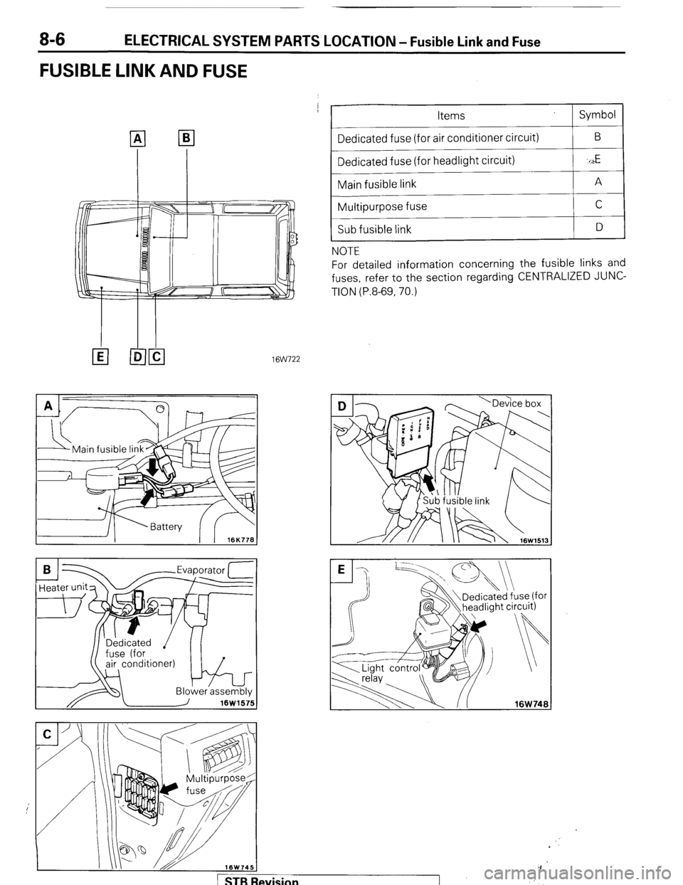
FUSIBLE LINK AND FUSE
--
Items
Dedicated fuse (for air conditioner circuit)
Dedicated fuse (for headlight circuit)
Main fusible link
Multipurpose fuse
Sub fusible link
NOTE Symbol
B
‘I
E
A
C
D
For detailed information concerning the fusible links and
fuses, refer to the section regarding CENTRALIZED JUNC-
TION (P.8-69, 70.)
16W722
-Evaoorator 1
/ STBI levision
Page 37 of 284
Normal close INC) type
Deenergized state
Energized state
I
WIRING HARNESS - Troubleshooting 8-17
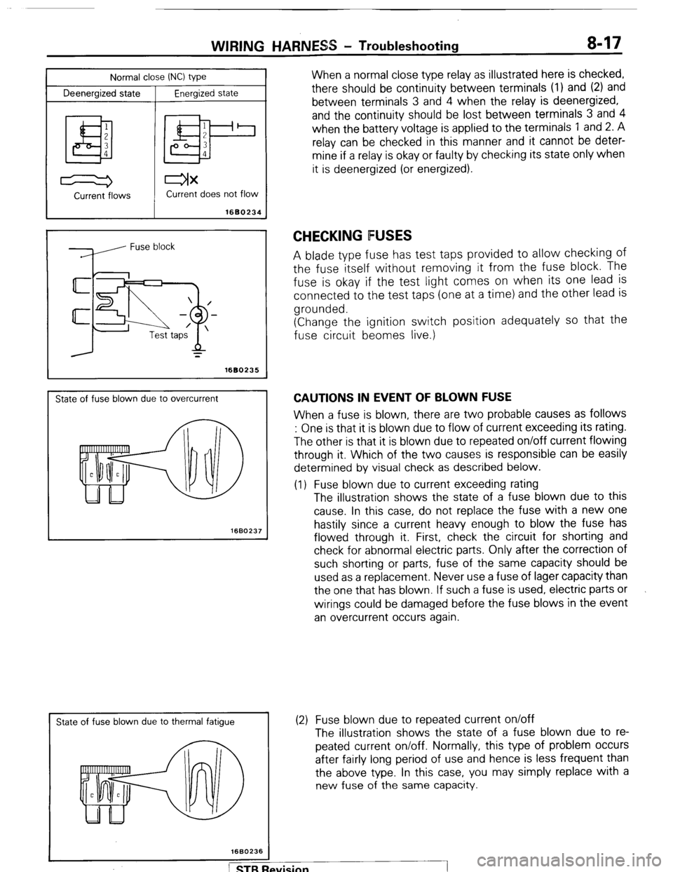
When a normal close type relay as illustrated here is checked,
there should be continuity between terminals (1) and (2) and
between terminals 3 and 4 when the relay is deenergized,
and the continuity should be lost between terminals 3 and 4
when the battery voltage is applied to the terminals 1 and 2. A
relay can be checked in this manner and it cannot be deter-
mine if a relay is okay or faulty by checking its state only when
it is deenergized (or energized).
Current -flows Current does not flow
1680234
=
1680235
State of fuse blown due to overcurrent
1660237
I
State of fuse blown due to thermal fatigue
CHECKING FUSES
A blade type fuse has test taps provided to allow checking of
the fuse itself without removing it from the fuse block. The
fuse is okay if the test light comes on when its one lead is
connected to the test taps (one at a time) and the other lead is
grounded.
(Change the ignition switch position adequately so that the
fuse circuit beomes live.)
CAUTIONS IN EVENT OF BLOWN FUSE
When a fuse is blown, there are two probable causes as follows
: One is that it is blown due to flow of current exceeding its rating.
The other is that it is blown due to repeated on/off current flowing
through it. Which of the two causes is responsible can be easily
determined by visual check as described below.
(1) Fuse blown due to current exceeding rating
The illustration shows the state of a fuse blown due to this
cause. In this case, do not replace the fuse with a new one
hastily since a current heavy enough to blow the fuse has
flowed through it. First, check the circuit for shorting and
check for abnormal electric parts. Only after the correction of
such shorting or parts, fuse of the same capacity should be
used as a replacement. Never use a fuse of lager capacity than
the one that has blown. If such a fuse is used, electric parts or
wirings could be damaged before the fuse blows in the event
an overcurrent occurs again.
(2) Fuse blown due to repeated current on/off
The illustration shows the state of a fuse blown due to re-
peated current on/off. Normally, this type of problem occurs
after fairly long period of use and hence is less frequent than
the above type. In this case, you may simply replace with a
new fuse of the same capacity.
Page 43 of 284
WIRING HARNESS - HOW BO Read Wiring Diagrams 8-23
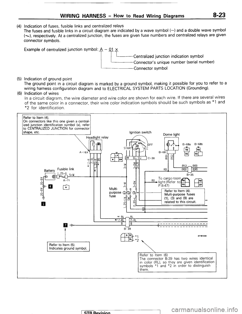
(4) Indication of fuses, fusible links and centralized relays
The fuses and fusible links in a circuit diagram are indicated by a wave symbol (-) and a double wave symbol
(~1, respectively. At a centralized junction, the fuses are given fuse numbers and centralized relays are given
connector symbols.
Example of centralized junction symbol: A - 01 x
Centralized junction indication symbol
Connector’s unique number (serial number)
Connector symbol
(5) Indication of ground point
The ground point in a circuit diagram is marked by a ground symbol, making it possible for you to refer to a
wiring harness configuration diagram and to ELECTRICAL SYSTEM PARTS LOCATION (Grounding).
(6) Indication of wires
In a circuit diagram, the wire diameter and wire color are shown for each wire. If there are several wires
of the same color in a connector, their wire color indication symbols should be such symbols as “I and
“2 for identification.
On connectors like this one given a central-
to CENTRALIZED JUNCTION for connector
1 shaoe. etc.
-I Headlight relay ignition switch
Dome light
I II I B-35 B-68b
P:8-47)
IEU
I ’ 2 I
RL
2-RL
0 III- BI B -----____________
L - - - - - _ _ _ _ _ __ _ _ _ _ _
B-39
Refer to Item (5).
Refer to Item (6)
The connector B-39 has two wires identical
in color (RL), so they are given identification
symbols *I and *2 in order to distinguish
them. 1 ST6 Revision
Page 95 of 284
CHARGING SYSTEM -Troubleshooting 8-75
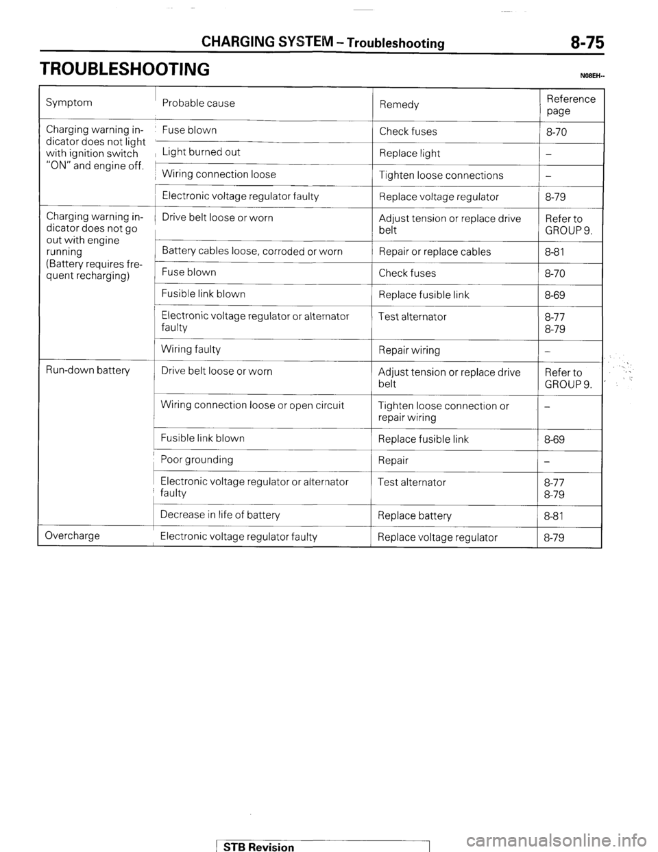
TROUBLESHOOTING
NOBEH-
Symptom Probable cause
Remedy Reference
we
Charging warning in- Fuse blown
dicator does not light
with ignition switch Light burned out
“ON” and engine off. 1
1 Wiring connection loose Check fuses
Replace light
Tighten loose connections 8-70
-
-
Charging warning in-
dicator does not go
out with engine
running
(Battery requires fre-
quent recharging)
L
t
Run-down battery
c
Electronic voltage regulator faulty
Drive belt loose or worn
Battery cables loose, corroded or worn
Fuse blown
Fusible link blown
Electronic voltage regulator or alternator
faulty
Wiring faulty
Drive belt loose or worn
Wiring connection loose or open circuit
Fusible link blown Replace voltage regulator
Adjust tension or replace drive
belt
Repair or replace cables
Check fuses
Replace fusible link
Test alternator
Repair wiring
Adjust tension or replace drive
belt
Tighten loose connection or
repair wiring
Replace fusible link 8-79
Refer to
GROUPS.
8-8 1
8-70
8-69
8-77
8-79
-
Refer to
GROUP 9.
-
8-69
Poor grounding 1 Repair
I-
I I I Electronic voltage regulator or alternator
faulty Test alternator 8-77
8-79
Overcharge Decrease in life of battery
Replace battery
8-81 I
Electronic voltage regulator faulty Replace voltage regulator 8-79
STB Revision