window MITSUBISHI MONTERO 1987 1.G User Guide
[x] Cancel search | Manufacturer: MITSUBISHI, Model Year: 1987, Model line: MONTERO, Model: MITSUBISHI MONTERO 1987 1.GPages: 284, PDF Size: 14.74 MB
Page 156 of 284
8-136 METERS AND GAUGES - Combination Meter
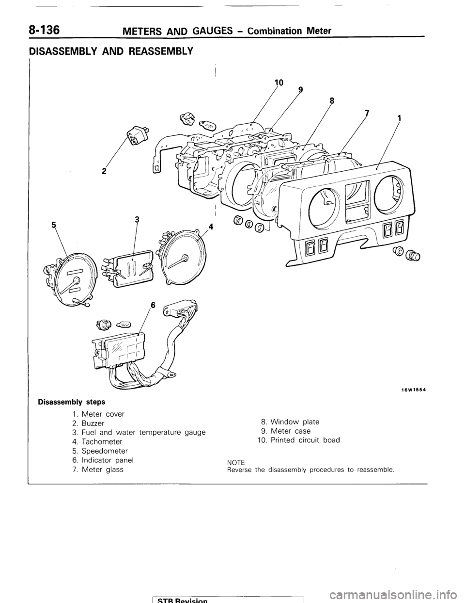
DISASSEMBLY AND REASSEMBLY
I
10
16W1664
I Disassembly steps
1. Meter cover
2. Buzzer
8. Window plate
3. Fuel and water temperature gauge 9. Meter case
4. Tachometer
10. Printed circuit boad
5. Speedometer
6. Indicator panel
NOTE 7. Meter glass Reverse the disassembly procedures to reassemble. 1 STB Revision -1
Page 158 of 284
8-138 METERS AND GAUGES - s-meter Unit
16W678
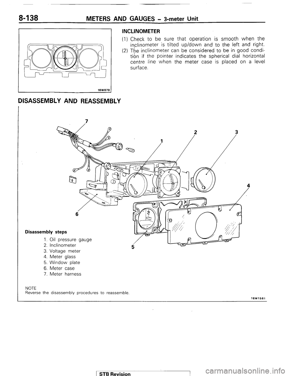
DISASSEMBLY AND REASSEMBLY
INCLINOMETER
(1) Check to be sure that operation is smooth when the
inclinometer is tilted up/down and to the left and right.
(2) The i,nclinometer can be considered to be in good condi-
tion If the pointer indicates the spherical dial horizontal
centre line when the meter case is placed on a level
surface.
6
Disassembly steps
1. Oil pressure gauge
2. Inclinometer
3. Voltage meter
4. Meter glass
5. Window plate
6. Meter case
7. Meter harness
NOTE
Reverse the disassembly procedures to reassemble.
16W1561
1 ST6 Revision
Page 183 of 284
WIPER AND WASHER SYSTEM -Specifications 8-163
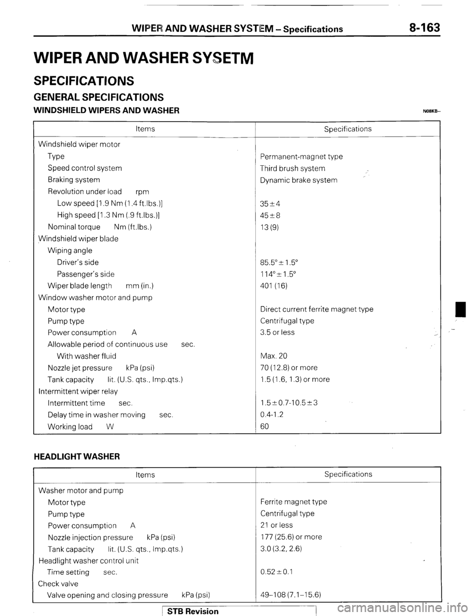
WIPER AND WASHER SYSETM
SPECIFICATIONS
GENERAL SPECIFICATIONS
WINDSHIELD WIPERS AND WASHER NOBKB-
Items
Windshield wiper motor
Type
Speed control system
Braking system
Revolution under load
wm
Low speed [I .9 Nm (1.4 ft.lbs.)]
High speed [I .3 Nm (.9 ftlbs.)]
Nominal torque Nm (ftlbs.)
Windshield wiper blade
Wiping angle
Driver’s side
Passenger’s side
Wiper blade length mm (in.)
Window washer motor and pump
Motor type
Pump type
Power consumption A
Allowable period of continuous use
With washer fluid
Nozzle jet pressure kPa (psi) Sbecifications
sec.
Tank capacity lit. (US. qts., Imp.qts.)
Intermittent wiper relay
Intermittent time sec.
Delay time in washer moving sec.
Working load W
HEADLIGHT WASHER
Items
Washer motor and pump
Motor type
Pump type
Power consumption A
Nozzle injection pressure kPa (psi)
Tank capacity lit. (U.S. qts., Imp.qts.)
Headlight washer control unit
Time setting sec.
Check valve
Valve opening and closing pressure kPa (psi) ‘ermanent-magnet type
Third brush system
Dynamic brake system
3524
45?8
13(g)
35.5” & 1.5”
114”51.5”
401 (16)
Iirect current ferrite magnet type
Zentrifugal type
3.5 or less
Max. 20
70 (12.8) or more
1.5 (1.6, 1.3) or more
1.5~0.7-10.5~3
0.4-I .2
60
Specifications
Ferrite magnet type
Centrifugal type
21 or less
177 (25.6) or more
3.0 (3.2, 2.6)
0.52 -+ 0.1
49-108(7.1-15.6) ,-
1 STB Revision
Page 184 of 284
8-164 WIPER AND WASHER SYSTEM -Specifications
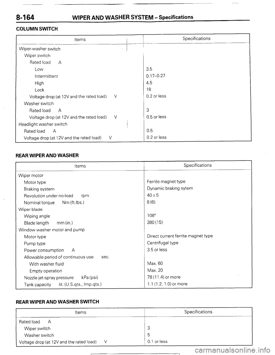
COLUMN SWITCH
L
Specifications
Wiper-washer switch
Wiper switch
Rated load A
Low
intermittent
High
Lock
Voltage drop (at
Washer switch
Rated load A
Voltage drop (at 2V and the rated load) V
2V and the rated load) V
/
Headlight washer switch I
Rated load A
Voltage drop (at 12V and the rated load) V
REAR WIPER AND WASHER
Items
Wiper motor
Motor type
Braking system
Revolution under no-load
m
Nominal torque Nm (ftlbs.)
Wiper blade
Wiping angle
Blade length mm (in.)
Window washer motor and pump
Motor type
Pump type
Power consumption A
Allowable period of continuous use
With washer fluid
Empty operation sec.
Nozzle jet-spray pressure kPa (psi) 78 (11.4) or more
Tank capacity lit. (U.S.qts., Imp.qts.) 1 .I (1.2, 1 .O) or more 3.5
0.17-0.27
4.5
18
0.2 or less
3
0.5 or less
0.5
0.2 or less
Specifications
Ferrite magnet type
Dynamic braking sytem
4025
8 (6)
108
380(15)
Direct current ferrite magnet type
Centrifugal type
3.5 or less
Max. 60
Max. 20
REAR WIPER AND WASHER SWITCH
Items Specifications
Rated load A
Wiper switch 3
Washer switch 5
Voltage drop (at 12V and the rated load) V 0.1 or less
1 STB Revision
Page 195 of 284
WIPER AND WASHER SYSTEM - Rear Wiper 8-175
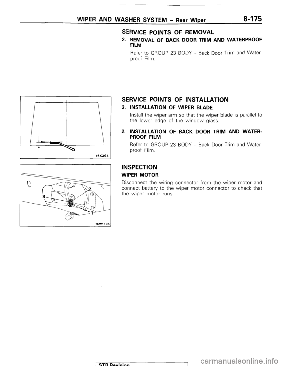
SERVICE POINTS OF REMOVAL
2. REMOVAL OF BACK DOOR TRIM AND WATERPROOF
FILM
Refer to GROUP 23 BODY - Back Door Trim and Water-
proof Film.
I 16K394 1
SERVICE POINTS OF INSTALLATION
3. INSTALLATION OF WIPER BLADE
Install the wiper arm so that the wiper blade is parallel to
the lower edge of the window glass.
2. INSTALLATION OF BACK DOOR TRIM AND WATER-
PROOF FILM
Refer to GROUP 23 BODY - Back Door Trim and Water-
proof Film.
INSPECTION
WIPER MOTOR
Disconnect the wiring connector from the wiper motor and
connect battery to the wiper motor connector to check that
the wiper motor runs.
I STB Revision
Page 223 of 284
BACK DOOR WINDOW DEFOGGER - Specifications / Special Tools
BACK DOOR WINDOW DEFOGGER
8-203
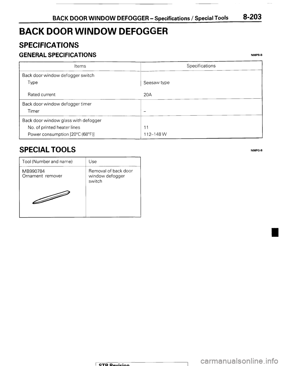
SPECIFICATIONS
( ;ENERAL SPECIFICATIONS NOOPB-B
Items
Back door window defogger switch
Type Seesaw type Specifications
Rated current
Back door window defogger timer
Timer
Back door window glass with defogger
No. of printed heater lines
Power consumption [2O”C (68”F)] 20A
-
11
112-148W
SPECIAL TOOLS
Tool (Number and name)
MB990784
Ornament remover Use
Removal of back door
window defogger
switch
NOBPG-B
1 STB Revision
Page 224 of 284
8-204 I BACK DOOR WINDOW DEFOGGER-Troubleshooting
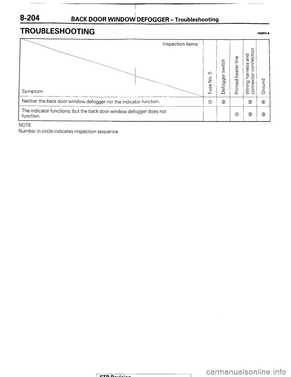
TROUBLESHOOTING NOBPH-B
Neither the back door window defogger nor the indicator function.
0 0 0 @
The indicator functions, but the back door window defogger does not
function.
0 0 0
.---
Number in circle indicates inspection sequence.
/ STB Rqvision
Page 225 of 284
BACK DOOR WINDOW DEFOGGER - Circuit Diagram 8-205
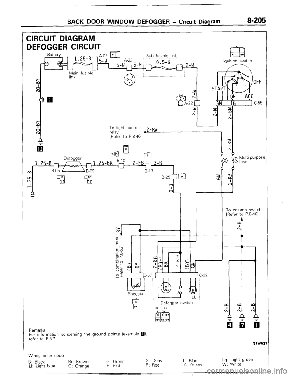
CIRCUIT DUAGRAM
DEFOGGER CIRCUIT -t IDI L
m
- H-UL Ll&J Sub fusible link
5-w A-23 0.5-G 1 5-w"5'w m
z-w ,
u
fusible ignition switch
Main
link
To light control
relay w zmR~
[Refer to P.8-461
q--l-
2 @fuse
i
Multi-purpose m
E
c:
t
To column switch
[Refer to P.8-461
1.25-B
a
c!
Rheostat
Defogger switch a
cl
31 W02:
Remarks
For information concerning the ground points (example:D).
refer to P.8-7.
Wiring color code
B: Black Br: Brown G: Green Gr: Gray L: Blue Lg: Light green
LI: Light blue 0: Orange P: Pink R: Red Y: Yellow W: White STB Revision
Page 226 of 284
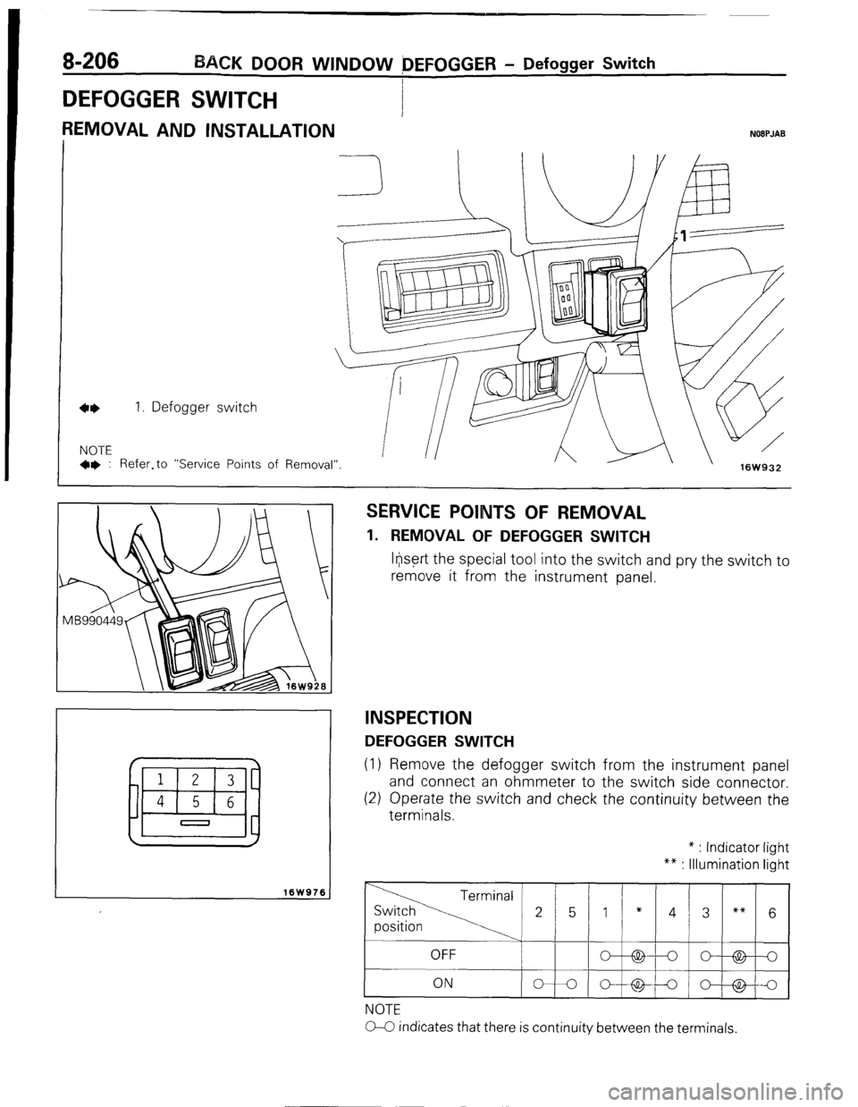
DEFOGGER SWITCH
1
REMOVAL AND INSTALLATION
8-206 BACK DOOR WINDOW OEFOGGER - Defogger Switch
I
NOEPJAB
1. Defogger switch
NOTE
+* : Refer.to “Service Points . ^
I_ A w
ot Kernoval” 16W932
I
16W976 J
SERVICE POINTS OF REMOVAL
1. REMOVAL OF DEFOGGER SWITCH
lr@rt the special tool into the switch and pry the switch to
remove it from the instrument panel.
INSPECTION
DEFOGGER SWITCH
(1) Remove the defogger switch from the instrument panel
and connect an ohmmeter to the switch side connector.
(2) Operate the switch and check the continuity between the
terminals. * : Indicator light
** : Illumination light
NOTE
0-C indicates that there is continuity between the terminals.
1 STB Revision
~-E
Page 227 of 284
BACK DOOR WINDOW DEFOGGER - Printed Heater Lines B-207
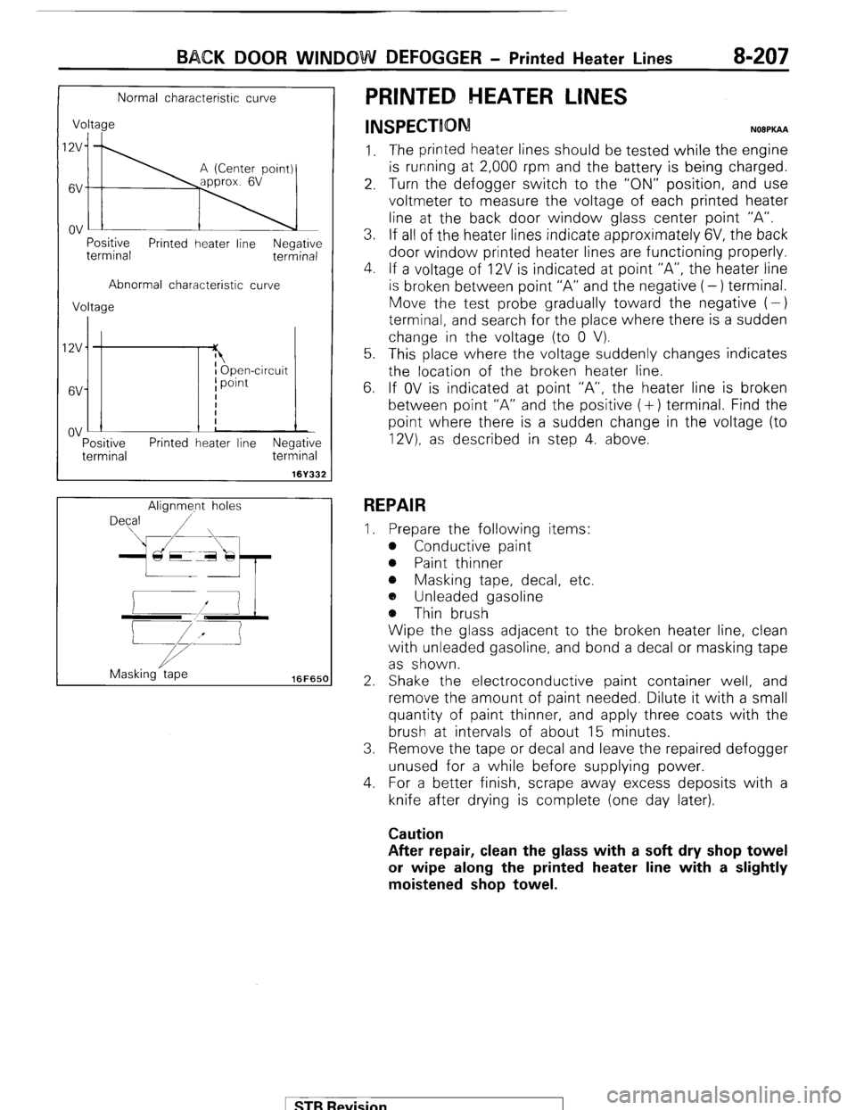
Normal characteristic curve
Voltage
I;\
Positive
terminal Printed heater line Negative
terminal
Abnormal characteristic curve
Voltage
IZV
6V
ov :-
Tf I Open-circuit
I point
I
i
!
Positive Printed heater line Negative
terminal terminal
161332
Alignme.nt holes
Masking tape
16FfiSCl
PRINTED HEATER LINES
INSPECTION N08PKAA
1. The printed heater lines should be tested while the engine
is running at 2,000 rpm and the battery is being charged.
2. Turn the defogger switch to the “ON” position, and use
voltmeter to measure the voltage of each printed heater
line at the back door window glass center point “A”.
3. If all of the heater lines indicate approximately 6V, the back
door window printed heater lines are functioning properly.
4. If a voltage of 12V is indicated at point “A”, the heater line
is broken between point “A” and the negative (-) terminal.
Move the test probe gradually toward the negative (-)
terminal, and search for the place where there is a sudden
change in the voltage (to 0 V).
5. This place where the voltage suddenly changes indicates
the location of the broken heater line.
6. If OV is indicated at point “A”, the heater line is broken
between point “A” and the positive (+) terminal. Find the
point where there is a sudden change in the voltage (to
12V). as described in step 4. above.
REPAIR
I. Prepare the following items:
e Conductive paint
@ Paint thinner
e Masking tape, decal, etc.
a, Unleaded gasoline
@ Thin brush
Wipe the glass adjacent to the broken heater line, clean
with unleaded gasoline, and bond a decal or masking tape
as shown.
2. Shake the electroconductive paint container well, and
remove the amount of paint needed. Dilute it with a small
quantity of paint thinner, and apply three coats with the
brush at intervals of about 15 minutes.
3. Remove the tape or decal and leave the repaired defogger
unused for a while before supplying power.
4. For a better finish, scrape away excess deposits with a
knife after drying is complete (one day later).
Caution
After repair, clean the glass with a soft dry shop towel
or wipe along the printed heater line with a slightly
moistened shop towel.
1 STB Revision