Circuit diagram MITSUBISHI MONTERO 1987 1.G Owner's Manual
[x] Cancel search | Manufacturer: MITSUBISHI, Model Year: 1987, Model line: MONTERO, Model: MITSUBISHI MONTERO 1987 1.GPages: 284, PDF Size: 14.74 MB
Page 173 of 284
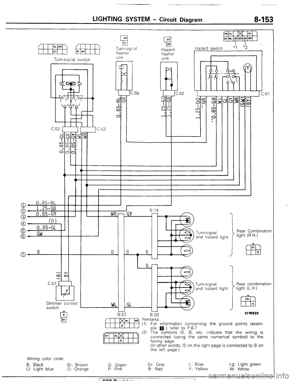
LIGHTING SYSTEM - Circuit Diagram 8-153
Turn-signal
flasher Hazard
flasher I iazard switch “1
unit unit
I r Turn-srgnal switch
I
l!d C-62
a
I
::
C
-W‘\*1W++ n
c
I
::
C
n
*
‘\&VB/
I v-l--c 0.85-RL
o- 1 ')r r-
Rear Combination
light (R.H.) Turn -signal
and hazard light B
Y-
a- B B
Dimmer control
switch Rear combination
light (L.H.) OL
EZB B
WL
37W029 B-20
-
m Rern~:~s~ ) refer to P 8-7. (1) For information concerning the ground points (exam-
(2) The symbols 0. 0, etc. indicate that the wiring is
connected (using the same numerical symbol) to the
(In other words, 0 on the right page is connected to 0 on
the left page.)
Wiring color code
B: Black Br: Brown
G: Green Gr: Gray L: Blue Lg: Light green
LI: Light blue
0: Orange P: Pink
R: Red Y: Yellow
W: White ) STB Revision
Page 174 of 284
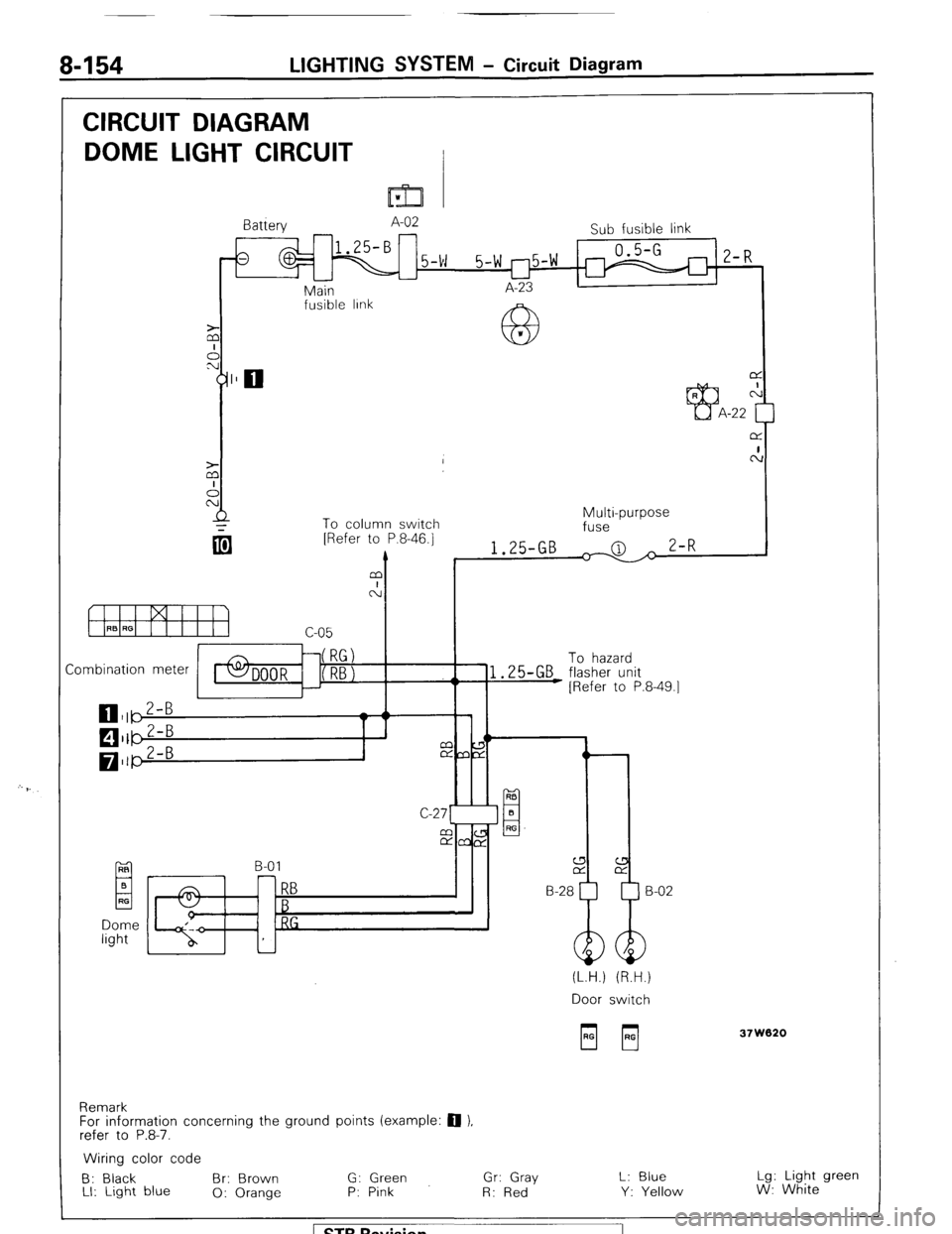
8-154 LIGHTING SYSTEM - Circuit Diagram
CIRCUIT DIAGRAM
DOME LIGHT CIRCUIT
I=32 v
Battery A-02
Sub fusible link
1
0.5-G
5-w 5-w r-l5-w 1 2-R
u
Main I A-23 I
I
fusible IInk
63 *
L
To column switch
Combination meter To hazard
EL B-01 RB
El B
RF
RB H-28
B
RG
(L.H.) (R.H.)
Door switch
Remark
For information concerning the ground points (example: 0 ),
refer to P.8-7. 37W020
Wiring color code
B: Black Br: Brown G: Green Gr: Gray L: Blue Lg: Light green
LI: Light blue
0: Orange P: Pink
R: Red Y: Yellow W: White
1 STB Revision
Page 175 of 284
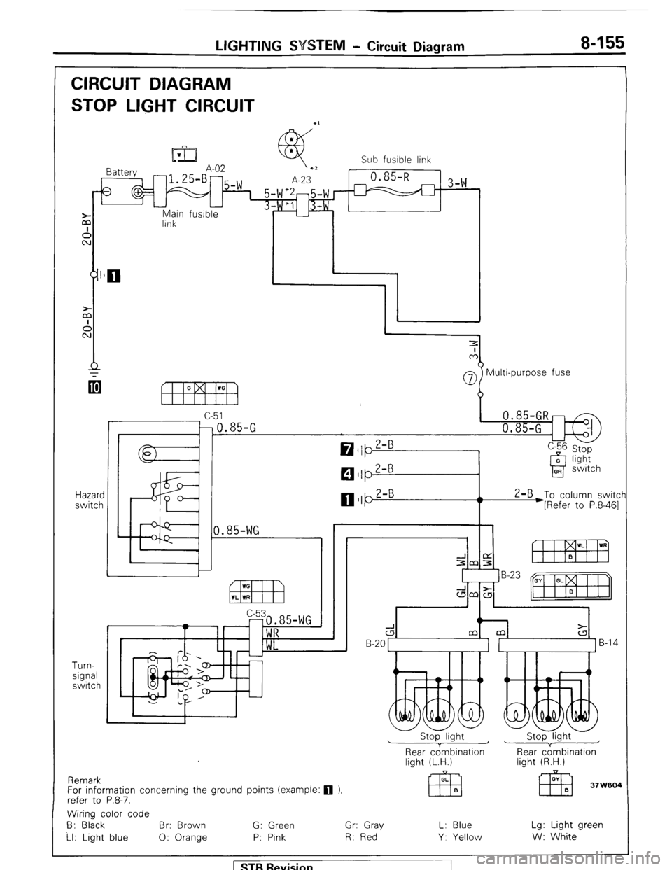
LIGHTING SYSTEM - Circuit Diagram 8-155
CIRCUIT DIAGRAM
STOP LIGHT CIRCUIT
Main fusible
link
Hazard
switch
Turn-
signal
switch Sub fusible link
-1 3-w
07 Multr-purpose fuse
c-51
-0.85-G
0.85-WG 2-B
To column switcf
*[Refer to P.8-461
Remark
For information concerning the ground points (example:
q ).
refer to P.8-7.
d B-20 1 ]B-14
Stop light ~
1 Stop light
Rear cdmbination
light (L.H.) Rear c;mbination
light (R.H.)
Wiring color code
B: Black Br: Brown G: Green Gr: Gray L: Blue Lg: Light green
Ll: Light blue 0: Orange P: Pink R: Red Y. Yellow W: White
1 STB Revision
Page 176 of 284
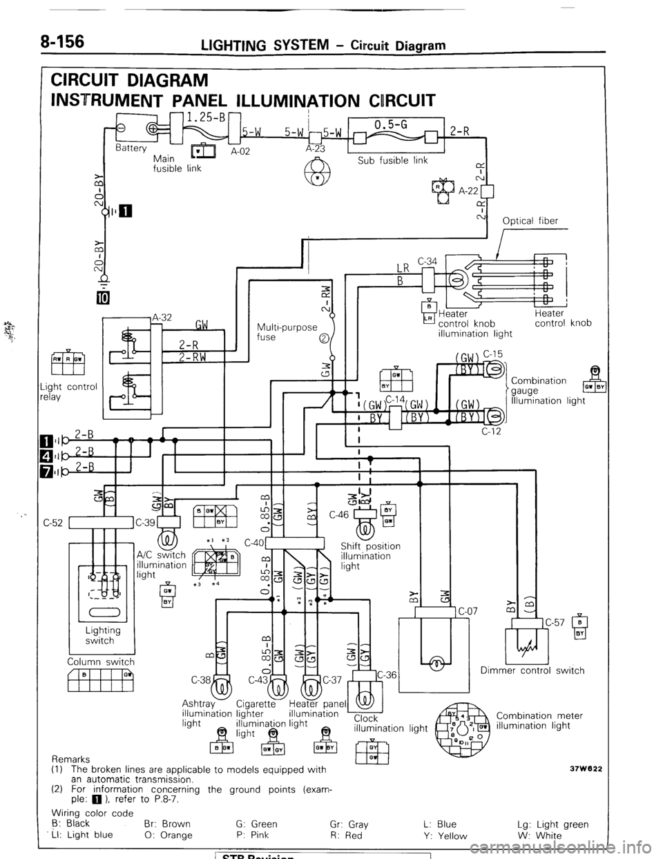
8-156 LIGHTING SYSTEM - Circuit Diagram
CIRCUIT DIAGRAM
INSTRUMENT PANEL ILLUMINATION CORCUIT
-1.25-B-
0
.5-w 0.5-G
2-R
Battery
-Err
5-w 15-w r
Main ’ A-02 A-23
Sub fusible link
fusible link a
I
z N
A A-22 [
cy]llo CY
c-i
Optical fiber
I
Multi-purpose
fuse Heater
control knob
illumination light Heater
control knob
ght control
lay Combination
gauge B 01 0’
Illumination light
/ n
c
C
-
c-57 0 ti
Q BY Lighting
switch
Dimmer control switch
rel
Combination meter
illumination light illumination lighter
Remarks
(1) The broken lines are applicable to models eouipped with
37W822 an automatic transmission.
(2) For information concerning the ground points (exam-
ple: 0 1, refer to P.8-7.
Wiring color code
6: Black
Br: Brown G: Green
Ll: Light blue Gr: Gray
0: Orange P: Pink
R: Red L: Blue
Y: Yellow Lg: Light green
W: White 1 ST6 Revision
Page 188 of 284
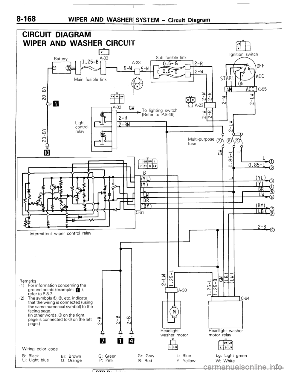
8468 WIPER AND WASHERS SYSTEM - Circuit Diagram
CIRCUIT DIAGRAM
WIPER AND WASHER CIRCU
Ignition switch
lattery
-1.SBAz2 Sub fusible link
A-23
0.5-G
1 5-w m5-w
U
2-R
Z-W
Main fusible link A IL
J.
c
7
C
-
-
-
-
-
-
J A
:
II,
L
.
> 0.85-L '
Light
control
relay P I? 1 -RW ,
Multi-purpose @
fuse
2-B 9
I--
Intermittent wiper control relay
-r ,m:
JJ-
-.
1 C-64
Headlight washer
motor relay Remarks
(I) For information concernina the
ground points (example: a ),
refer to P.8-7.
(2) The svmbols 0.0. etc. indicate
that the wiring is connected (using
the same numerical symbol) to the
facing page.
(In other words, 0 on the right
page is connected to 0 on the left
page.)
a
c: m LB
EEEI L B L1 Wiring color code
B: Black
Br: Brown
LI: Light blue 0: Orange G: Green
P: Pink Gr: Gray
R: Red L: Blue
Y: Yellow Lg: Light green
W: White
/ STB Revision
Page 189 of 284

WIPER AND WASHER SYSTEM - Circuit Diagram 8469
m Column switch -- Front-koer switch -1
Rear wiper and
washer switch
r I Headlight
washer
switch
o-(YL)
@JYJ
(+ BR
@- Lw
L B-l 2
w2-B
! )
1
L
(
7 A-14
1 B-07
81
M
A-58
>
1
GE&washer I
Rear wiper Front washer
motor Front wiper
motor motor
motor
37W124
/ STB Revision
Page 205 of 284
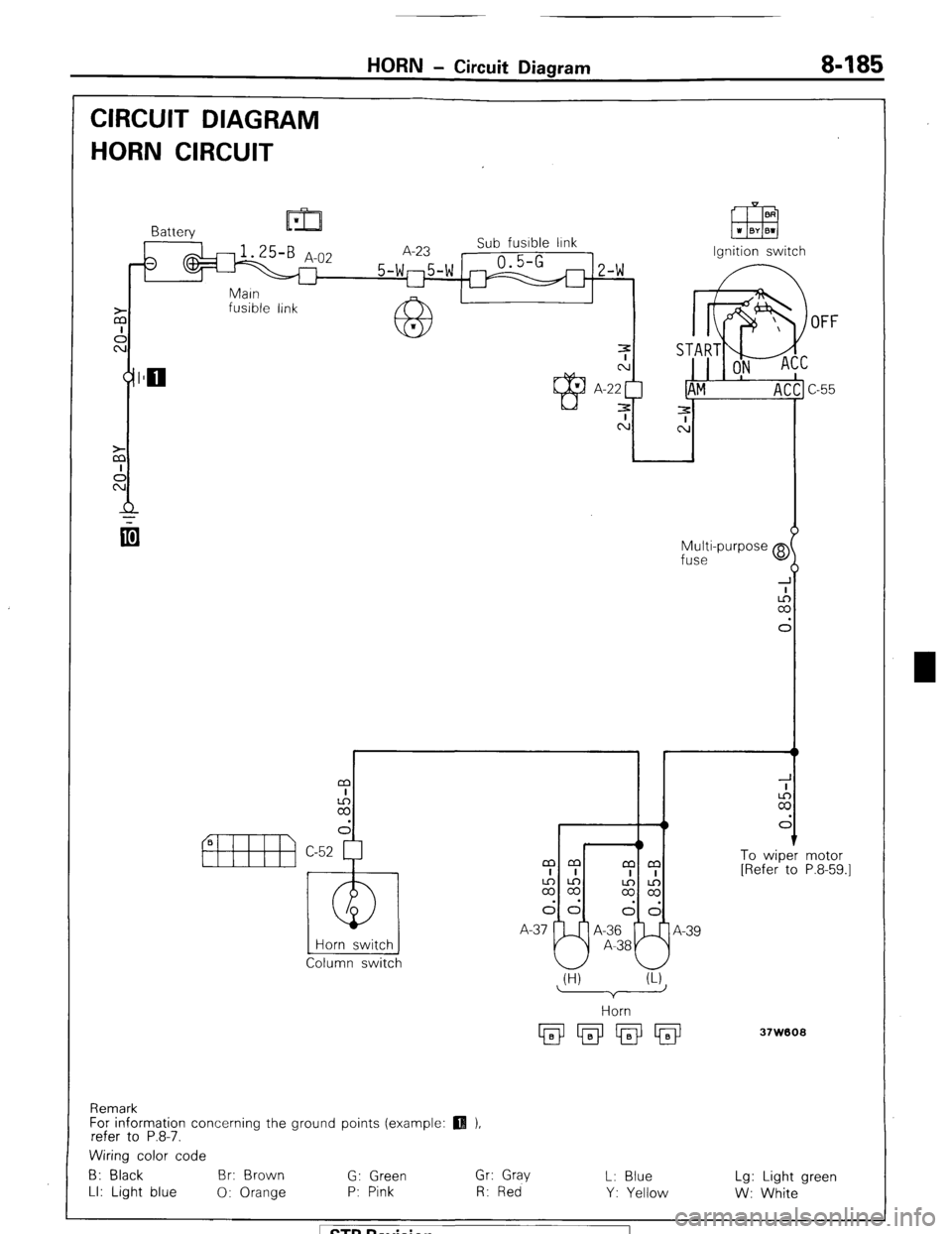
HORN - Circuit Diagram 8485
CIRCUIT DIAGRAM
HORN CIRCUIT
fusible link
OFF
Multi-purpose @
fuse
I r t
m
I
2
d
1 To wiper
[Refer to
Horn switch
Column switch mm
mm
I I
I I
2%
$2
dd
I--J!
dd
A-37 A-36
A-39
A-38 motor
P.8-59.1
(H) (U
37W608
Remark
For information concerning the ground points (example:
refer to P.8-7.
Wiring color code
B: Black Br: Brown
G: Green Gr: Gray
L: Blue Lg: Light green
LI: Light blue
0: Orange P: Pink R: Red
Y: Yellow
W: White 1 STB Revision
Page 209 of 284
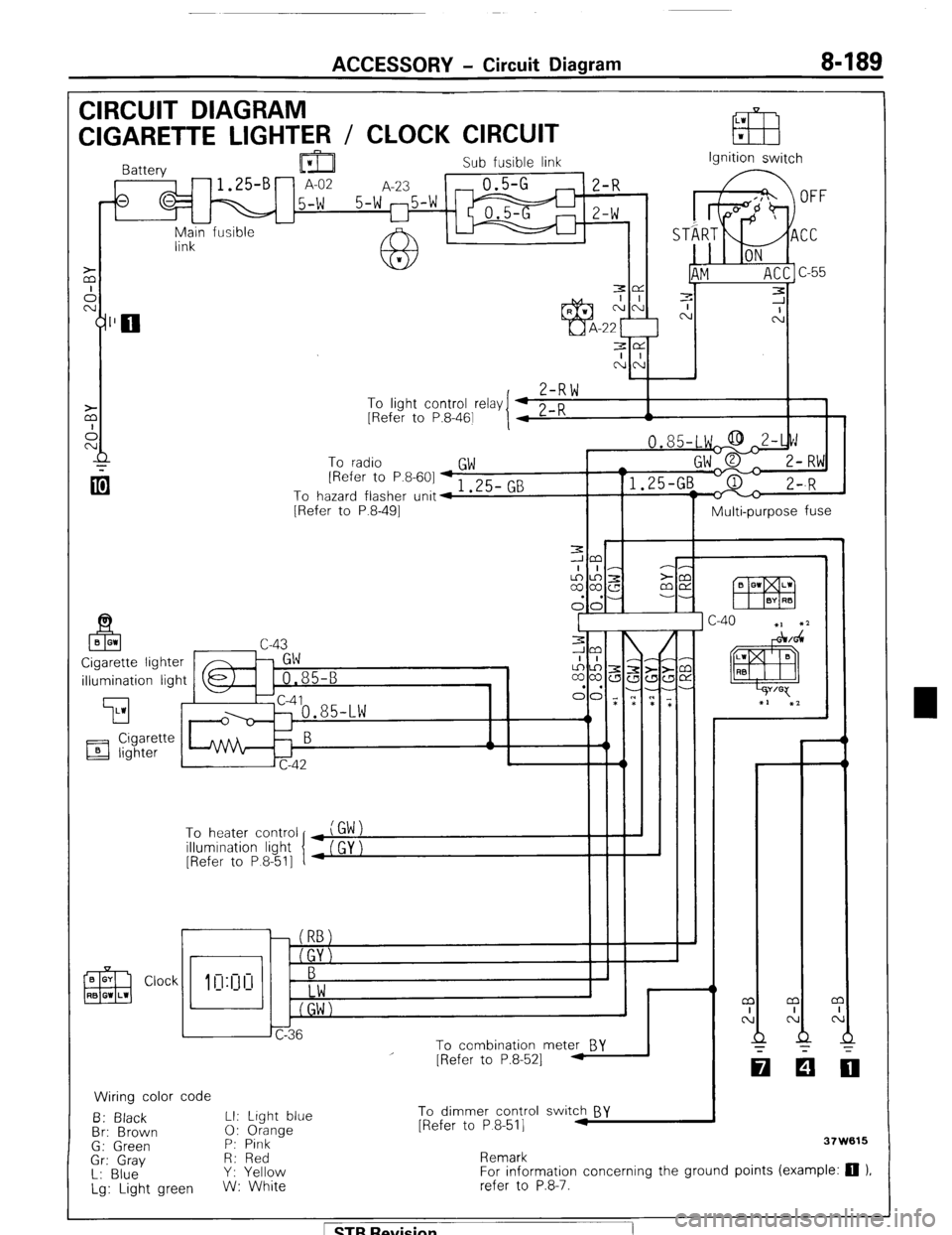
ACCESSORY - Circuit Diagram 8-189
CIRCUIT DIAGRAM
LW
CIGARETTE LIGHTER / CLOCK CIRCUIT EB w
Sub fusible link
,-fs q M 15-W 5-W 25-W m ;I;
I I
-
Main fusible -
link Ignition switch
3e
I I
NN
,
Z-RW To
linht cnntrnl r&v I 4 0 n
I 1 - .J . __._ - -., [Refer to P.8-461
I 4 L-K A
To radio
GW [Refer to P.8-601 + 1 .25- GB
To hazard flasher unit4
[Refer to P.8-491
Multi-purpose fuse
illumination light
’ To heater control
illumination light
[Refer to P 8-511
r
i I
To combination meter BY
Wiring color code
B: Black LI: Light blue
Br: Brown 0: Orange
G: Green P: Pink
Gr: Gray R: Red
L: Blue Y: Yellow
Lg: Light green W: White
I
I - - m
I
N
Q
-
[Refer to P.8-521 -
To dimmer control switch BY
[Refer to P 8-511 .I
Remark 37W615
For information concerning the ground points (example: 0 ).
refer to P.8-7.
1 STB Revision
Page 214 of 284
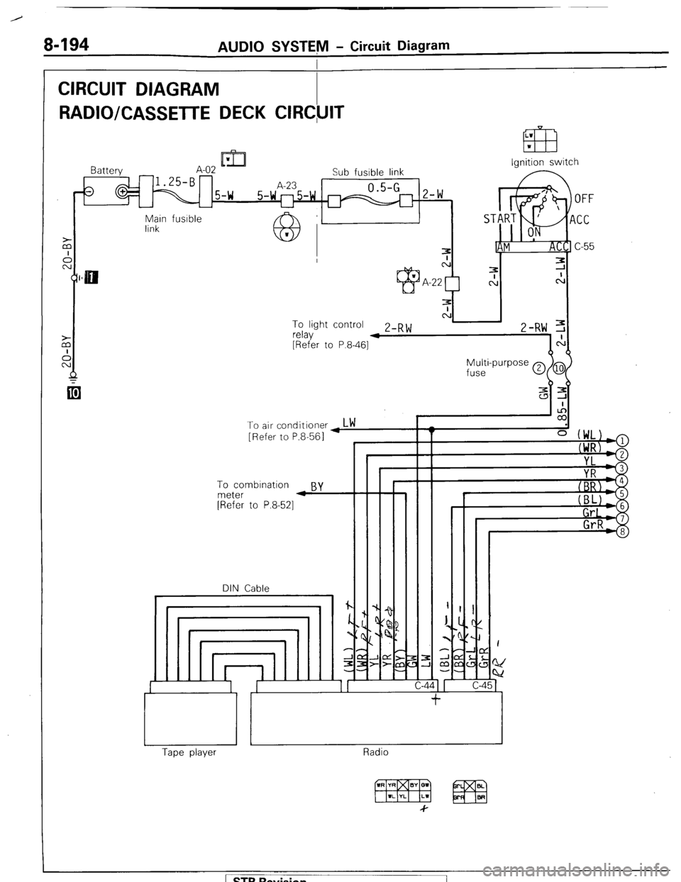
8-194 AUDIO SYSTEM - Circuit Diagram
CIRCUIT DIAGRAM
I
RADIO/CASSETTE DECK CIRC,UIT
LW
033 w
Ignition switch
Battery A-02 IL-
Sub fusible link
0 1.25-B A-23 0.5-G 2 w
1 5-w 5-w ll5-w m -
u
Main fusible
link
N To light control
relav Z-RW 3 4
[Refer to P.8-461
Z-RW,,:
To air conditioner,LW
[Refer to P.8-561
To combination
By meter 4
[Refer to P.8-521
DIN Cable
I
/
J
I Y
=z
I
c- 45 -
It, /II
1 L
Radio Tape player
[ STB Revision
Page 215 of 284
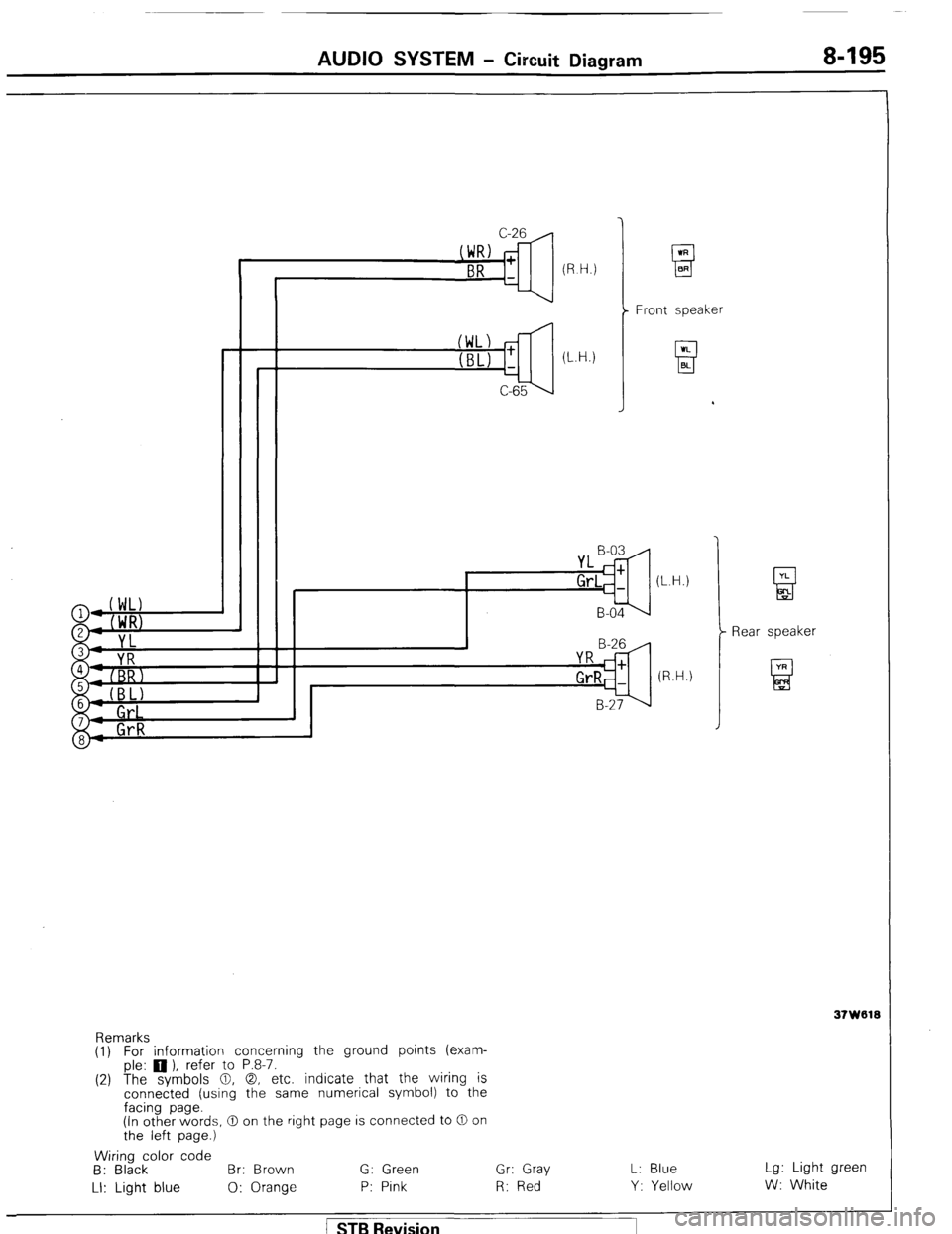
AUDIO SYSTEM - Circuit Diagram 8-195
(L.H.)
C-65 Front speaker
YL B-03
Gr,=: (L.H.)
B-04
B-29
YR c
GrRC+
(R.H.)
B-2?’
Remarks
(1) For information concerning the ground points (exam-
ple: 0 ), refer to P.8-7.
(2) The symbols 0, 0, etc. indicate that the wiring is
connected (using the same numerical symbol) to the
facing page.
(in other words, 0 on the right page is connected to 0 on
the left page.)
Wiring color code
B: Black Br: Brown G: Green Gr: Gray L: Blue
LI: Light blue 0: Orange P: Pink R: Red Y: Yellow Rear speaker
Lg: Light green
W: White
/ STB Revision