alternator MITSUBISHI MONTERO 1987 1.G Owner's Manual
[x] Cancel search | Manufacturer: MITSUBISHI, Model Year: 1987, Model line: MONTERO, Model: MITSUBISHI MONTERO 1987 1.GPages: 284, PDF Size: 14.74 MB
Page 106 of 284
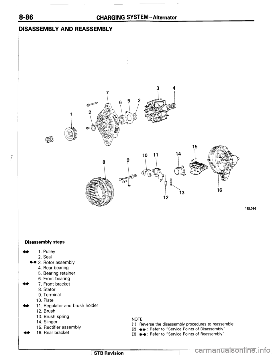
CHARGING SYSTEM-Alternator
10 11 14
8 ? \I I
Disassembly steps
4* 1. Pulley
2. Seal
l a 3. Rotor assembly
4. Rear bearing
5. Bearing retainer
6. Front bearing
4*
7. Front bracket
8. Stator
9. Terminal
10. Plate
4* 11. Regulator and brush holder
12. Brush
13. Brush spring
14. Slinger
15. Rectifier assembly
4, 16. Rear bracket NOTE
(1) Reverse the disassembly procedures to reassemble.
(2) +e : Refer to “Service Points of Disassembly”.
(3) l
+ : Refer to “Service Points of Reassembly”.
1 EL666 1 STB Revision
Page 107 of 284
CHARGING SYSTEM-Alternator 8-87
6ELllt
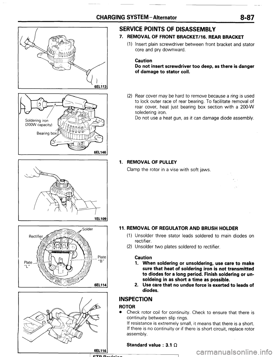
SERVICE POINTS OF DISASSEMBLY
7. REMOVAL OF FRONT BRACKET/lG. REAR BRACKET
(1) Insert plain screwdriver between front bracket and stator
core and pry downward.
Caution
Do not insert screwdriver too deep, as there is danger
of damage to stator coil.
(2) Rear cover may be hard to remove because a ring is used
to lock outer race of rear bearing. To facilitate removal of
rear cover, heat just bearing box section with a 200-W
soledering iron.
Do not use a heat gun, as it can damage diode assembly.
1. REMOVAL OF PULLEY
Clamp the rotor in a vise with soft jaws.
11. REMOVAL OF REGULATOR AND BRUSH HOLDER
(1) Unsolder three stator leads soldered to main diodes on
rectifier.
(2) Unsolder two plates soldered to rectifier.
Caution
1. When soldering or unsoldering, use care to make
sure that heat of soldering iron is not transmitted
to diodes for a long period. Finish soldering or un-
soldeing in as short a time as possible.
2. Use care that no undue force is exerted to leads of
diodes.
INSPECTION
ROTOR
l Check rotor coil for continuity. Check to ensure that there is
continuity between slip rings.
If resistance is extremely small, it means that there is a short.
If there is no continuity or if there is short circuit, replace rotor
assembly.
Standard value : 3.1 f2
. . .
I 1 STB hewsion
Page 108 of 284
8-88 CHARGING SYSTEM-Alternator
6EL115
3ELOlO
lELll0
lELll1
A
) STBRc
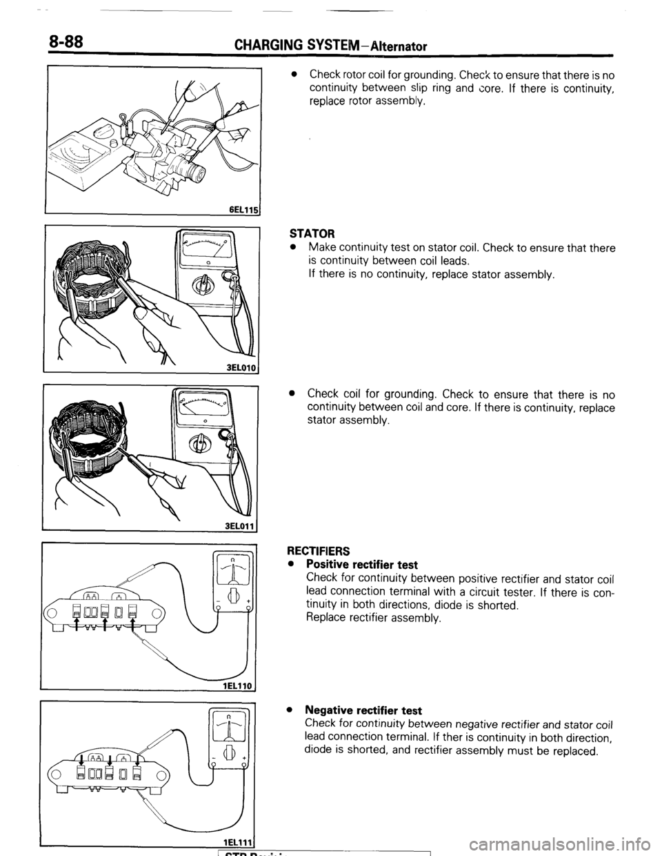
l Check rotor coil for grounding. Check to ensure that there is no
continuity between slip ring and core. If there is continuity,
replace rotor assembly.
STATOR
l Make continuity test on stator coil. Check to ensure that there
is continuity between coil leads.
If there is no continuity, replace stator assembly.
l Check coil for grounding. Check to ensure that there is no
continuity between coil and core. If there is continuity, replace
stator assembly.
RECTIFIERS
l Positive rectifier test
Check for continuity between positive rectifier and stator coil
lead connection terminal with a circuit tester. If there is con-
tinuity in both directions, diode is shorted.
Replace rectifier assembly.
l Negative rectifier test
Check for continuity between negative rectifier and stator coil
lead connection terminal. If ther is continuity in both direction,
diode is shorted, and rectifier assembly must be replaced.
evision
-7
Page 110 of 284
8-90 CHARGING SYSTEM-Alternator
Rear bracket Wire
6EL122
6EL123 I
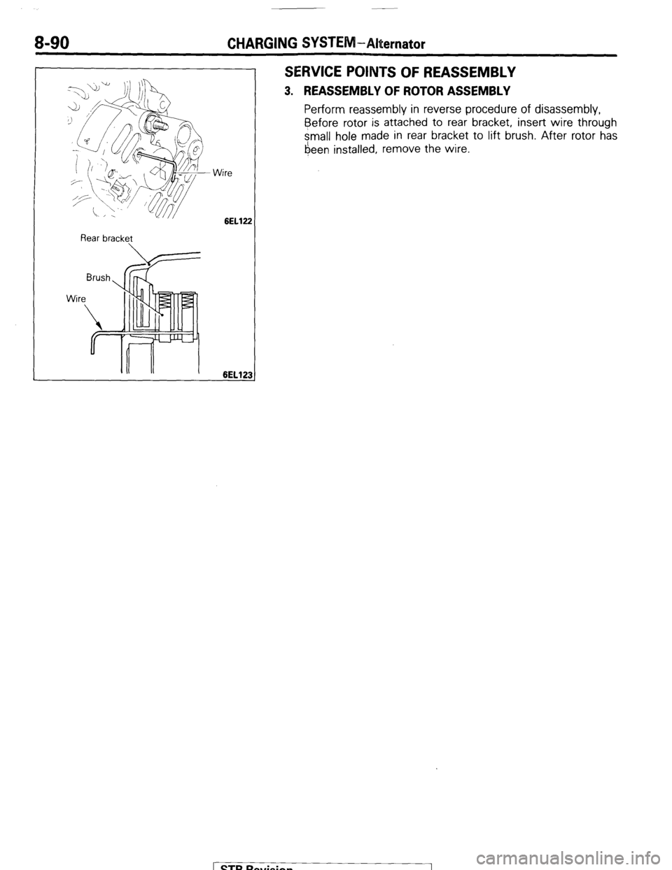
SERVICE POINTS OF REASSEMBLY
3. REASSEMBLY OF ROTOR ASSEMBLY
Perform reassembly in reverse procedure of disassembly,
Before
rotor is attached to rear bracket, insert wire through
small hole made in rear bracket to lift brush. After rotor has
6een installed, remove the wire.
STB Revision
Page 148 of 284
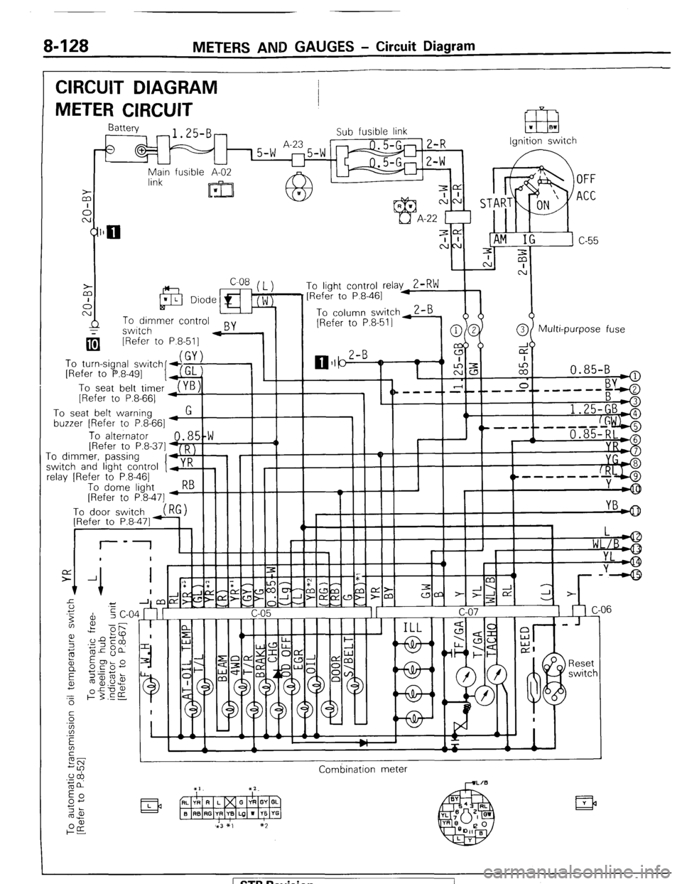
8-128 METERS AND GAUGES - Circuit Diagram
CIRCUIT DIAGRAM
METER CIRCUIT
Ignition switch
q [Refer to
To turn-signal switch
[Refer to P.8-491
I
To seat belt timer
[Refer to P.8-661 P.8-511 -
To seat belt warning
buzzer [Refer to P.8-661
1.25-GBA
, ^.
To alternator 48,5!W III -1 / 1 , 1 '----f--d+ii$$j IRefer to P.8.371 D I
.I_ -0 dimmkr, passinq
‘I+,:’ ! I I I II -I
I r I I I II YI
;witch and light control y K
clay [Refer to P.8-461
To dome liaht 5--hIIII I
----m-w-
[Refer to P&47] -w
Combination meter
( STB Revision
Page 213 of 284
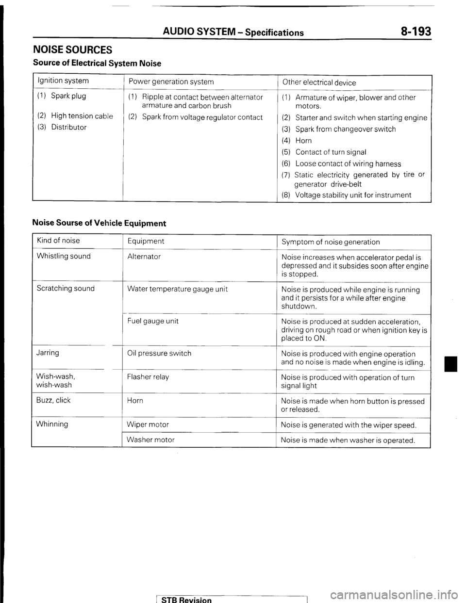
AUDIO SYSTEM - Specifications 8-193
NOISE SOURCES
Source of Electrical System Noise
Ignition system
(1) Spark plug
(2) High tension cable
(3) Distributor Power generation system
(1) Ripple at contact between alternator
armature and carbon brush
(2) Spark from voltage regulator contact
!
Other electrical device
(1) Armature of wiper, blower and other
motors.
(2) Starter and switch when starting engine
(3) Spark from changeover switch
(4) Horn
(5) Contact of turn signal
(6) Loose contact of wiring harness
(7) Static electricity generated by tire or
generator drive-belt
(8) Voltage stability unit for instrument
Noise Sourse of Vehicle Equipment
Kind of noise
Whistling sound Equipment
Alternator Symptom of noise generation
Noise increases when accelerator pedal is
depressed and it subsides soon after engine
is stopped.
Scratching sound
Water temperature gauge unit Noise is produced while engine is running
and it persists for a while after engine
shutdown.
Fuel gauge unit Noise is produced at sudden acceleration,
driving on rough road or when ignition key is
placed to ON.
Jarring
Wish-wash,
wish-wash
Buzz, click Oil pressure switch
Flasher relay
Horn
Wiper motor
Washer motor Noise is produced with engine operation
and no noise is made when engine is idling.
Noise is produced with operation of turn
signal light
Noise is made when horn button is pressed
or released.
Whinning Noise is generated with the wiper speed.
Noise is made when washer is operated.
STB Revision
Page 220 of 284
8-200 AUDIO SYSTEM - Antenna/Noise Suppression
3. REMOVAL OF FRONT FENDER PANEL
Refer to GROUP 23 Body-Front Fender
SEFiVlCE ff OINTS OF INSTALLATION
3. IbSTALLATION OF FRONT FENDER PANEL
Refer to GROUP 23 Body-Front Fender.
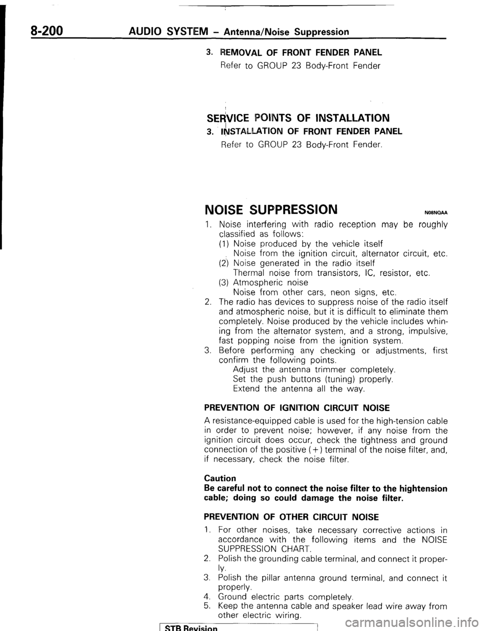
NOISE SWPRESSION N08NOAA
I. Noise interfering with radio reception may be roughly
classified as follows:
(1) Noise produced by the vehicle itself
Noise from the ignition circuit, alternator circuit, etc
(2) Noise generated in the radio itself
Thermal noise from transistors, IC, resistor, etc.
(3) Atmospheric noise
Noise from other cars, neon signs, etc.
2. The radio has devices to suppress noise of the radio itsel f
3. and atmospheric noise, but it is difficult to eliminate them
completely. Noise produced by the vehicle includes whin-
ing from the alternator system, and a strong, impulsive,
fast popping noise from the ignition system.
Before performing any checking or adjustments, first
confirm the following points.
Adjust the antenna trimmer completely.
Set the push buttons (tuning) properly.
Extend the antenna all the way.
PREVENTION OF IGNITION CIRCUIT NOISE
A resistance-equipped cable is used for the high-tension cable
in order to prevent noise; however, if any noise from the
ignition circuit does occur, check the tightness and ground
connection of the positive (+) terminal of the noise filter, and,
if necessary, check the noise filter.
Caution
Be careful not to connect the noise filter to the hightension
cable; doing so could damage the noise filter.
PREVENTION OF OTHER CIRCUIT NOISE
1. For other noises, take necessary corrective actions in
accordance with the following items and the NOISE
SUPPRESSION CHART.
2. Polish the grounding cable terminal, and connect it proper-
ly.
3. Polish the pillar antenna ground terminal, and connect it
properly.
4. Ground electric parts completely.
5. Keep the antenna cable and speaker lead wire away from
other electric wiring.
STB Revision
Page 277 of 284
AIR-CONDITIONING -Service Adjustment Procedures 24-41
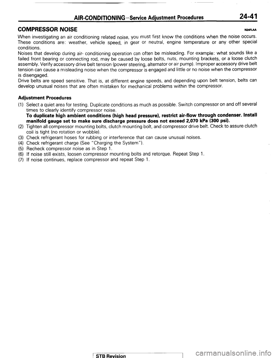
COMPRESSOR NOISE NWLM
When investigating an air conditioning related noise, you must first know the conditions when the noise occurs.
These conditions are: weather, vehicle speed, in gear or neutral, engine temperature or any other special
conditions.
Noises that develop during air- conditioning operation can often be misleading. For example: what sounds like a
failed front bearing or connecting rod, may be caused by loose bolts, nuts, mounting brackets, or a loose clutch
assembly. Verify accessory drive belt tension (power
steering, alternator or air pump). Improper accessory drive belt
tension can cause a misleading noise when the compressor is engaged and little or no noise when the compressor
is disengaged.
Drive belts are speed sensitive. That is, at different engine speeds, and depending upon belt tension, belts can
develop unusual noises that are often mistaken for mechanical problems within the compressor.
Adjustment Procedures
(1) Select a quiet area for testing. Duplicate conditions as much as possible. Switch compressor on and off several
times to clearly identify compressor noise.
To duplicate high ambient conditions (high head pressure), restrict air-flow through
condenser. Install
manifold gauge set to make sure discharge pressure does not exceed 2,070 kPa (300 psi).
(2) Tighten all compressor mounting bolts, clutch mounting bolt, and compressor drive belt. Check to assure clutch
coil is tight (no rotation or wobble).
(3) Check refrigerant hoses for rubbing or interference that can cause unusual noises.
(4) Check refrigerant charge (See “Charging the System”).
(5) Recheck compressor noise as in Step 1.
(6) If noise still exists, loosen compressor mounting bolts and retorque. Repeat Step 1.
(7) If noise continues, replace compressor and repeat Step 1.
1 STB Revision