alternator MITSUBISHI MONTERO 1987 1.G User Guide
[x] Cancel search | Manufacturer: MITSUBISHI, Model Year: 1987, Model line: MONTERO, Model: MITSUBISHI MONTERO 1987 1.GPages: 284, PDF Size: 14.74 MB
Page 94 of 284
8-74 CHARGING SYSTEM -Specifications
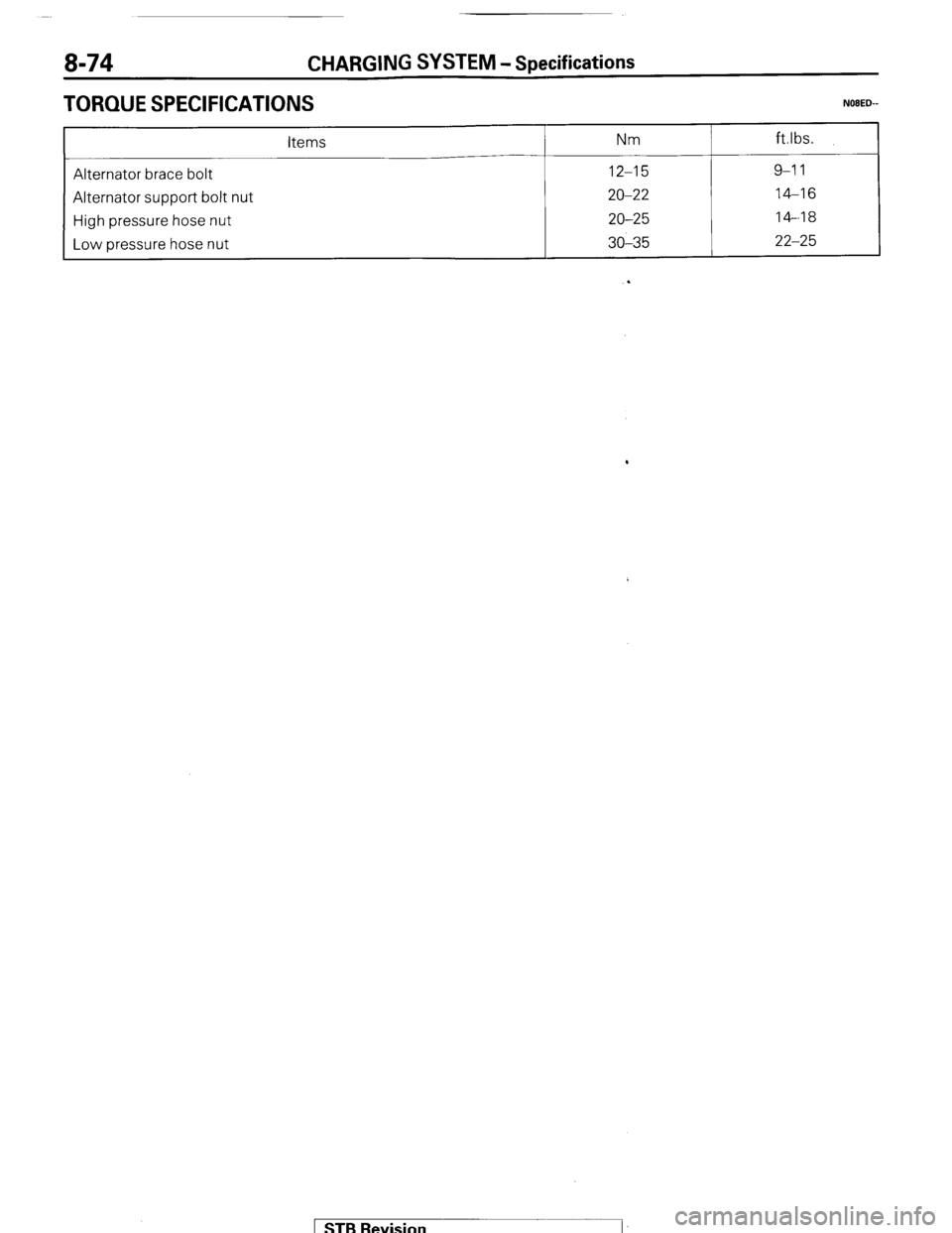
TORQUE SPECIFICATIONS
items Nm ft.lbs.
__-
Alternator brace bolt
12-15
9-l 1
Alternator support bolt nut
20-22
14-16
High pressure hose nut
20-25
14-18
Low hose nut
pressure 30-35
22-25
.
1 STB Revision
Page 95 of 284
CHARGING SYSTEM -Troubleshooting 8-75
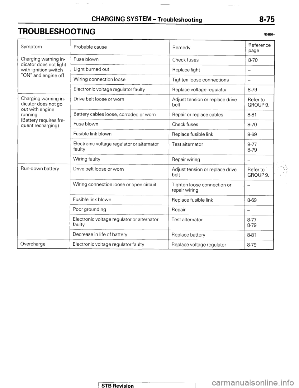
TROUBLESHOOTING
NOBEH-
Symptom Probable cause
Remedy Reference
we
Charging warning in- Fuse blown
dicator does not light
with ignition switch Light burned out
“ON” and engine off. 1
1 Wiring connection loose Check fuses
Replace light
Tighten loose connections 8-70
-
-
Charging warning in-
dicator does not go
out with engine
running
(Battery requires fre-
quent recharging)
L
t
Run-down battery
c
Electronic voltage regulator faulty
Drive belt loose or worn
Battery cables loose, corroded or worn
Fuse blown
Fusible link blown
Electronic voltage regulator or alternator
faulty
Wiring faulty
Drive belt loose or worn
Wiring connection loose or open circuit
Fusible link blown Replace voltage regulator
Adjust tension or replace drive
belt
Repair or replace cables
Check fuses
Replace fusible link
Test alternator
Repair wiring
Adjust tension or replace drive
belt
Tighten loose connection or
repair wiring
Replace fusible link 8-79
Refer to
GROUPS.
8-8 1
8-70
8-69
8-77
8-79
-
Refer to
GROUP 9.
-
8-69
Poor grounding 1 Repair
I-
I I I Electronic voltage regulator or alternator
faulty Test alternator 8-77
8-79
Overcharge Decrease in life of battery
Replace battery
8-81 I
Electronic voltage regulator faulty Replace voltage regulator 8-79
STB Revision
Page 97 of 284
CHARGING SYSTEM - Service Adjustment Procedures 8-77
SERVICE ADJUSTMENT PROCEDUREswmAB
lEL15I
INSPECTION OF THE CHARGING SYSTEM
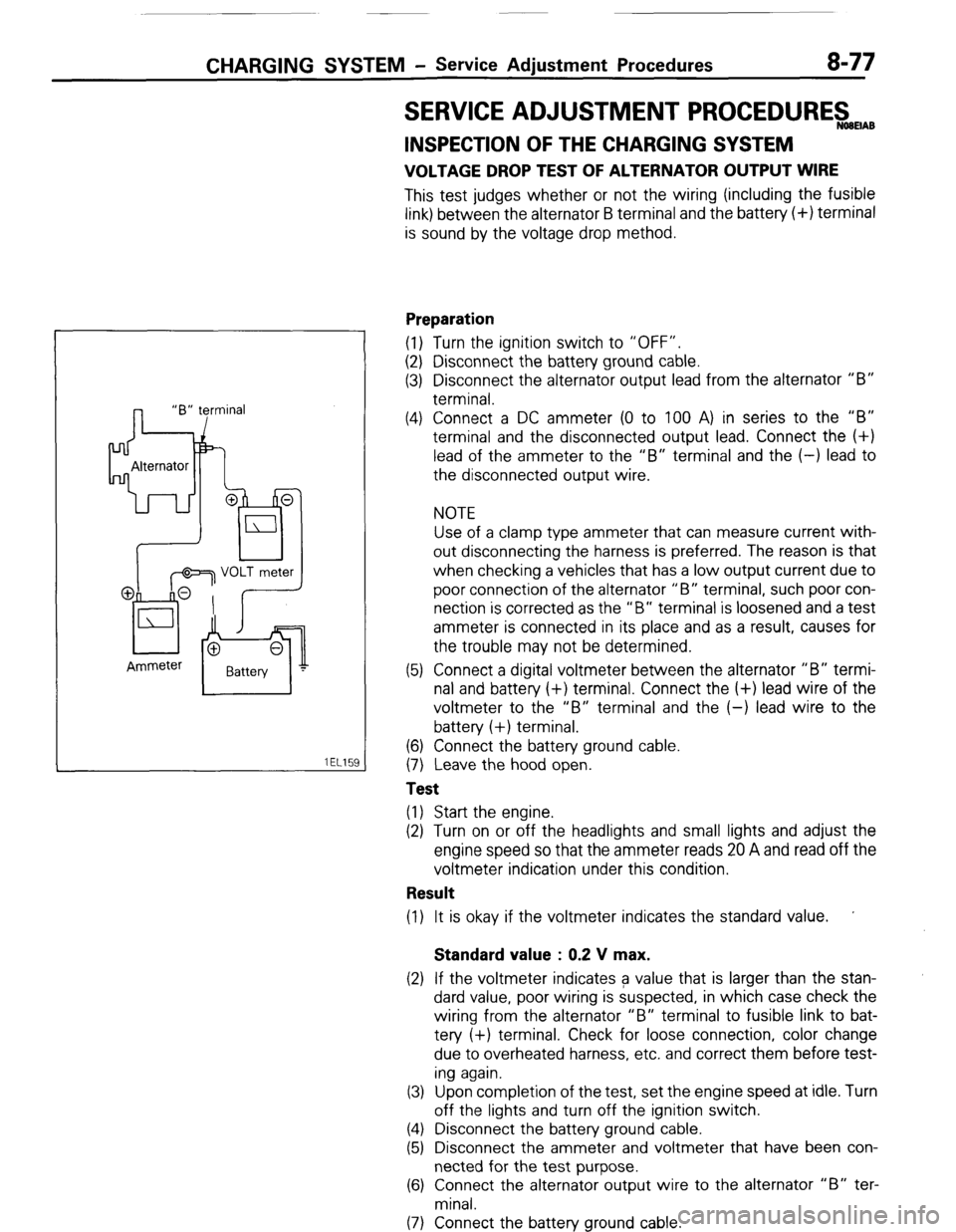
VOLTAGE DROP TEST OF ALTERNATOR OUTPUT WIRE
This test judges whether or not the wiring (including the fusible
link) between the alternator B terminal and the battery (+) terminal
is sound by the voltage drop method.
Preparation
(1) Turn the ignition switch to “OFF”.
(2) Disconnect the battery ground cable.
(3) Disconnect the alternator output lead from the alternator “B”
terminal.
(4) Connect a DC ammeter (0 to 100 A) in series to the “B”
terminal and the disconnected output lead. Connect the (+)
lead of the ammeter to the “B” terminal and the (-) lead to
the disconnected output wire.
NOTE
Use of a clamp type ammeter that can measure current with-
out disconnecting the harness is preferred. The reason is that
when checking a vehicles that has a low output current due to
poor connection of the alternator “B” terminal, such poor con-
nection is corrected as the “B” terminal is loosened and a test
ammeter is connected in its place and as a result, causes for
the trouble may not be determined.
(5) Connect a digital voltmeter between the alternator “B” termi-
nal and battery (+) terminal. Connect the (+) lead wire of the
voltmeter to the “B” terminal and the (-) lead wire to the
battery (+) terminal.
(6) Connect the battery ground cable.
(7) Leave the hood open.
Test
(1) Start the engine.
(2) Turn on or off the headlights and small lights and adjust the
engine speed so that the ammeter reads 20 A and read off the
voltmeter indication under this condition.
Result
(1) It is okay if the voltmeter indicates the standard value. ’
Standard value : 0.2 V max.
(2) If the voltmeter indicates a value that is larger than the stan-
dard value, poor wiring is suspected, in which case check the
wiring from the alternator “B” terminal to fusible link to bat-
tery (+) terminal. Check for loose connection, color change
due to overheated harness, etc. and correct them before test-
ing again.
(3) Upon completion of the test, set the engine speed at idle. Turn
off the lights and turn off the ignition switch.
(4) Disconnect the battery ground cable.
(5) Disconnect the ammeter and voltmeter that have been con-
nected for the test purpose.
(6) Connect the alternator output wire to the alternator “B” ter-
minal.
(7) Connect the battery ground cable.
( STB Revision
Page 98 of 284
8-78 CHARGING SYSTEM - Service Adiustment Procedures
80A
n
Relay with diode
Voltmeter
Ammeter Iad
176
OUTPUT CURRENT TEST
This test judges whether or not the alternator gives an output
current that is equivalent to the nominal output.
Preparation
(1) Prior to the test, check the following items and correct as
necessary.
(a) Check the battery installed in the vehicle to ensure that it
is in sound state*. The battery checking method is de-
scribed in “BATTERY”.
NOTE
*The battery that is used to test the output current should
be one that has been rather discharged. With a fully
charged battery, the test may not be conducted correctly
due to an insufficient load.
(b) Check tension of the alternator drive belt. The belt tension
check method is described in “GROUP 7 COOLING -
Service Adjustment Procedures”.
(2) Turn off the ignition switch.
(3) Disconnect the battery ground cable.
(4) Disconnect the alternator output wire from the alternator “B”
terminal.
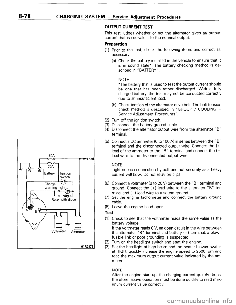
(5) Connect a DC ammeter (0 to 100 A) in series between the “B”
terminal and the disconnected output wire. Connect the (+)
lead of the ammeter to the “B” terminal and connect the (-)
lead wire to the disconnected output wire.
NOTE
Tighten each connection by bolt and nut securely as a heavy
current will flow. Do not relay on clips.
(6) Connect a voltmeter (0 to 20 V) between the “B” terminal and
ground. Connect the (+) lead wire to the alternator “B” ter-
minal and (-) lead wire to a sound ground.
(7) Set the engine tachometer and connect the battery ground
cable.
(8) Leave the engine hood open.
Test
(1) Check to see that the voltmeter reads the same value as the
battery voltage.
If the voltmeter reads 0 V, an open circuit in the wire between
the alternator “B” terminal and battery (-) terminal, a blown
fusible link or poor grounding is suspected.
(2) Turn on the headlight switch and start the engine.
(3) Set the headlight at high beam and the heater blower switch
at HIGH, quickly increase the engine speed to 2500 rpm and
read the maximum output current value indicated by the am-
meter.
NOTE
After the engine start up, the charging current quickly drops.
therefore, above operation must be done quickly to read max-
imum current value correctly.
[ STB Revision
--I
Page 99 of 284
CHARGING SYSTEM - Service Adjustment Procedures 8-79
Result
(1) The ammeter reading must be higher than the limit value. If it
is lower but the alternator output wire is normal, remove the
alternator from the vehicle and check it.
Limit value : 31 A min.
Caution
1. The nominal output current value is shown on the
nameplate affixed to the alternator body.
2. The output current value changes with the electrical
load and the temperature of the alternator itself.
Therefore, the nominal output current may not be ob-
tained if the vehicle electrical load at the time of test is
small. In such a case, keep the headlights on to cause
discharge of the battery or use lights of another vehi-
cle as a load to increase the electrical load. The nom-
inal output current may not be obtained if the temper-
ature of the alternator itself or abmient temperature is
too high. In such a case, reduce the temperature be-
fore testing again.
(2) Upon completion of the output current test, lower the engine
speed to the idle speed and turn off the ignition switch.
(3) Disconnect the battery ground cable.
(4) Remove the test ammeter and voltmeter and the engine ta-
chometer.
(5) connect the alternator output wire to the alternator “B” ter-
minal.
(6) Connect the battery ground cable.
REGULATED VOLTAGE TEST
The purpose of this test is to check that the electronic voltage
regulator controls the voltage correctly.
Preparation
(1) Prior to the test, check the following items and correct if nec-
essary.
(a) Check the battery installed on the vehicle to see that it is
fully charged. For battery checking method, see “BAT-
TERY”.
(b) Check the alternator drive belt tension. For belt tension
check, see “GROUP 7 COOLING - Service Adjustment
Procedures”.
(2) Turn the ignition switch to “OFF”.
(3) Disconnect the battery ground cable.
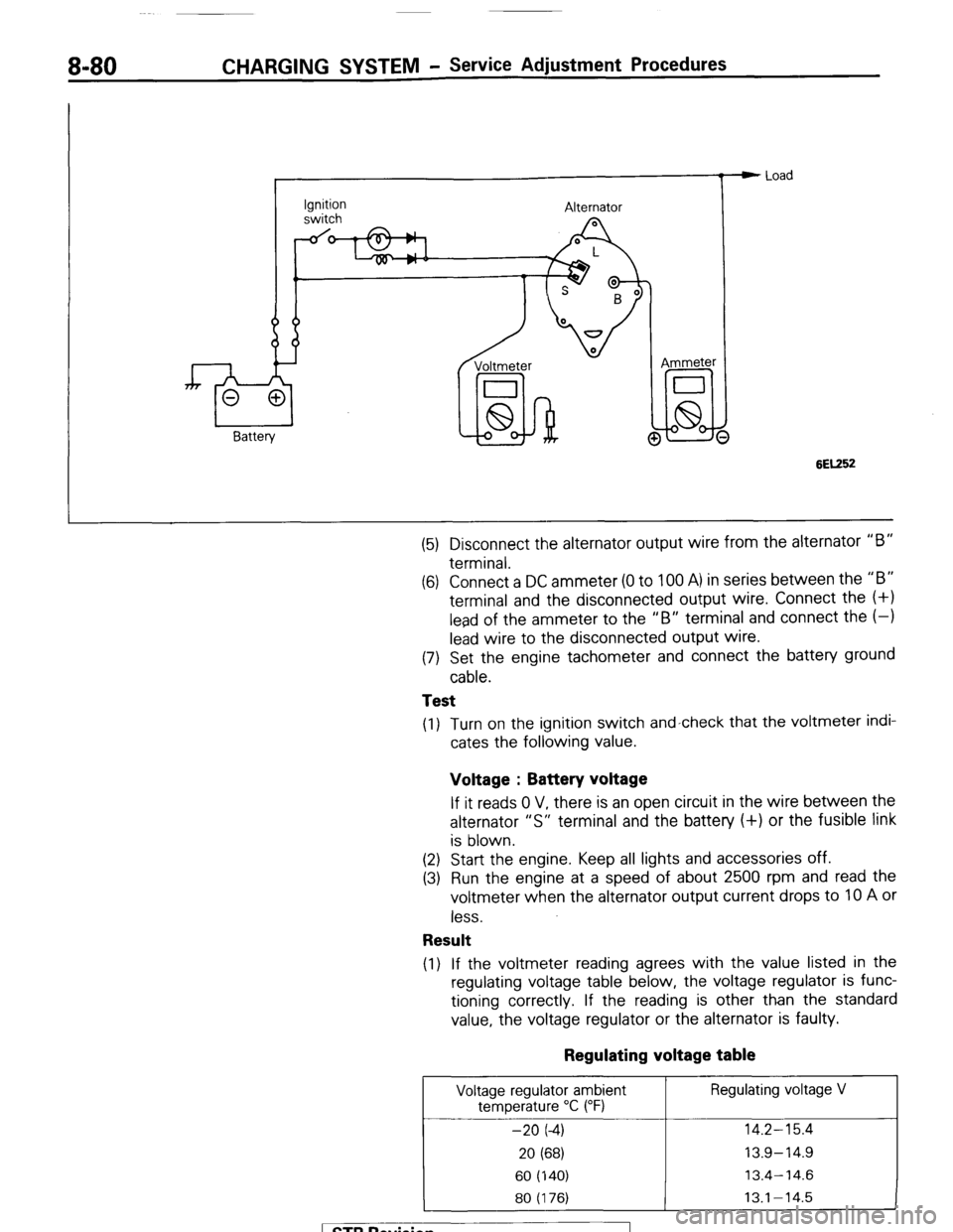
(4) Connect a digital voltmeter between the “S” terminal of the
alternator and ground. Connect the (+) lead of the voltmeter to
the “S” terminal of the alternator, inserting from the wire side
of the 2-way connector and connect the (-1 lead to sound
ground or battery (-) terminal.
1 ST6 Revision
Page 100 of 284
8-80 CHARGING SYSTEM - Service Adjustment Procedures
Ignition
switch Alternator
Voltmeter
I
lid-hi! @ Ammeter e Load
6EK52
(5) Disconnect the alternator output wire from the alternator “B”
terminal.
(6) Connect a DC ammeter (0 to 100 A) in series between the “B”
terminal and the disconnected output wire. Connect the (+I
lead of the ammeter to the “B” terminal and connect the (-1
lead wire to the disconnected output wire.
(7) Set the engine tachometer and connect the battery ground
cable.
Test
(1) Turn on the ignition switch and-check that the voltmeter indi-
cates the following value.
Voltage : Battery voltage
If it reads 0 V, there is an open circuit in the wire between the
alternator “S” terminal and the battery (+) or the fusible link
is blown.
(2) Start the engine. Keep all lights and accessories off.
(3) Run the engine at a speed of about 2500 rpm and read the
voltmeter when the alternator output current drops to 10 A or
less.
Result
(1) If the voltmeter reading agrees with the value listed in the
regulating voltage table below, the voltage regulator is func-
tioning correctly. If the reading is other than the standard
value, the voltage regulator or the alternator is faulty.
Regulating voltage table
Voltage regulator ambient Regulating voltage V
temperature “C (“F)
-20 (-4) 14.2-15.4
20 (68) 13.9-14.9
60 (140) 13.4-14.6
80 (176) 13.1-14.5
1 STB Revision
Page 101 of 284
CHARGING SYSTEM - Service Adjustment Procedures 8-81
(2) Upon completion of the test, set the engine speed at idle and
turn off the ignition switch.
(3) Disconnect the battery ground cable.
(4) Remove the test voltmeter and ammeter and the engine ta-
chometer.
(5) Connect the alternator output wire to the alternator “B” ter-
minal.
(6) Connect the battery ground cable.
ll3Y1848 2. Remove battery from vehicle.
Caution
White
I Blue
I Care should be taken in the event battery case is cracked
or leaking to protect hands from the electrolyte. A suit-
able pair of rubber gloves (not the household type) should
be worn when removing battery by hand.
3. Inspect battery carrier for damage caused by loss of acid from
battery. If acid damage is present, it will be necessary to clean
area with a solution of clean warm water and baking soda.
Scrub area with a stiff bristle brush and wipe off with a cloth
moistened with ammonia or baking soda in water.
4. Clean top of battery with same solutions as described in Step
(3).
INSPECTION OF BATTERY NOBEIBA
VISUAL INSPECTION OF BATTERY (1)
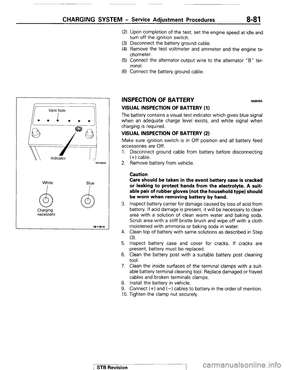
The batten/ contains a visual test indicator which gives blue signal
when an adequate charge level exists, and white signal when
charging is required.
VISUAL INSPECTION OF BAlTERY (2)
Make sure ignition switch is in Off position and all battery feed
accessories are Off.
1. Disconnect ground cable from battery before disconnecting
(+) cable.
5. Inspect battery case and cover for cracks. If cracks are
present, battery must be replaced.
6. Clean the battery post with a suitable battery post cleaning
tool.
7. Clean the inside surfaces of the terminal clamps with a suit-
able battery terminal cleaning tool. Replace damaged or frayed
cables and broken terminals clamps.
8. Install the battery in vehicle.
9. Connect (+) and (-) cables to battery in the order of mention.
10. Tighten the clamp nut securely.
1 STB Revision
Page 103 of 284
CHARGING SYSWVI - Alternator 8-83
ALTERNATOR
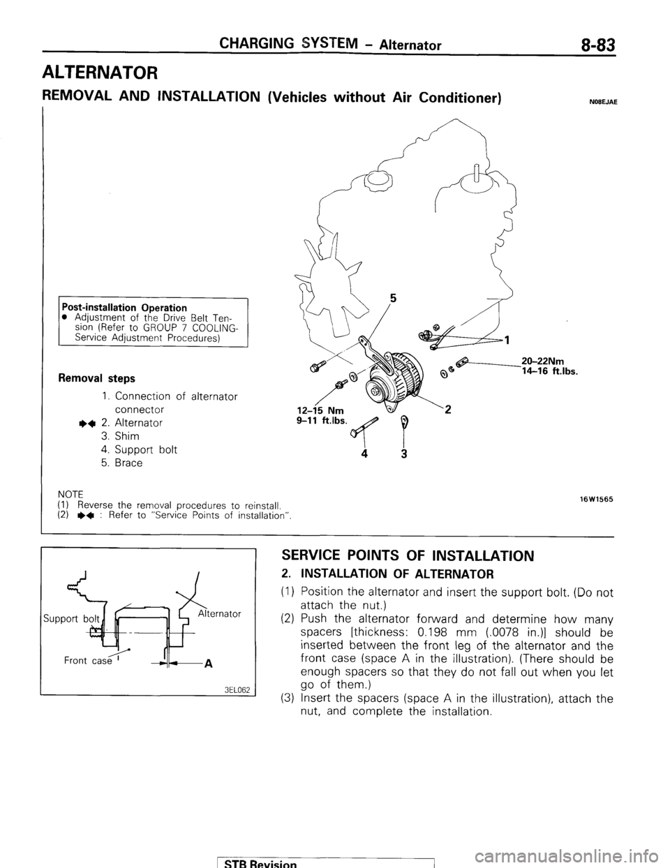
REMOVAL AND INSTALLATION (Vehicles without Air Conditioner) NOEEJAE
0 Adjustment of the Drive Belt Ten-
slon (Refer to GROUP 7 COOLING-
Service Adjustment Procedures)
Removal steps
1. Connection of alternator
connector
I)+ 2. Alternator
3. Shim
4.
Support bolt
5.
Brace
9-11 ft.lbs. 9
4
3
NOTE
(I) Reverse the removal procedures to reinstall.
(2) l * : Refer to “Service Points of installation”. 16W1565
SERVICE POINTS OF INSTALLATION
2. INSTALLATION OF ALTERNATOR
(1) Position the alternator and insert the support bolt. (Do not
attach the nut.)
(2) Push the alternator forward and determine how many
spacers [thickness: 0.198 mm (.0078 in.)] should be
inserted between the front leg of the alternator and the
front case (space A in the illustration). (There should be
enough spacers so that they do not fall out when you let
go of them.)
(3) Insert the spacers (space A in the illustration), attach the
nut, and complete the installation.
ST6 Revision
Page 104 of 284
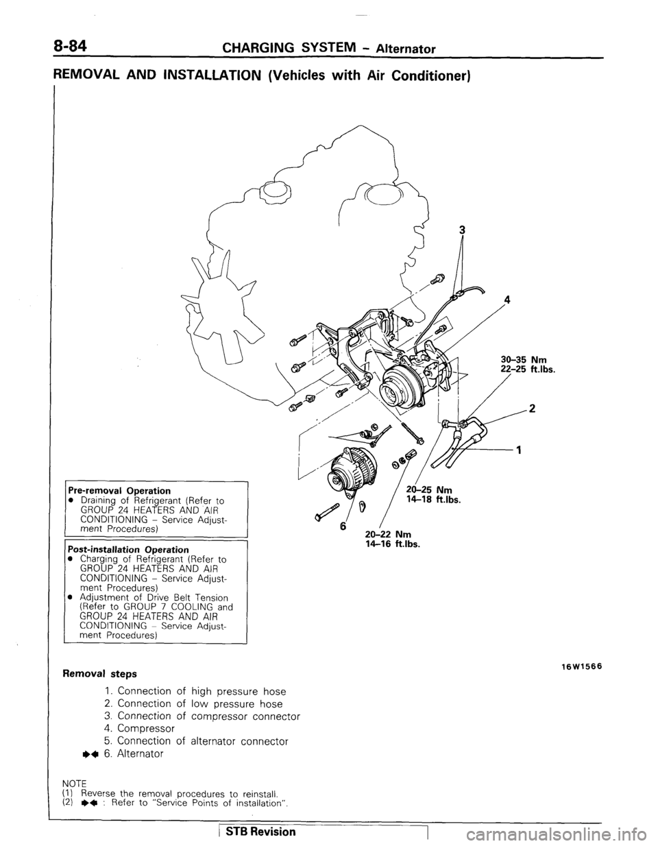
8-84 CHARGING SYSTEM - Alternator
REMOVAL AND INSTALLATION (Vehicles with Air Conditioner)
30-35 Nm
20-22 Nm
14-16 ft.lbs. D Draining of Refrigerant (Refer to
CONDITIONING - Service Adjust-
1 ‘ost-installation Operation
1 Charging of Refrigerant (Refer to
GROUP 24 HEATERS AND AIR
CONDITIONING - Service Adjust-
ment Procedures)
D Adjustment of Drive Belt Tension
(Refer to GROUP 7 COOLING and
GROUP 24 HEATERS AND AIR
CONDITIONING ~ Service Adjust-
ment Procedures)
:emoval steps
1. Connection of high pressure hose
2. Connection of low pressure hose
3. Connection of compressor connector
4. Compressor
5. Connection of alternator connector
~~ 6. Alternator
OTE
) Reverse the removal procedures to reinstall.
I) e+ : Refer to “Service Points of installation” 16W1566
/ STB Revision
Page 105 of 284
CHARGING SYSTEM - Alternator 8-85
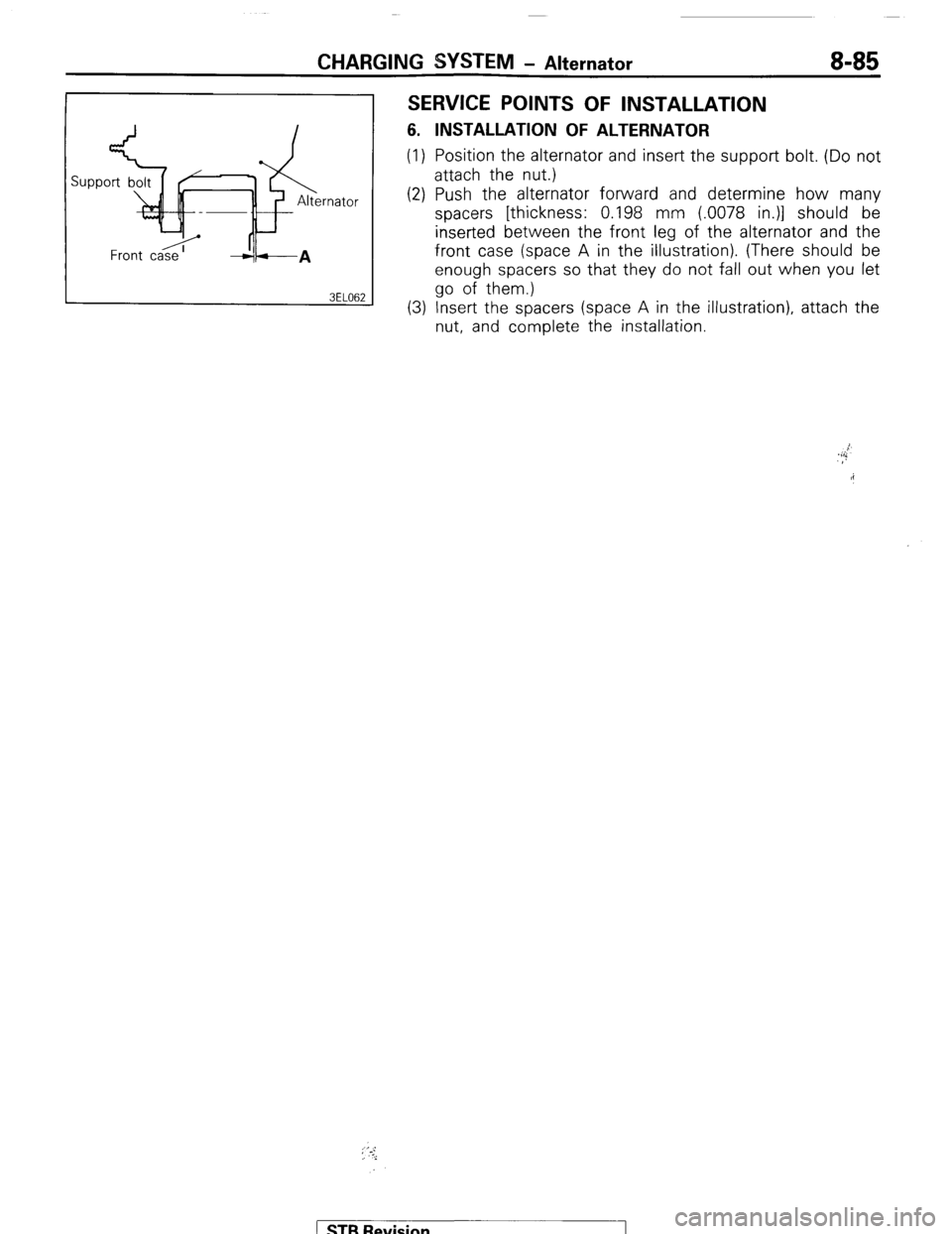
SERVICE POINTS OF INSTALLATION
6. INSTALLATION OF ALTERNATOR
(1) Position the alternator and insert the support bolt. (Do not
attach the nut.)
(2) Push the alternator forward and determine how many
spacers [thickness: 0.198 mm (.0078 in.)] should be
inserted between the front leg of the alternator and the
front case (space A in the illustration). (There should be
enough spacers so that they do not fall out when you let
go of them.)
(3) Insert the spacers (space A in the illustration), attach the
nut, and complete the installation.
; ‘.-:,
i
) STB Revision