Oil pressure sensor MITSUBISHI MONTERO 1987 1.G Workshop Manual
[x] Cancel search | Manufacturer: MITSUBISHI, Model Year: 1987, Model line: MONTERO, Model: MITSUBISHI MONTERO 1987 1.GPages: 284, PDF Size: 14.74 MB
Page 21 of 284

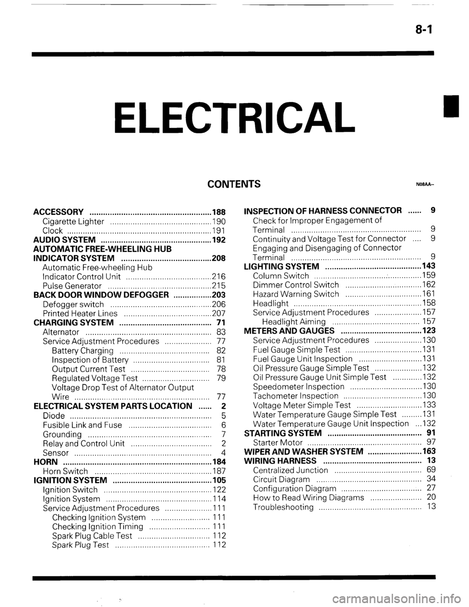
8-1
ELECTRICAL
CONTENTS
NOBAA-
ACCESSORY ......................................................
188
Cigarette Lighter ............................................
,190
Clock ...............................................................
,191
AUDIO SYSTEM ................................................
.192
AUTOMATIC FREE-WHEELING HUB
INDICATOR SYSTEM ........................................
208
Automatic Free-wheeling Hub
Indicator Control Unit
..................................... ,216
Pulse Generator ..............................................
215
BACK DOOR WINDOW DEFOGGER
................ .203
Defogger switch ............................................
,206
Printed Heater Lines
...................................... ,207
CHARGING SYSTEM .........................................
71
Alternator ........................................................
83
Service Adjustment Procedures
..................... 77
Battery Charging ........................................
82
Inspection of Battery ..................................
81
Output Current Test ...................................
78
Regulated Voltage Test ..............................
79
Voltage Drop Test of Alternator Output
Wire ............................................................
77
ELECTRICAL SYSTEM PARTS LOCATION
...... 2
Diode ...............................................................
5
Fusible Link and Fuse
..................................... 6
Grounding .......................................................
7
Relay and Control Unit ....................................
2
Sensor .............................................................
4
HORN ..................................................................
184
Horn Switch
.................................................... 187
IGNITION SYSTEM ............................................
105
Ignition Switch
................................................ 122
Ignition System ...............................................
1 14
Service Adjustment Procedures
.................... .l 1 1
Checking Ignition System
..........................
11 1
Checking Ignition Timing
...........................
11 1
Spark Plug Cable Test
................................
1 12
Spark Plug Test
.......................................... 1 12 INSPECTION OF HARNESS CONNECTOR ...... 9
Check for Improper Engagement of
Terminal .......................................................... 9
Continuity and Voltage Test for Connector .... 9
Engaging and Disengaging of Connector
Terminal ..........................................................
9
LIGHTING SYSTEM ........................................... 143
Column Switch
................................ .
.............. .I59
Dimmer Control Switch
................................. .I62
Hazard Warning Switch
................................. .I61
Headlight ........................................................ ,158
Service Adjustment Procedures
.................... .I57
Headlight Aiming .......................................
157
METERS AND GAUGES .................................... 123
Service Adjustment Procedures
.................... .I30
Fuel Gauge Simple Test ................................. .I31
Fuel Gauge Unit Inspection ........................... .I31
Oil Pressure Gauge Simple Test
.................... .I32
Oil Pressure Gauge Unit Simple Test
............ ,132
Speedometer Inspection
............................... .I30
Tachometer Inspection .................................. ,130
Voltage Meter Simple Test
............................ .I33
Water Temperature Gauge Simple Test
....... ..I3 1
Water Temperature Gauge Unit Inspection
. ..I3 2
STARTING SYSTEM .......................................... 91
Starter Motor ............ ....................................... 97
WIPER AND WASHER SYSTEM
....................... .163
WIRING HARNESS ............................................ 13
Centralized Junction ....................................... 69
Circuit Diagram ............................................... 34
Configuration Diagram .................................... 27
How to Read Wiring Diagrams ....................... 20
Troubleshooting .............................................. 13
Page 49 of 284

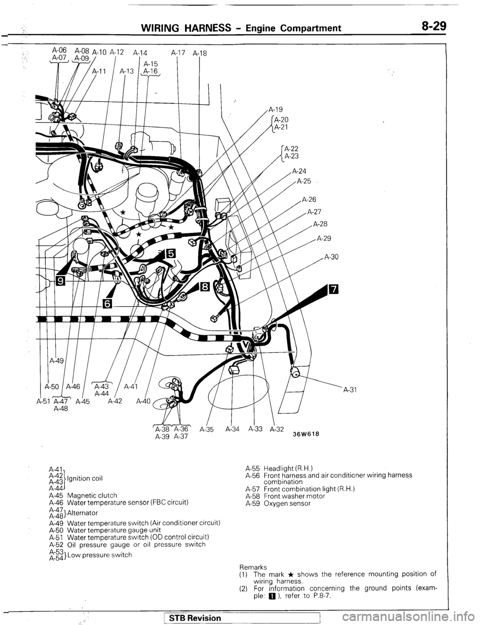
WIRING- HARNESS - Engine Compartment 8-29
; A-06 A-08 A-1 0 A-12 A-14
,.
1 A-15 8
I I
,I I I, I /
A-48
WI
&-ii& ’
A-35 Ai34 A!33 J-3:
A-39 A-37
36W618
A41
i-$ Ignition coil
A-44
A-45 Magnetic clutch
A-46 Water temperature sensor (FBC circuit)
;rii}Alternator
A-49 Water temperature switch (Air conditioner circuit)
A-50 Water temperature gauge unit
A-51 Water temperature switch (OD control circuit)
A-52 Oil pressure gauge or oil pressure switch
$3 Low pressure switch A-55 Headlight (R.H.)
A-56 Front harness and air conditioner wiring harness
combination
A-57 Front combination light (R.H.)
A-58 Front washer motor
A-59 Oxygen sensor
Remarks
(1) The mark * shows the reference mounting position of
wiring harness.
(2) For information concerning the ground points (exam-
ple:
q ), refer to P.8-7.
1 STB Revision
Page 73 of 284

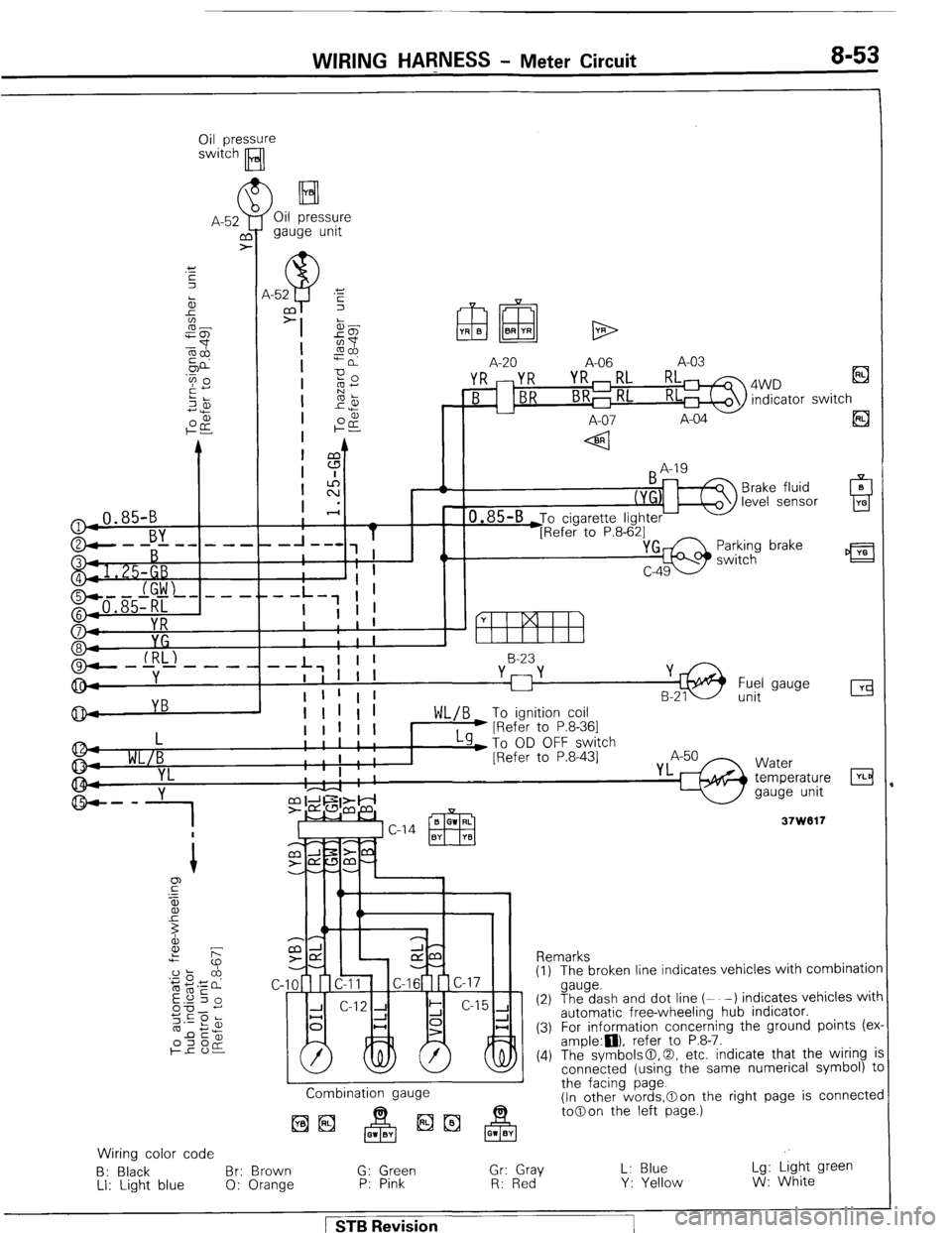
WIRING HAFNESS - Meter Circuit 8-53
O&y-ssure
[Eal
* - -,,- - - - -
YB
> El Oil pressure
gauge unit
ElxQ YR B BR YR
I.+
A-20
A-06 A-03
4WD Ei
indicator switch
A-07 A-04 I r-
’ fs A
I I
I
E
1 ,’
-I T
-- m-w
I ? I
I I ’
k-1 1 I
.- -
I
I ' 1
I I
I I I I 4
0.85-B Jo
cigarette lighter
[Refer to P.8-621 Brake fluid
level sensor
Parking brake
switch
L, I I 1 B-23
-- I , I I I
I !
Fuel gauge
unit
Water
temperature
gauge unit
37W617
les with combinatior
(2) %?zgdeash and dot line (- -) indicates vehicles wit1
automatic free-wheeling hub indicator.
(3) For information concerning the ground points (er
ample:n), refer to P.8-7.
(4) The symbols@,@, etc. indicate that the wiring i
connected (using the same numerical symbol) tl
Combination gauge the facing page.
(In other words,Oon the right page is connecter
to@on the left page.)
Wiring color code
B: Black Br: Brown G: Green Gr: Gray L: Blue Lg: Light green
LI: Light blue 0: Orange P: Pink R: Red Y: Yellow W: White
1 STB Revision
Page 256 of 284

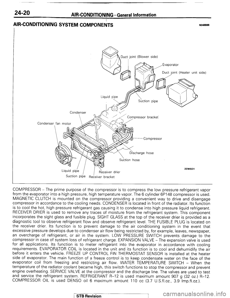
24-20 AIR-CONDITION!NG-General Information
I
AIR-CONDITIONING SYSTEM COMPO
N24BBBB
Condenser MDuct, joint (Blower side)
oint (Heater unit
Condenser
2OWB31
Suction Pipe Receiver bracket side)
COMPRESSOR - The prime purpose of the compressor is to compress the low pressure refrigerant vapor
from the evaporator into a high pressure, high temperature vapor. The 6 cylinder 6P148 compressor is used.
MAGNETIC CLUTCH is mounted on the compressor providing a convenient way to drive and disengage
compressor in accordance to the cooling needs. CONDENSER is located in front of the radiator. Its function
is to cool the hot, high pressure refrigerant gas causing it to condense into high pressure liquid refrigerant.
RECEIVER DRIER is used to remove any traces of moisture from the refrigerant system. This component
incorporates the sight glass and fusible plug. SIGHT GLASS at the top of the receiver drier is provided as a
diagnostic tool to observe refrigerant flow and observe refrigerant level. THE FUSIBLE PLUG is located on
the receiver drier. Its function is to prevent damage to the air conditioning system in the event that
excessive pressure develops due to condenser air flow being restricted by, for example, leaves, newspaper,
an overcharge of refrigerant, or air in the system. LOW PRESSURE SWITCH prevents damage to the
compressor in case of system loss of refrigerant charge. EXPANSION VALVE - The expansion valve is used
for all applications. Its function is to meter refrigerant into the evaporator in accordance with cooling
requirements. EVAPORATOR COIL is located in the unit and its function is to cool and dehumidify the air
before it enters the vehicle. FREEZE UP CONTROL FIN THERMOSTAT SENSOR is installed at the heater
side of evaporator. The main function of a freeze control is to keep condensate water on the face of the
evaporator coil from freezing and restricting air flow. WATER TEMPERATURE SWITCH - When the
temperature of the radiator coolant became high, this switch functions to stop the compressor and prevent
engine overheating. SERVICE VALVE at the compressor and the discharge line. The valves are used to test
and service the refrigerant system. REFRIGERANT R-12 is used maximum amount 907 g (32 oz.) R-12.
COMPRESSOR OIL is used DENS0 oil 6 maximum amount 110 cc (3.7 U.S.fl.oz., 3.9 Imp.fl.oz.).
/ STB Revision