fuse diagram MITSUBISHI MONTERO 1987 1.G Workshop Manual
[x] Cancel search | Manufacturer: MITSUBISHI, Model Year: 1987, Model line: MONTERO, Model: MITSUBISHI MONTERO 1987 1.GPages: 284, PDF Size: 14.74 MB
Page 21 of 284
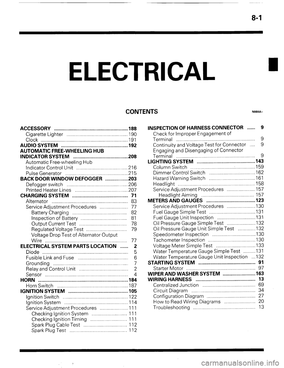
8-1
ELECTRICAL
CONTENTS
NOBAA-
ACCESSORY ......................................................
188
Cigarette Lighter ............................................
,190
Clock ...............................................................
,191
AUDIO SYSTEM ................................................
.192
AUTOMATIC FREE-WHEELING HUB
INDICATOR SYSTEM ........................................
208
Automatic Free-wheeling Hub
Indicator Control Unit
..................................... ,216
Pulse Generator ..............................................
215
BACK DOOR WINDOW DEFOGGER
................ .203
Defogger switch ............................................
,206
Printed Heater Lines
...................................... ,207
CHARGING SYSTEM .........................................
71
Alternator ........................................................
83
Service Adjustment Procedures
..................... 77
Battery Charging ........................................
82
Inspection of Battery ..................................
81
Output Current Test ...................................
78
Regulated Voltage Test ..............................
79
Voltage Drop Test of Alternator Output
Wire ............................................................
77
ELECTRICAL SYSTEM PARTS LOCATION
...... 2
Diode ...............................................................
5
Fusible Link and Fuse
..................................... 6
Grounding .......................................................
7
Relay and Control Unit ....................................
2
Sensor .............................................................
4
HORN ..................................................................
184
Horn Switch
.................................................... 187
IGNITION SYSTEM ............................................
105
Ignition Switch
................................................ 122
Ignition System ...............................................
1 14
Service Adjustment Procedures
.................... .l 1 1
Checking Ignition System
..........................
11 1
Checking Ignition Timing
...........................
11 1
Spark Plug Cable Test
................................
1 12
Spark Plug Test
.......................................... 1 12 INSPECTION OF HARNESS CONNECTOR ...... 9
Check for Improper Engagement of
Terminal .......................................................... 9
Continuity and Voltage Test for Connector .... 9
Engaging and Disengaging of Connector
Terminal ..........................................................
9
LIGHTING SYSTEM ........................................... 143
Column Switch
................................ .
.............. .I59
Dimmer Control Switch
................................. .I62
Hazard Warning Switch
................................. .I61
Headlight ........................................................ ,158
Service Adjustment Procedures
.................... .I57
Headlight Aiming .......................................
157
METERS AND GAUGES .................................... 123
Service Adjustment Procedures
.................... .I30
Fuel Gauge Simple Test ................................. .I31
Fuel Gauge Unit Inspection ........................... .I31
Oil Pressure Gauge Simple Test
.................... .I32
Oil Pressure Gauge Unit Simple Test
............ ,132
Speedometer Inspection
............................... .I30
Tachometer Inspection .................................. ,130
Voltage Meter Simple Test
............................ .I33
Water Temperature Gauge Simple Test
....... ..I3 1
Water Temperature Gauge Unit Inspection
. ..I3 2
STARTING SYSTEM .......................................... 91
Starter Motor ............ ....................................... 97
WIPER AND WASHER SYSTEM
....................... .163
WIRING HARNESS ............................................ 13
Centralized Junction ....................................... 69
Circuit Diagram ............................................... 34
Configuration Diagram .................................... 27
How to Read Wiring Diagrams ....................... 20
Troubleshooting .............................................. 13
Page 43 of 284
WIRING HARNESS - HOW BO Read Wiring Diagrams 8-23
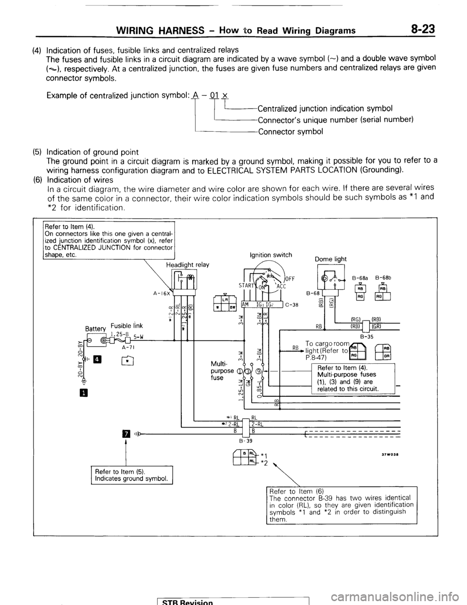
(4) Indication of fuses, fusible links and centralized relays
The fuses and fusible links in a circuit diagram are indicated by a wave symbol (-) and a double wave symbol
(~1, respectively. At a centralized junction, the fuses are given fuse numbers and centralized relays are given
connector symbols.
Example of centralized junction symbol: A - 01 x
Centralized junction indication symbol
Connector’s unique number (serial number)
Connector symbol
(5) Indication of ground point
The ground point in a circuit diagram is marked by a ground symbol, making it possible for you to refer to a
wiring harness configuration diagram and to ELECTRICAL SYSTEM PARTS LOCATION (Grounding).
(6) Indication of wires
In a circuit diagram, the wire diameter and wire color are shown for each wire. If there are several wires
of the same color in a connector, their wire color indication symbols should be such symbols as “I and
“2 for identification.
On connectors like this one given a central-
to CENTRALIZED JUNCTION for connector
1 shaoe. etc.
-I Headlight relay ignition switch
Dome light
I II I B-35 B-68b
P:8-47)
IEU
I ’ 2 I
RL
2-RL
0 III- BI B -----____________
L - - - - - _ _ _ _ _ __ _ _ _ _ _
B-39
Refer to Item (5).
Refer to Item (6)
The connector B-39 has two wires identical
in color (RL), so they are given identification
symbols *I and *2 in order to distinguish
them. 1 ST6 Revision
Page 46 of 284
8-26 WIRING HARNESS - HOW to Read Wiring Diagrams
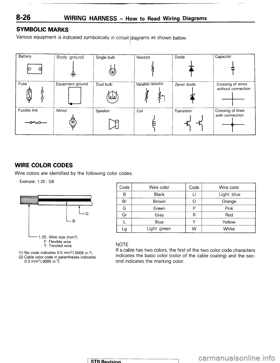
SYMBOLIC MARKS
Various equipment is indicated symbolically in circuit idiagrams as shown below.
Battery Body ground Single bulb Resistor Diode Capacitor
Fuse Equipment ground
Fusible link
Motor
Speaker Coil ~
4 Transistor Crossing of lines
4 -1~ with conron
WIRE COLOR CODES Wire colors are identified by the following color codes.
Example: 1.25 - GB Code Wire color Code Wire color
B
Br Black
Brown LI
0 Light blue
Oranqe
I P
i 1 Gr 1 Grav 1 R 1 Red I
I L I Blue
I Y I Yellow I
L 1.25: Wire size (mm2)
F: Flexible wire
T: Twisted wire
(1) No code indicates 0.5 mm2(.0008 in.*).
(2) Cable color-code in parantheses indicates
0.3 mm* (.0005 in.‘).
Lg Light green W White
NOTE
If a cable has two colors, the first of the two color code characters
indicates the basic color (color of the cable coating) and the sec-
ond indicates the marking color.
STB Revision
Page 169 of 284
LIGHTING SYSTEM - Circuit Diagram 8-149
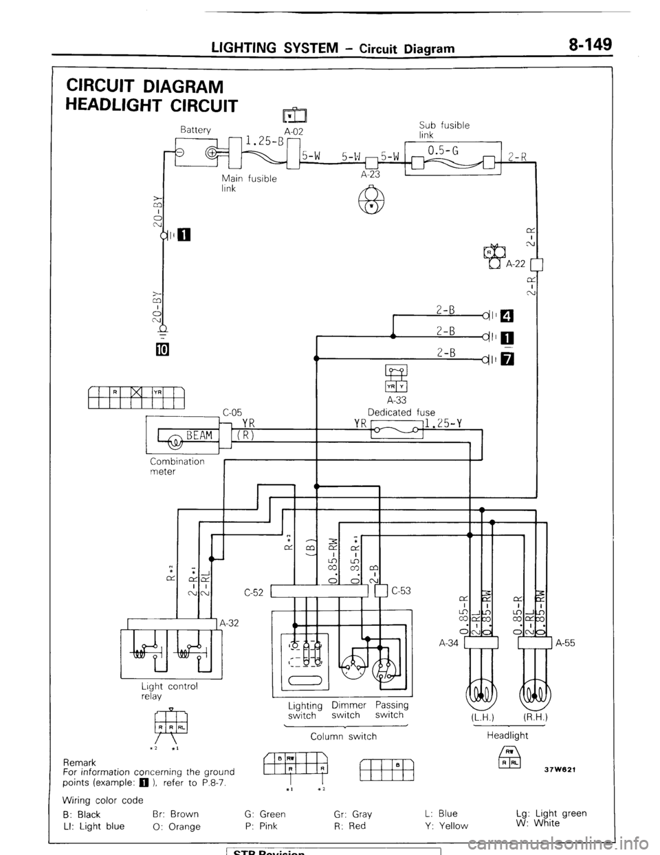
CIRCUIT DIAGRAM
HEADLIGHT CIRCUIT m
Battery
A-02 Sub fusible
link
0.5-G
5-v m5-w m 2-R
L-l
Main fusible A-23
lrnk
z
A
2-B
dl
r 2-B
I dl
ItfYH
A-33
c-05 Dedicated fuse
YR[ 11.25-Y
1-1
I
Combination
meter
I I
Wlir,L n
*
7
.-32 A
I
A-55
I
Lighting Dimmer Passing
switch switch switch
Column switch Lrght control
relay
FP R R RL
x2 XI
J
(LTH.) (R.H.)
Headlight
37W621 Remark
For information concerning the ground
points (example:
q ), refer to P.8-7.
Wiring color code
B: Black Br: Brown G: Green Gr: Gray
LI: Light blue 0: Orange P: Pink R: Red L: Blue
Y: Yellow Lg: Light green
W: White
/ STB Revision
Page 172 of 284
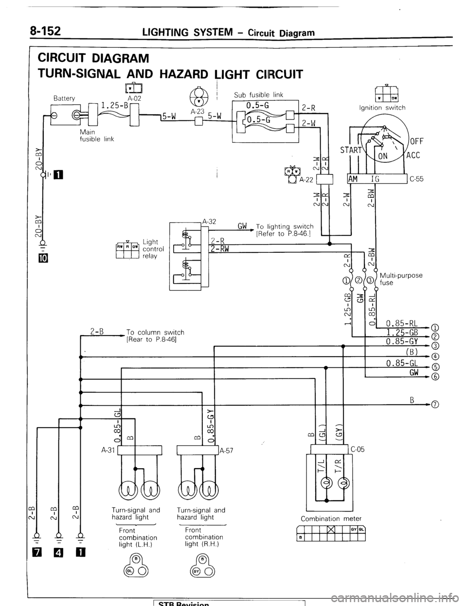
8-152 LIGHTING SYSTEM - Circuit Diagram
CIRCUIT DIAGRAM
TURN-SIGNAL AND HAZARD LIGHT CIIRCUIT
lml I Battery A-02 -1.25-B- 63 Sub fusible link 1 m 1 BI
Ignition switch
Main
fusible link
I 1
.I
-
z
I I I ’ I
Multi-purpose
fuse
0.85-RL
2-B
To column switch
[Rear to P.8-461 I 1.25-GB )
a
I 'I 0.85-GY o
I_
(BJ -0 0.85-GL -o
I Gw -@
3
cs
I
z
dm
A-31 1
Turn-signal and
hazard light Turn-signal and
hazard light
Front
combination Combination meter
w I I I GY a. q Front
combination
light (R.H.)
000
light (L.H.)
1 STB Revision 1
Page 175 of 284
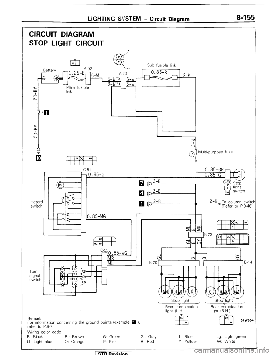
LIGHTING SYSTEM - Circuit Diagram 8-155
CIRCUIT DIAGRAM
STOP LIGHT CIRCUIT
Main fusible
link
Hazard
switch
Turn-
signal
switch Sub fusible link
-1 3-w
07 Multr-purpose fuse
c-51
-0.85-G
0.85-WG 2-B
To column switcf
*[Refer to P.8-461
Remark
For information concerning the ground points (example:
q ).
refer to P.8-7.
d B-20 1 ]B-14
Stop light ~
1 Stop light
Rear cdmbination
light (L.H.) Rear c;mbination
light (R.H.)
Wiring color code
B: Black Br: Brown G: Green Gr: Gray L: Blue Lg: Light green
Ll: Light blue 0: Orange P: Pink R: Red Y. Yellow W: White
1 STB Revision
Page 176 of 284
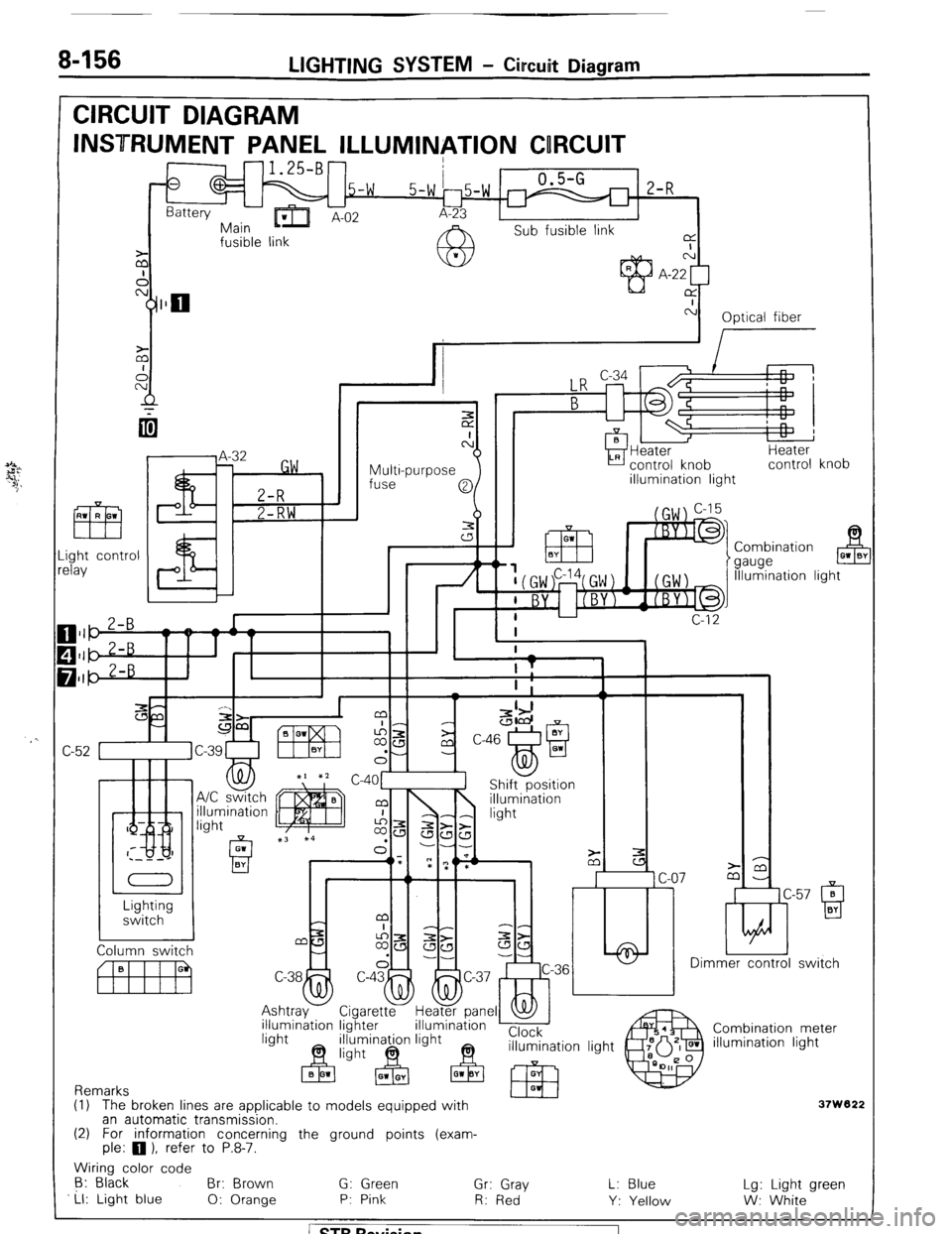
8-156 LIGHTING SYSTEM - Circuit Diagram
CIRCUIT DIAGRAM
INSTRUMENT PANEL ILLUMINATION CORCUIT
-1.25-B-
0
.5-w 0.5-G
2-R
Battery
-Err
5-w 15-w r
Main ’ A-02 A-23
Sub fusible link
fusible link a
I
z N
A A-22 [
cy]llo CY
c-i
Optical fiber
I
Multi-purpose
fuse Heater
control knob
illumination light Heater
control knob
ght control
lay Combination
gauge B 01 0’
Illumination light
/ n
c
C
-
c-57 0 ti
Q BY Lighting
switch
Dimmer control switch
rel
Combination meter
illumination light illumination lighter
Remarks
(1) The broken lines are applicable to models eouipped with
37W822 an automatic transmission.
(2) For information concerning the ground points (exam-
ple: 0 1, refer to P.8-7.
Wiring color code
6: Black
Br: Brown G: Green
Ll: Light blue Gr: Gray
0: Orange P: Pink
R: Red L: Blue
Y: Yellow Lg: Light green
W: White 1 ST6 Revision
Page 188 of 284
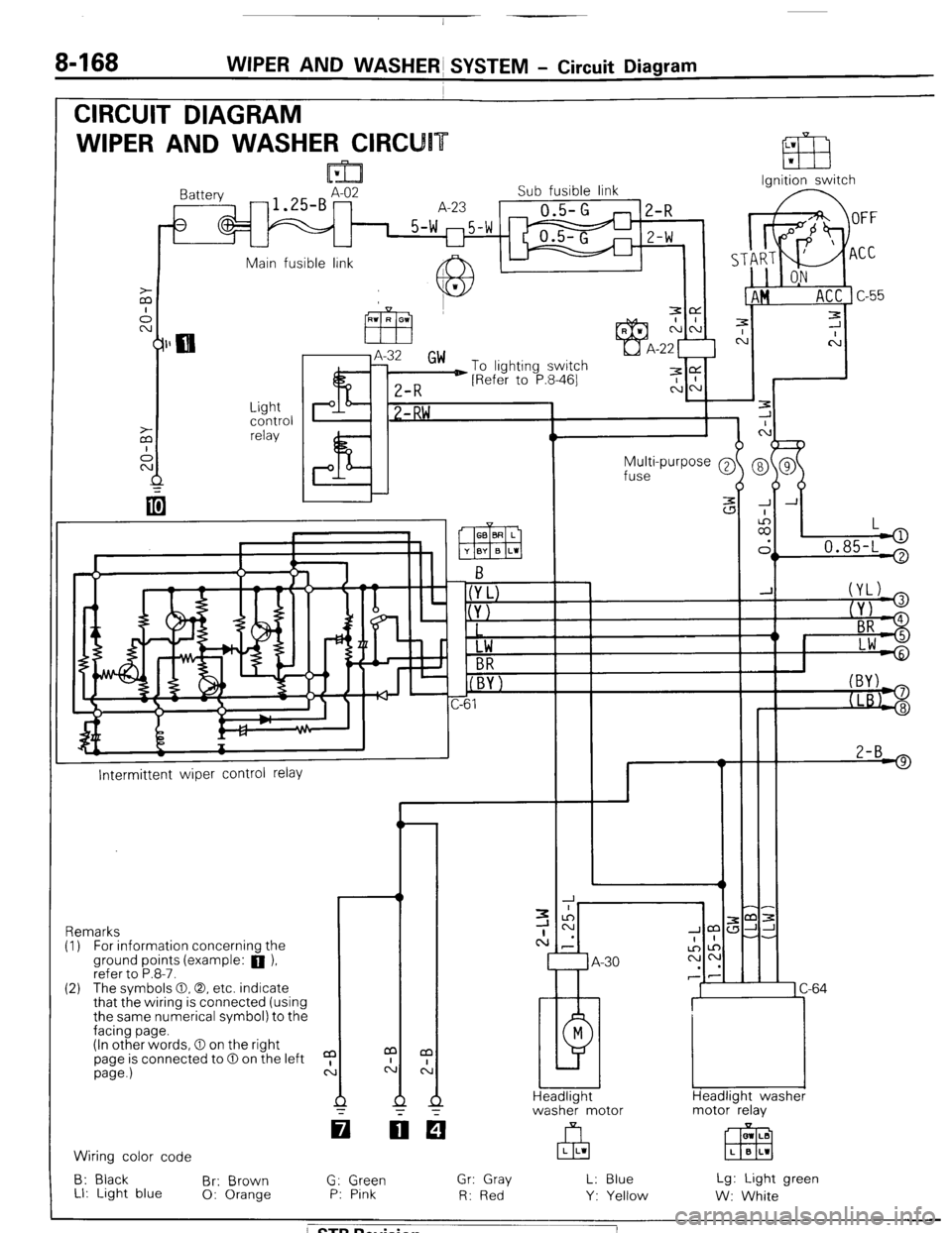
8468 WIPER AND WASHERS SYSTEM - Circuit Diagram
CIRCUIT DIAGRAM
WIPER AND WASHER CIRCU
Ignition switch
lattery
-1.SBAz2 Sub fusible link
A-23
0.5-G
1 5-w m5-w
U
2-R
Z-W
Main fusible link A IL
J.
c
7
C
-
-
-
-
-
-
J A
:
II,
L
.
> 0.85-L '
Light
control
relay P I? 1 -RW ,
Multi-purpose @
fuse
2-B 9
I--
Intermittent wiper control relay
-r ,m:
JJ-
-.
1 C-64
Headlight washer
motor relay Remarks
(I) For information concernina the
ground points (example: a ),
refer to P.8-7.
(2) The svmbols 0.0. etc. indicate
that the wiring is connected (using
the same numerical symbol) to the
facing page.
(In other words, 0 on the right
page is connected to 0 on the left
page.)
a
c: m LB
EEEI L B L1 Wiring color code
B: Black
Br: Brown
LI: Light blue 0: Orange G: Green
P: Pink Gr: Gray
R: Red L: Blue
Y: Yellow Lg: Light green
W: White
/ STB Revision
Page 205 of 284
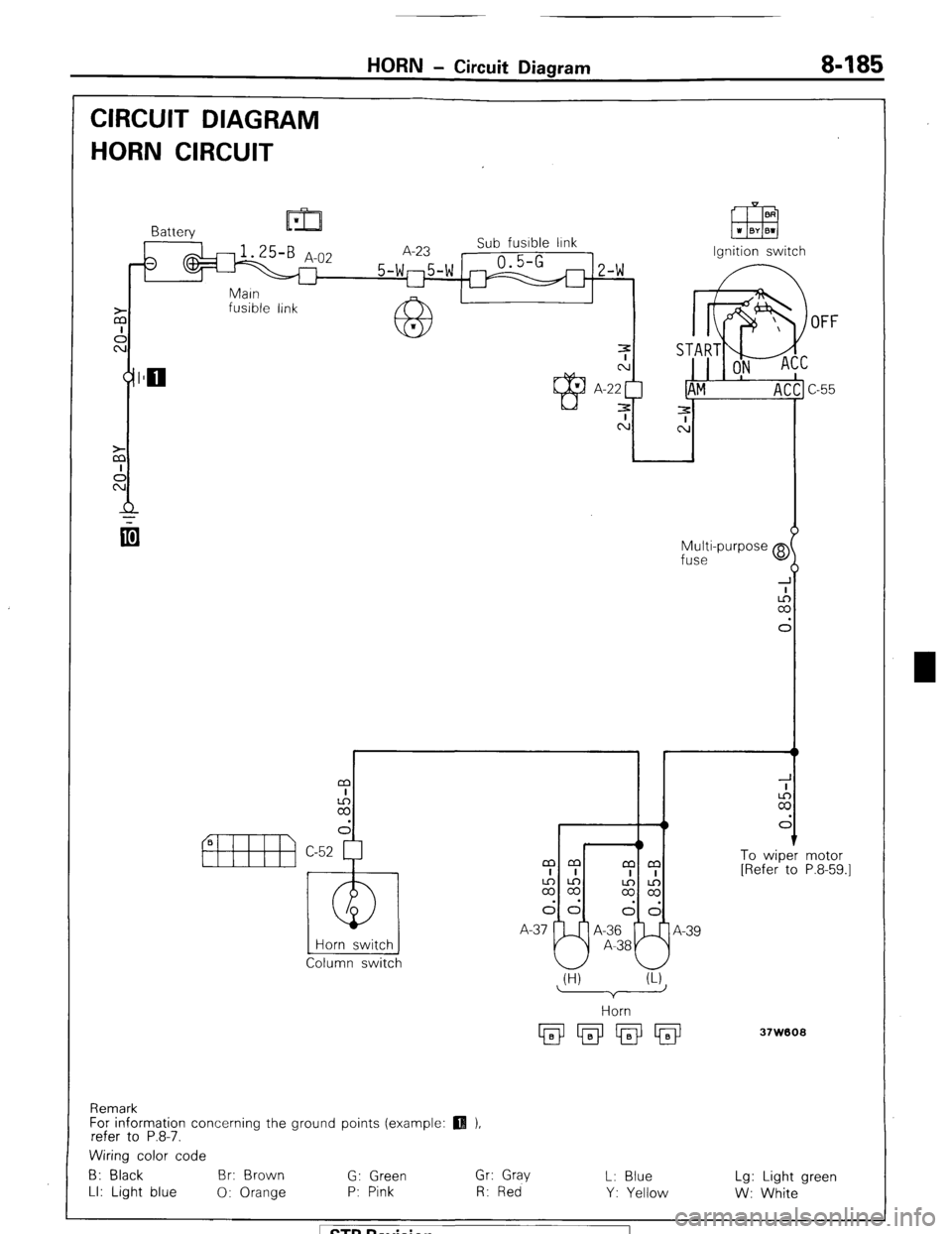
HORN - Circuit Diagram 8485
CIRCUIT DIAGRAM
HORN CIRCUIT
fusible link
OFF
Multi-purpose @
fuse
I r t
m
I
2
d
1 To wiper
[Refer to
Horn switch
Column switch mm
mm
I I
I I
2%
$2
dd
I--J!
dd
A-37 A-36
A-39
A-38 motor
P.8-59.1
(H) (U
37W608
Remark
For information concerning the ground points (example:
refer to P.8-7.
Wiring color code
B: Black Br: Brown
G: Green Gr: Gray
L: Blue Lg: Light green
LI: Light blue
0: Orange P: Pink R: Red
Y: Yellow
W: White 1 STB Revision
Page 209 of 284
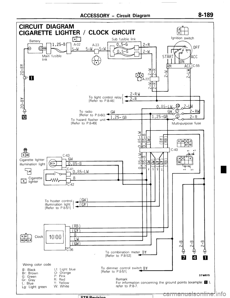
ACCESSORY - Circuit Diagram 8-189
CIRCUIT DIAGRAM
LW
CIGARETTE LIGHTER / CLOCK CIRCUIT EB w
Sub fusible link
,-fs q M 15-W 5-W 25-W m ;I;
I I
-
Main fusible -
link Ignition switch
3e
I I
NN
,
Z-RW To
linht cnntrnl r&v I 4 0 n
I 1 - .J . __._ - -., [Refer to P.8-461
I 4 L-K A
To radio
GW [Refer to P.8-601 + 1 .25- GB
To hazard flasher unit4
[Refer to P.8-491
Multi-purpose fuse
illumination light
’ To heater control
illumination light
[Refer to P 8-511
r
i I
To combination meter BY
Wiring color code
B: Black LI: Light blue
Br: Brown 0: Orange
G: Green P: Pink
Gr: Gray R: Red
L: Blue Y: Yellow
Lg: Light green W: White
I
I - - m
I
N
Q
-
[Refer to P.8-521 -
To dimmer control switch BY
[Refer to P 8-511 .I
Remark 37W615
For information concerning the ground points (example: 0 ).
refer to P.8-7.
1 STB Revision