air filter MITSUBISHI MONTERO 1987 1.G Workshop Manual
[x] Cancel search | Manufacturer: MITSUBISHI, Model Year: 1987, Model line: MONTERO, Model: MITSUBISHI MONTERO 1987 1.GPages: 284, PDF Size: 14.74 MB
Page 113 of 284
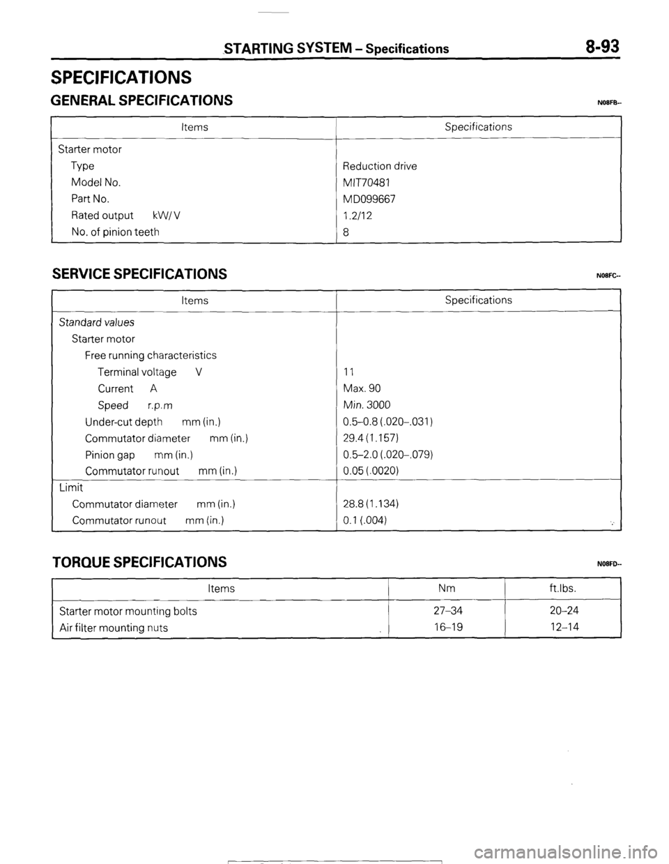
SPECIFICATIONS
STARTING SYSTEM - Specifications 8-93
GENERAL SPECIFICATIONS NOIFB-
Items
Starter motor
Type
Model No.
Part No.
Rated output kW1 v
No. of pinion teeth Specifications
Reduction drive
MIT70481
M DO99667
I.2112
8
SERVICE SPECIFICATIONS
Items
Standard values
Starter motor
Free running characteristics
Terminal voltage V
Current A
Speed r.p.m
Under-cut depth mm (in.)
Commutator diameter mm (in.)
Pinion gap mm (in.)
Commutator runout mm (in.)
Limit
Commutator diameter mm (in.)
Commutator runout mm (in.) Specifications
11
Max. 90
Min. 3000
0.5-0.8(.020-,031)
29.4(1.157)
0.5-2.0(.020-,079)
0.05(.0020)
28.8(1.134)
0.1 (.004)
'_'
TORQUE SPECIFICATIONS
Items Nm ftlbs.
Starter motor mounting bolts 27-34 20-24
Air filter mounting nuts 16-19
12-14
1 STB Revision
Page 117 of 284
STARTING WSTEM - Starter Motor 8-97
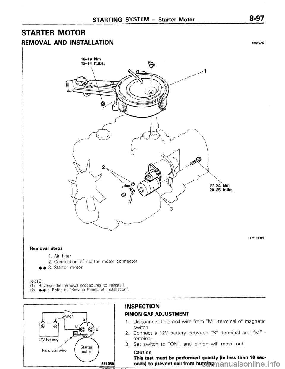
STARTER MOTOR
REMOVAL AND INSTALLATION NOBFJAE
16-19 Nm 16-19 Nm
12-l? ft.lbs. 12-14 ft.lbs.
15W1564
Removal steps
1. Air filter
2. Connection of starter motor connector
l * 3. Starter motor
NOTE
(1) Reverse the removal procedures to reinstall.
(2) ++ : Refer to “Service Points of Installation”
6EL05( This test must be performed quickly (in less than 10 sec-
onds) to prevent coil from burning. D Revision
INSPECTION PINION GAP ADJUSTMENT
I, Disconnect field coil wire from “M” -terminal of magnetic
switch.
2. Connect a 12V battery between “S” -terminal and “M” -
terminal.
3. Set switch to “ON”, and pinion will move out.
Caution
Page 244 of 284
24-8 HEATERS - Service Adjustment Procedures
ater valve cover
2OW751
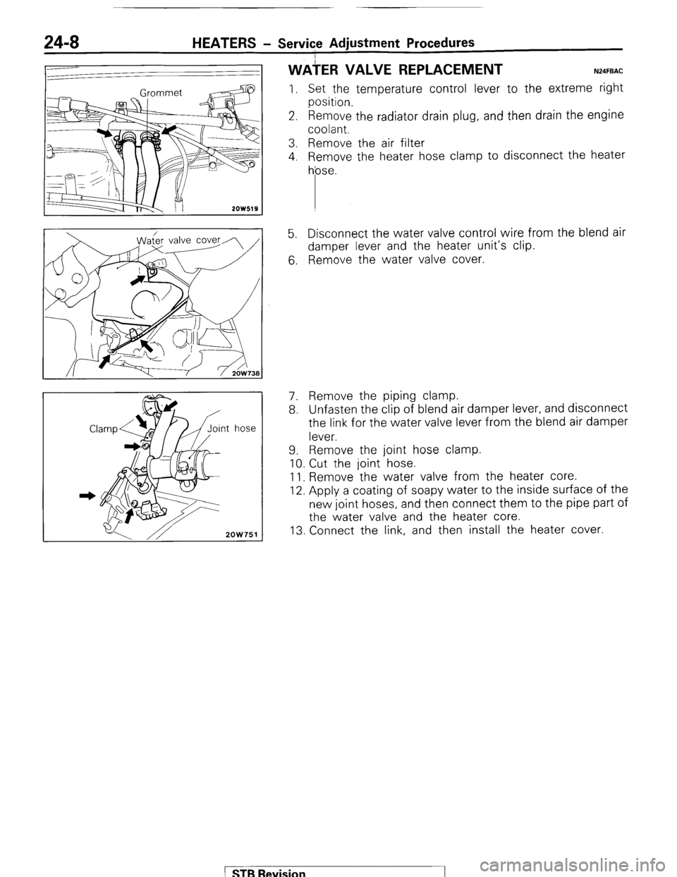
WAiER VALVE REPLACEMENT N24FBAC
I. Set the temperature control lever to the extreme right
position.
2. Remove the radiator drain plug, and then drain the engine
coolant.
3. Remove the air filter
4. Remove the heater hose clamp to disconnect the heater
hose.
5. Disconnect the water valve control wire from the blend air
damper lever and the heater unit’s clip.
6. Remove the water valve cover.
7. Remove the piping clamp.
8. Unfasten the clip of blend air damper lever, and disconnect
the link for the water valve lever from the blend air damper
lever.
9. Remove the joint hose clamp.
10. Cut the joint hose.
11. Remove the water valve from the heater core.
12. Apply a coating of soapy water to the inside surface of the
new joint hoses, and then connect them to the pipe part of
the water valve and the heater core.
13. Connect the link, and then install the heater cover.
1 STB Revision
Page 248 of 284
24-12 HEATERS - Heater Unit
I
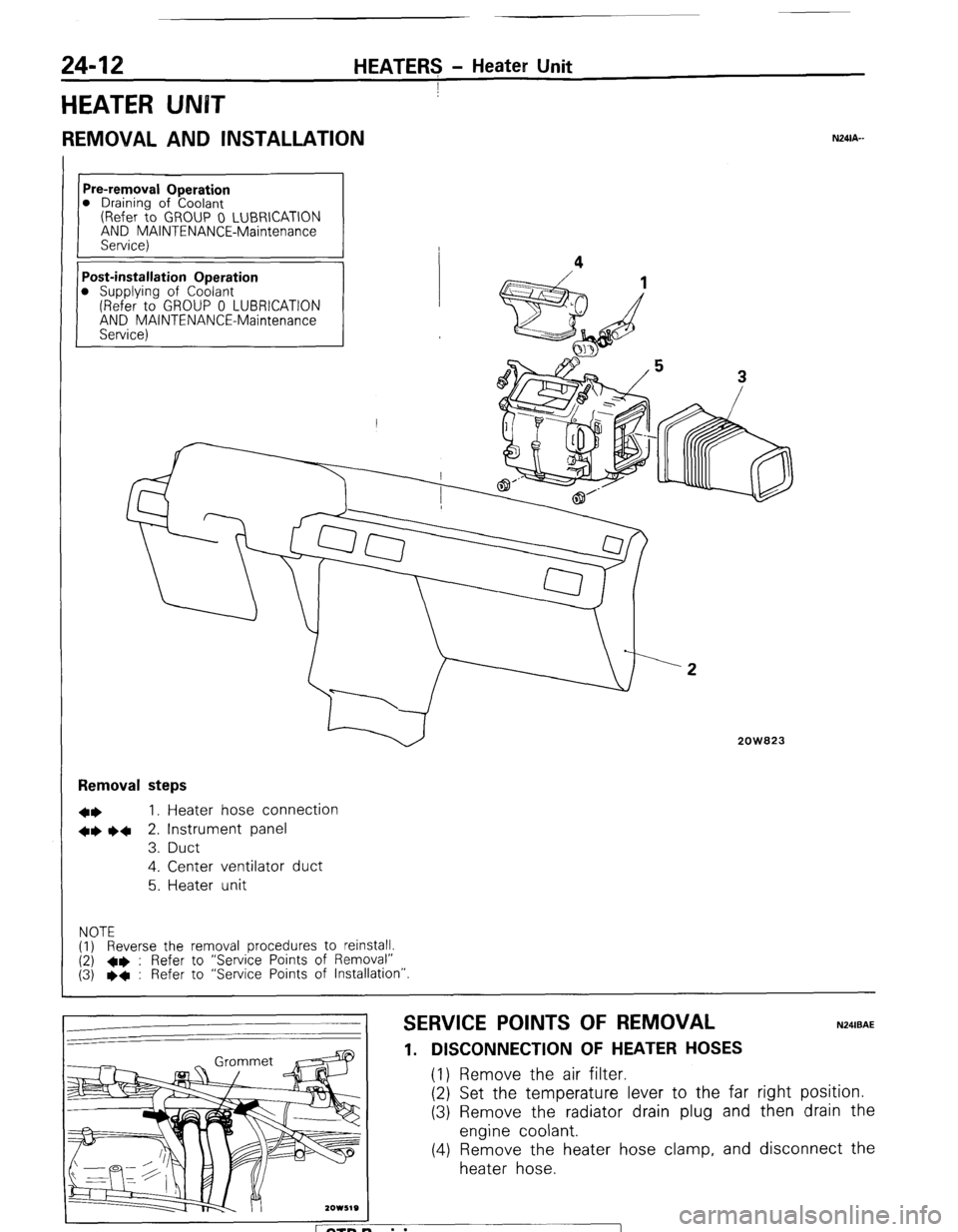
HEATER UNBT
REMOVAL AND INSTALLATION
Pre-removal Operation
0 Draining of Coolant
(Refer to GROUP 0 LUBRICATION
AND MAINTENANCE-Maintenance
Service)
Post-installation Operation
0 Supplying of Coolant
(Refer to GROUP 0 LUBRICATION
AND MAINTENANCE-Maintenance
Service) Removal steps
l *
I, Heater hose connection
+* l 4
2. Instrument panel
3. Duct
4. Center ventilator duct
5. Heater unit
NOTE
(1) Reverse the removal procedures to reinstall.
(2) +e : Refer to “Service Points of Removal”
(3) l
+ : Refer to “Service Points of Installation”
2OW823
SERVICE POINTS OF REMOVAL
1. DISCONNECTION OF HEATER HOSES (1) Remove the air filter.
(2) Set the temperature lever to the far
(3) Remove the radiator drain plug and
engine coolant.
(4) Remove the heater hose clamp, and
heater hose.
N24lBAE right position.
then drain the
disconnect the
ETB Revision
Page 270 of 284
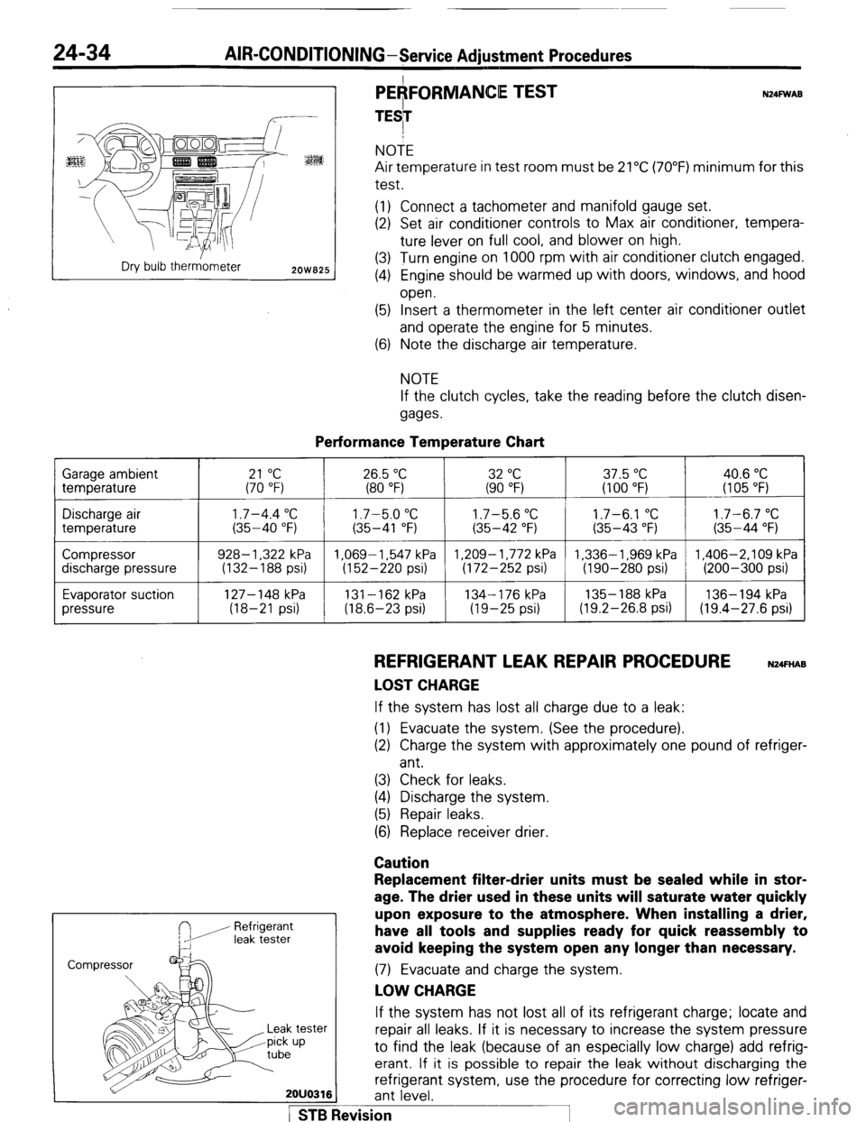
24-34 AIR-CONDITIONING-Service Adiustment Procedures
r---- :
:ES
Dry bulb therr&neter
2OW825
PEAFORMANCE TEST
TESI N24FWAB NOTE
Air temperature in test room must be 21°C (70°F) minimum for this
test.
(1) Connect a tachometer and manifold gauge set.
(2) Set air conditioner controls to Max air conditioner, tempera-
ture lever on full cool, and blower on high.
(3) Turn engine on 1000 rpm with air conditioner clutch engaged.
(4) Engine should be warmed up with doors, windows, and hood
open.
(5) Insert a thermometer in the left center air conditioner outlet
and operate the engine for 5 minutes.
(6) Note the discharge air temperature.
NOTE
If the clutch cycles, take the reading before the clutch disen-
gages.
Performance Temperature Chart Garage ambient
temperature
21 “C 26.5 “C 32 “C 37.5 “C 40.6 “C (70 “F) (80 “F) (90 “F) (100 “F) (I 05 “F)
Discharge air
temperature
Compressor
discharge pressure
Evaporator suction
pressure
1.7-4.4 “C 1.7-5.0 “C 1.7-5.6 “C 1.7-6.1 “C 1.7-6.7 “C (35-40 “F) (35-41 “F) (35-42 “F) (35-43 “F) (35-44 “F)
928- 1,322 kPa 1.069-1.547 kPa 1,209-1,772 kPa 1,336-1,969 kPa 1,406-2,109 kPa
(132-188 psi) (152-220 psi) (172-252 psi) (190-280 psi) (200-300 psi)
127-148 kPa
131-162 kPa 134-176 kPa 135- 188 kPa 136-194 kPa
(18-21 psi) (18.6-23 psi) (19-25 psi) (19.2-26.8 psi) (19.4-27.6 psi)
REFRIGERANT LEAK REPAIR PROCEDURE N24FnAB
LOST CHARGE If the system has lost all charge due to a leak:
(1) Evacuate the system. (See the procedure).
(2) Charge the system with approximately one pound of refriger-
ant.
(3) Check for leaks.
(4) Discharge the system.
(5) Repair leaks.
(6) Replace receiver drier.
Caution
Refrigerant
leak tester
Replacement filter-drier units must be sealed while in stor-
age. The drier used in these units will saturate water quickly
upon exposure to the atmosphere. When installing a drier,
have all tools and supplies ready for quick reassembly to
avoid keeping the system open any longer than necessary. (7) Evacuate and charge the system.
LOW CHARGE If the system has not lost all of its refrigerant charge; locate and
tester repair all leaks. If it is necessary to increase the system pressure
up to find the leak (because of an especially low charge) add refrig-
erant. If it is possible to repair the leak without discharging the
refrigerant system, use the procedure for correcting low refriger-
2OUO316 ant level.
1 STB Revision