width MITSUBISHI MONTERO 1987 1.G Workshop Manual
[x] Cancel search | Manufacturer: MITSUBISHI, Model Year: 1987, Model line: MONTERO, Model: MITSUBISHI MONTERO 1987 1.GPages: 284, PDF Size: 14.74 MB
Page 17 of 284

INTRODUCTION - Geraeral Data and Specifications 17
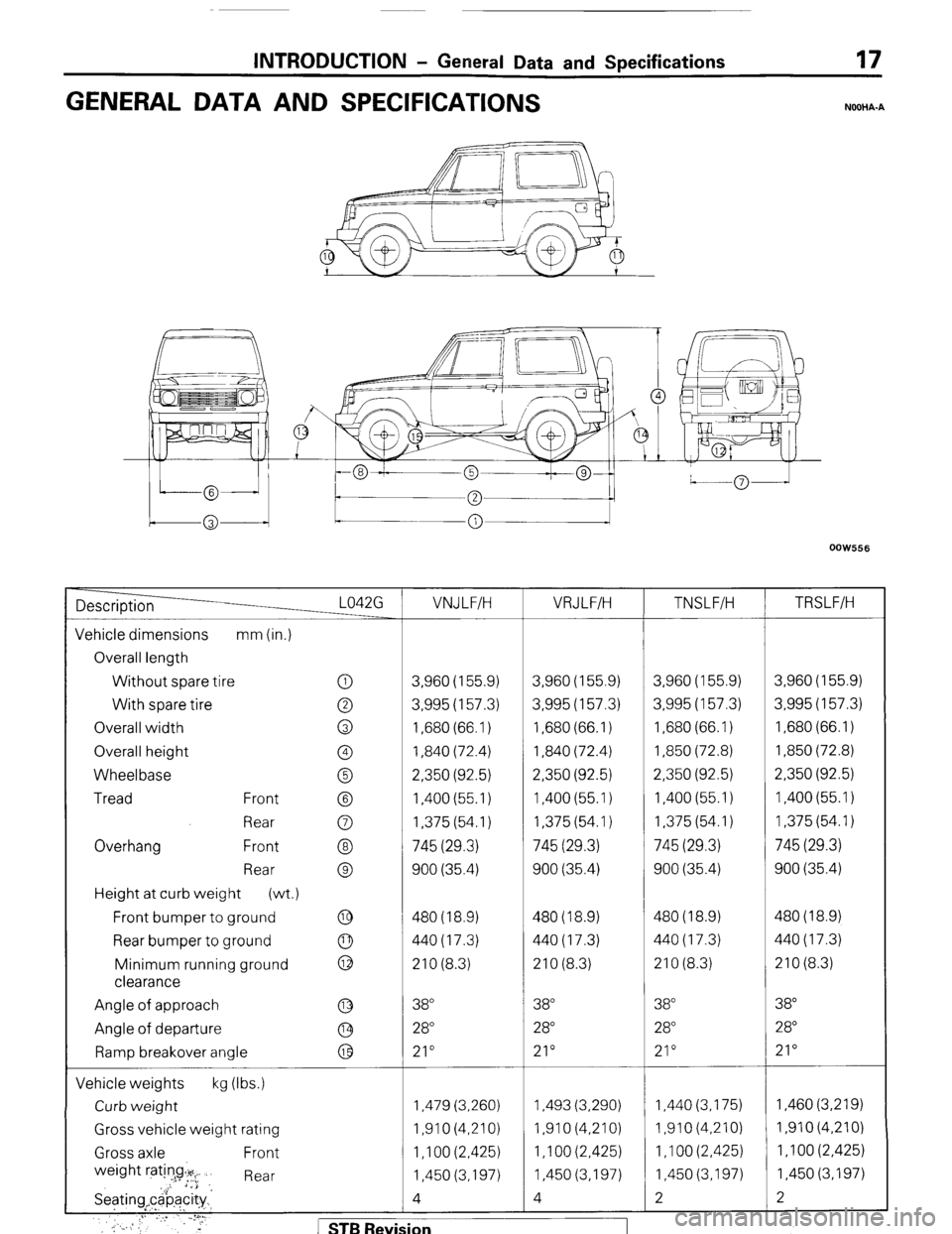
GENERAL DATA AND SPECIFICATIONS
NOOHA-A
OOW556
Description L042G VNJ LFIH VRJLFIH
TNSLFIH TRSLF/H
Vehicle dimensions mm (in.)
Overall length
Without tire
spare 0 3,960 (155.9) 3,960 (155.9) 3,960 (155.9) 3,960 (155.9)
With tire spare 0 3,995 (157.3) 3,995 (157.3) 3,995 (157.3) 3,995 (157.3)
Overall width 0 1,680 (66.1) 1,680 (66.1) 1,680 (66.1) 1,680 (66.1)
Overall height 0 1,840 (72.4) 1,840 (72.4) 1,850 (72.8) 1,850 (72.8)
Wheelbase 0 2,350 (92.5) 2,350 (92.5) 2,350 (92.5) 2,350 (92.5)
Tread Front @ 1,400 (55.1) 1,400 (55.1) 1,400 (55.1) 1,400 (55.1)
Rear 0 1,375 (54.1) 1,375 (54.1) 1,375 (54.1) 1,375 (54.1)
Overhang Front @ 745 (29.3) 745 (29.3) 745 (29.3) 745 (29.3)
Rear @ 900 (35.4) 900 (35.4) 900 (35.4) 900 (35.4)
Height at curb weight
(wt.)
Front bumper to ground
@ 480 (18.9) 480 (18.9) 480(18.9) 480 (18.9)
Rear bumper to ground 440(17.3) 440(17.3) 440(17.3) 440(17.3)
Minimum running ground : 210 (8.3) 210 (8.3) 210 (8.3) 210 (8.3)
clearance
Angle of approach @ 38 38 38” 38
Angle of departure @ 28 28” 28 28
Ramp breakover angle
@ 21” 21” 21” 21”
Vehicle weights kg (Ibs.)
Curb weight 1,479 (3,260) 1,493 (3,290) 1,440 (3,175) 1,460 (3,219)
Gross vehicle weight rating 1,910 (4,210) I,91 0 (4,210) 1,910(4,210) I,91 0 (4.210)
Gross axle Front 1 ,I 00 (2,425) 1 ,I 00 (2,425) 1 ,I 00 (2,425) 1,100 (2,425)
weight ratin!g~:+y~ Rear 1,450 (3,197) 1,450 (3,197) 1,450 (3,197) 1,450 (3,197)
Seating,c&ac&~ 4 4 2 2
.’ .’ :I’ ;.,* ..,, VU.,
,: ‘,_. : ., ”
,_;. ,; ,: 3,‘. r STB Revision
Page 29 of 284

INSPECTION OF HARNESS CONNECTOR - Inspection of Harness Connector 8-9
Connect to
harness
16UO500
16R1317
8; 4 16R1319
INSPECTION OF HARNESS
CONNECTOR
NOECAM
CONTINUITY AND VOLTAGE TEST FOR CONNEC-
TOR
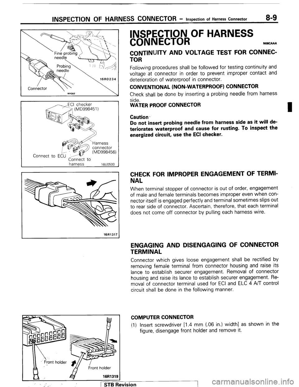
Following procedures shall be followed for testing continuity and
voltage at connector in order to prevent improper contact and
deterioration of waterproof in connector.
CONVENTIONAL (NON-WATERPROOF) CONNECTOR
Check shall be done by inserting a probing needle from harness
side.
WATER PROOF CONNECTOR
Caution.
Do not insert probing needle from harness side as it will de-
teriorates waterproof and cause for rusting. To inspect the
energized circuit, use the ECI checker.
CHECK FOR IMPROPER ENGAGEMENT OF TERMI-
NAL
When terminal stopper of connector is out of order, engagement
of male and female terminals becomes improper even when con-
nector itself is engaged perfectly and terminal sometimes slips out
to rear side of connector. Ascertain, therefore, that each terminal
does not come off connector by pulling each harness wire.
ENGAGING AND DISENGAGING OF CONNECTOR
TERMINAL
Connector which gives loose engagement shall be rectified by
removing female terminal from connector housing and raise its
lance to establish securer engagement. Removal of connector
housing and raise its lance to establish securer engagement. Re-
moval of connector terminal used for ECI and ELC 4 ,4/l control
circuit shall be done in the following manner.
COMPUTER CONNECTOR
(1) Insert screwdriver [1.4 mm (06 in.) width] as shown in the
figure, disengage front holder and remove it.
:
j ’ . _. 1 STB Revision
Page 30 of 284

8-10 INSPECTION OF HARNESS CONNECTOR - Inspection of Harness Connector
Housing lance
-5
1 16R1321
’ Needle
16Ffi322
Housing lance
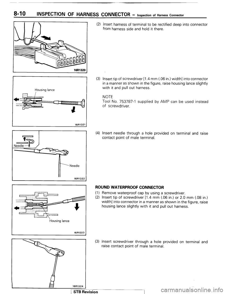
16R1323 (2) Insert harness of terminal to be rectified deep into connector
from harness side and hold it there.
(3) Insert tip of screwdriver [1.4 mm (.06 in.) width] into connector
in a manner as shown in the figure, raise housing lance slightly
with it and pull out harness.
NOTE
Tool No. 753787-l supplied by AMP can be used instead
of screwdriver.
(4) Insert needle through a hole provided on terminal and raise
contact point of male terminal.
ROUND WATERPROOF CONNECTOR (1) Remove waterproof cap by using a screwdriver.
(2) Insert tip of screwdriver [1.4 mm (.06 in.) or 2.0 mm (.08 in.)
width] into connector in a manner as shown in the figure, raise
housing lance slightly with it and pull out harness.
(3) Insert screwdriver through a hole provided on terminal and
raise contact point of male terminal.
Page 31 of 284

INSPECTION OF HARNESS CONNECTOR - Inspection of Harness Connector 8-71
RECTANGULAR WATERPROOF CONNECTOR
(1) Disengage front holder by using a screwdriver and remove it.
(2) Insert tip of screwdriver [*0.8 mm (03 in.) width] into connec-
tor in a manner as shown in the figure, push it lightly to raise
housing lancer and pull out harness.
*If right size screwdriver is not available, convert a conven-
tional driver to suit the size.
Housing lance
16R13 26
16R1329
L 16R1326)
(2)
Terminal lance
16Rl330
1 STB Revision (3) Press contact point of male terminal down by holding a screw-
driver [1.4 mm (.06 in.) width] in a manner as shown in the
figure.
INJECTOR CONNECTOR
(1) Remove waterproof cap.
Insert tip of screwdriver [1.4
in a manner as shown in the
pull out harness. mm (06 in.) width] into connector
figure, press in terminal lance and
Page 32 of 284
![MITSUBISHI MONTERO 1987 1.G Workshop Manual 8-12 INSPECTION OF HARNESS CONNECTOR - Inspection of Harness Connector
16R132i
(3) Press contact point of male terminal down by holding a screw-
driver Il.4 mm (.06 in.) width] in a manner as shown MITSUBISHI MONTERO 1987 1.G Workshop Manual 8-12 INSPECTION OF HARNESS CONNECTOR - Inspection of Harness Connector
16R132i
(3) Press contact point of male terminal down by holding a screw-
driver Il.4 mm (.06 in.) width] in a manner as shown](/img/19/7559/w960_7559-31.png)
8-12 INSPECTION OF HARNESS CONNECTOR - Inspection of Harness Connector
16R132i
(3) Press contact point of male terminal down by holding a screw-
driver Il.4 mm (.06 in.) width] in a manner as shown in the
figure.
Caution
Correct lancer to be in proper condition before terminal is
inserted into connector.
I
1 STB Revision