change wheel MITSUBISHI MONTERO 1987 1.G Workshop Manual
[x] Cancel search | Manufacturer: MITSUBISHI, Model Year: 1987, Model line: MONTERO, Model: MITSUBISHI MONTERO 1987 1.GPages: 284, PDF Size: 14.74 MB
Page 1 of 284

Service Manual
MONTERO
1987 : Volume 2
FOREWORD
This Service Manual has been prepared with the
latest service information available at the time of
publication. It is subdivided into various group
categories and each section contains diagnosis,
disassembly, repair, and installation procedures
along with complete specifications and tightening
references. Use of this manual will aid in properly
performing any servicing necessary to maintain or
restore the high levels of performance and reliability
designed into these outstanding vehicles.
WE SUPPORT
VOLUNTARY TECHNICIAN
CERTIFICATION THROUGH
MITSUBISHI MOTOR SALES OF AMERICA. Inc.
Mitsubishi Motors corporation reserves the right to make changes in
design or to make additions to or improvements in its products without
imposing any obligations upon itself to install them on its products
previously manufactured.
I
GROUP/SECTION INDEX ‘kme-.
INTRODUCTION ..............................
Electrical ...........................................
Electrical System Parts
Location .........................................
Relays, Control Units, Sensors,
Fuses, Groundings
Inspection of Harness
Connector ......................................
Wiring Harness .............................
Charging System ..........................
Starting System ............................
Ignition System .............................
Meters and Gauges ......................
Lighting System .............................
Wiper and Washer System ..........
Horn ...............................................
Accessory ......................................
Audio System ................................
Back Door Window Defogger ......
Automatic Free-wheeling Hub
Indicator System ..........................
Heaters and Air-conditioning .........
Heaters ..........................................
Air-conditioning ............................
**, For Engine Chassis & Body refer to
0 1986 Mitsubishi Motors Corporation Printed in Japan
Page 229 of 284

AUTOMATIC FREE-WHEELING HUB INDICATOR SYSTEM - General Information 8-209
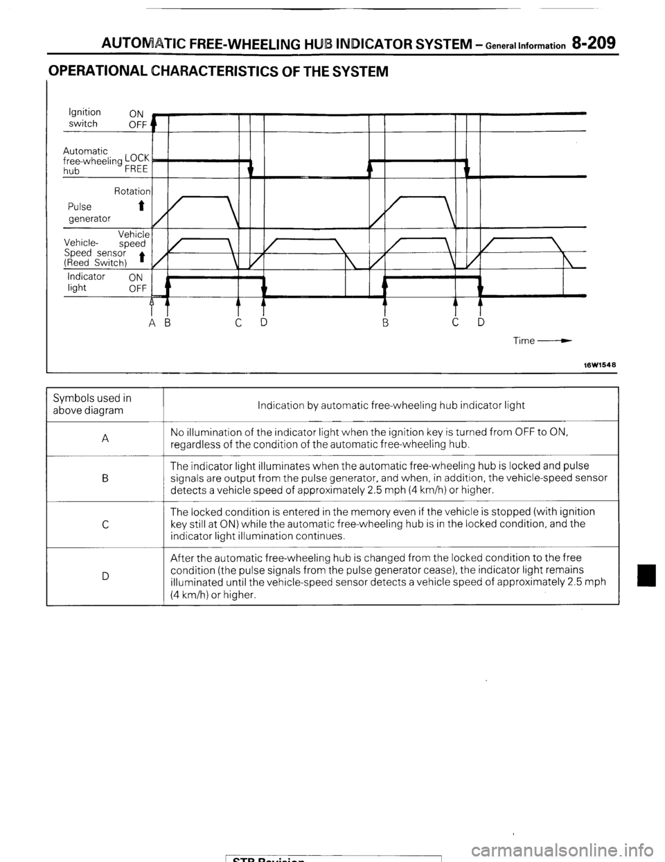
OPERATIONAL CHARACTERISTICS OF THE SYSTEM
Time-----w
16W1548 Indication by automatic free-wheeling hub indicator light
No illumination of the indicator light when the ignition key is turned from OFF to ON,
regardless of the condition of the automatic free-wheeling hub.
The indicator light illuminates when the automatic free-wheeling hub is locked and pulse
signals are output from the pulse generator, and when, in addition, the vehicle-speed sensor
detects a vehicle speed of approximately 2.5 mph (4 km/h) or higher.
The locked condition is entered in the memory even if the vehicle is stopped (with ignition
key still at ON) while the automatic free-wheeling hub is in the locked condition, and the
indicator light illumination continues.
After the automatic free-wheeling hub is changed from the locked condition to the free
condition (the pulse signals from the pulse generator cease), the indicator light remains
illuminated until the vehicle-speed sensor detects a vehicle speed of approximately 2.5 mph
(4 km/h) or higher. Symbols used in
above diagram
A
B
C
D
1 STB Revision
Page 231 of 284

AUTOMATIC FREE-WHEELING HUB INDICATOR SYSTEM - Generallnformation 8-211
3. Automatic free-wheeling hub in free condition
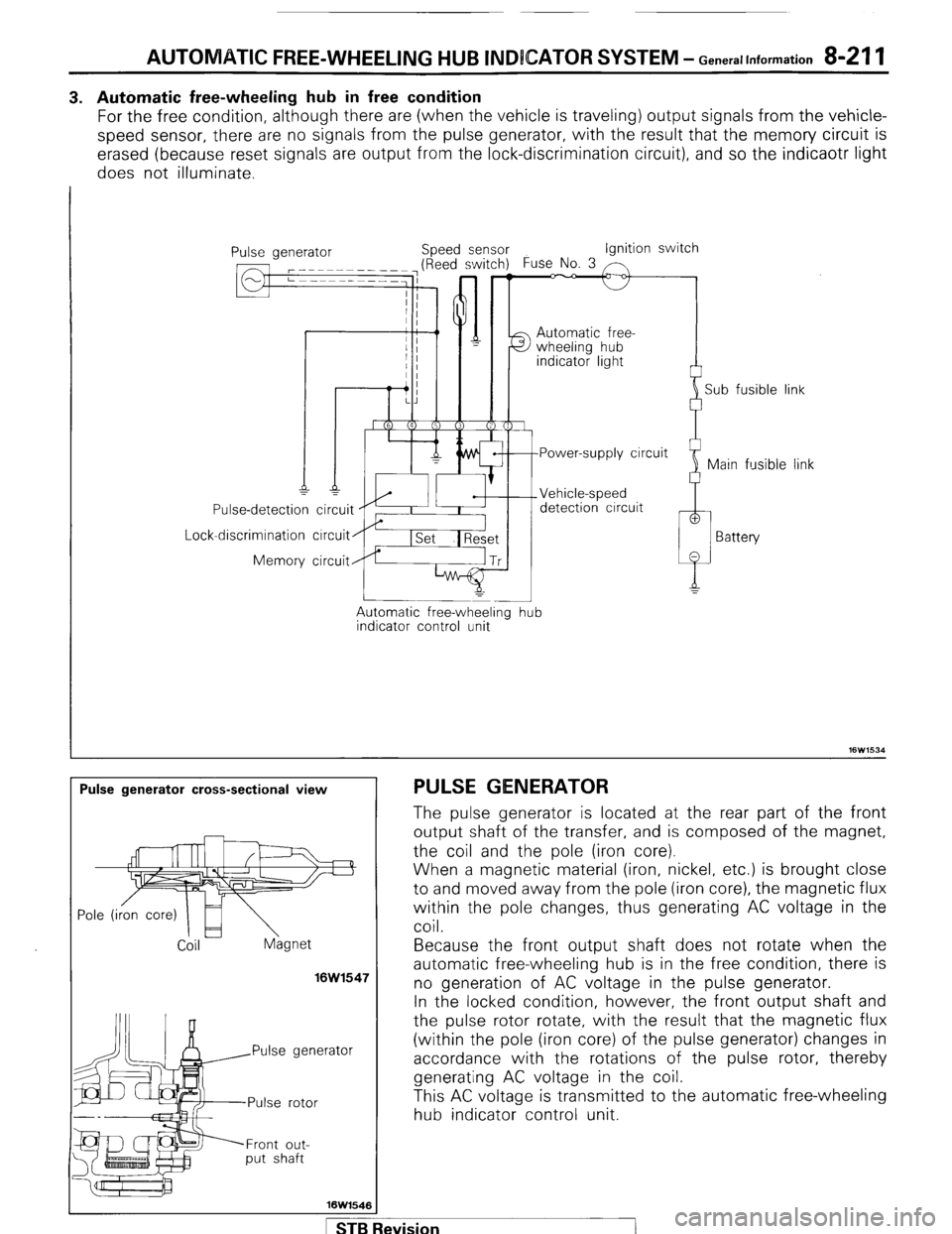
For the free condition, although there are (when the vehicle is traveling) output signals from the vehicle-
speed sensor, there are no signals from the pulse generator, with the result that the memory circuit is
erased (because reset signals are output from the lock-discrimination circuit), and so the indicaotr light
does not illuminate.
I
Lock Use-detection
-discrimination
Memory ipeed sensor Ignition switch
Automatic free-
detection circuit
circuit
circuit
Automatic free-wheeling
indicator control unit -
hub i
Sub fusible link
link
Pulse generator cross-sectional view PULSE GENERATOR
Coil hgnet
16W1547
rator
Front out-
put shaft
16W1546 The pulse generator is located at the rear part of the front
output shaft of the transfer, and is composed of the magnet,
the coil and the pole (iron core).
When a magnetic material (iron, nickel, etc.) is brought close
to and moved away from the pole (iron core), the magnetic flux
within the pole changes, thus generating AC voltage in the
coil.
Because the front output shaft does not rotate when the
automatic free-wheeling hub is in the free condition, there is
no generation of AC voltage in the pulse generator.
In the locked condition, however, the front output shaft and
the pulse rotor rotate, with the result that the magnetic flux
(within the p o e I (’ Iron core) of the pulse generator) changes in
accordance with the rotations of the pulse rotor, thereby
generating AC voltage in the coil.
This AC voltage is transmitted to the automatic free-wheeling
hub indicator control unit.
STB Revision
Page 233 of 284

AUTOMATIC FREE-WHEELING HUB INDICATOR SYSTEM -Troubleshooting 8-213
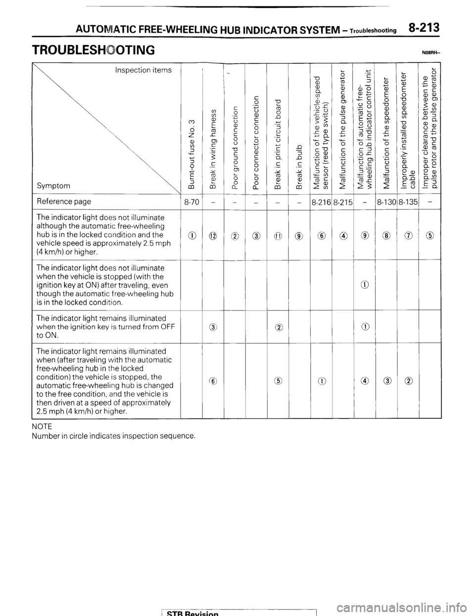
TROUBLESHOOTING NOIRH-
Inspection items
Symptom
Reference page
3-21E
0 The indicator light does not illuminate
although the automatic free-wheeling
hub is in the locked condition and the
vehicle speed is approximately 2.5 mph
(4 km/h) or higher.
0 0 0
0
The indicator light does not illuminate
when the vehicle is stopped (with the
ignition key at ON) after traveling, even
though the automatic free-wheeling hub
is in the locked condition.
The indicator light remains illuminated
when the ignition key is turned from OFF
to ON.
0
0 0 0
a 0
The indicator light remains illuminated
when (after traveling with the automatic
free-wheeling hub in the locked
condition) the vehicle is stopped, the
automatic free-wheeling hub is changed
to the free condition, and the vehicle is
then driven at a speed of approximately
2.5 mph (4 km/h) or higher.
0 Cc 0
NOTE
Number in circle indicates inspection sequence.
/ STB Revision