check engine light MITSUBISHI MONTERO 1987 1.G Workshop Manual
[x] Cancel search | Manufacturer: MITSUBISHI, Model Year: 1987, Model line: MONTERO, Model: MITSUBISHI MONTERO 1987 1.GPages: 284, PDF Size: 14.74 MB
Page 38 of 284
WIRING HARNESS - Troubleshooting
1660236
Power
supply
h
Fuse
ON
/----
/
/
Motor
1660239
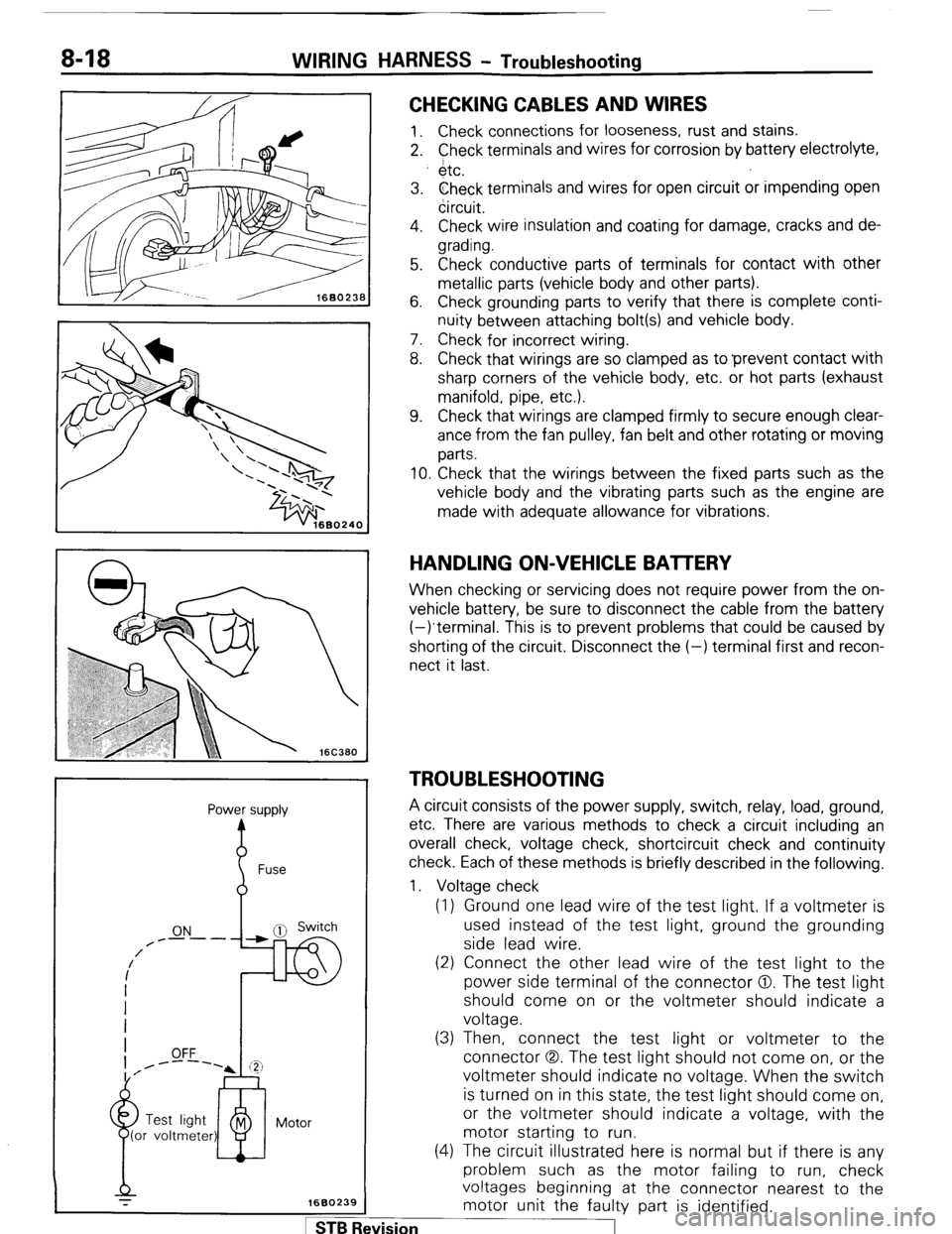
CHECKING CABLES AND WIRES
1. Check connections for looseness, rust and stains.
2. Check terminals and wires for corrosion by battery electrolyte,
$tc.
3. Check terminals and wires for open circuit or impending open
circuit.
4. Check wire insulation and coating for damage, cracks and de-
grading.
5. Check conductive parts of terminals for contact with other
metallic parts (vehicle body and other parts).
6. Check grounding parts to verify that there is complete conti-
nuity between attaching bolt(s) and vehicle body.
7. Check for incorrect wiring.
8. Check that wirings are so clamped as to ‘prevent contact with
sharp corners of the vehicle body, etc. or hot parts (exhaust
manifold, pipe, etc.).
9. Check that wirings are clamped firmly to secure enough clear-
ance from the fan pulley, fan belt and other rotating or moving
parts.
10. Check that the wirings between the fixed parts such as the
vehicle body and the vibrating parts such as the engine are
made with adequate allowance for vibrations.
HANDLING ON-VEHICLE BAlTERY
When checking or servicing does not require power from the on-
vehicle battery, be sure to disconnect the cable from the battery
(-)terminal. This is to prevent problems that could be caused by
shorting of the circuit. Disconnect the (-) terminal first and recon-
nect it last.
TROUBLESHOOTING
A circuit consists of the power supply, switch, relay, load, ground,
etc. There are various methods to check a circuit including an
overall check, voltage check, shortcircuit check and continuity
check. Each of these methods is briefly described in the following.
1. Voltage check
(1) Ground one lead wire of the test light. If a voltmeter is
used instead of the test light, ground the grounding
side lead wire.
(2) Connect the other lead wire of the test light to the
power side terminal of the connector 0. The test light
should come on or the voltmeter should indicate a
voltage.
(3) Then, connect the test light or voltmeter to the
connector (3,. The test light should not come on, or the
voltmeter should indicate no voltage. When the switch
is turned on in this state, the test light should come on,
or the voltmeter should indicate a voltage, with the
motor starting to run.
(4) The circuit illustrated here is normal but if there is any
problem such as the motor failing to run, check
voltages beginning at the connector nearest to the
motor unit the faulty part is identified. 1 ST6 Revision
Page 48 of 284
8-28 WIRING HARNESS - Engine Compartment
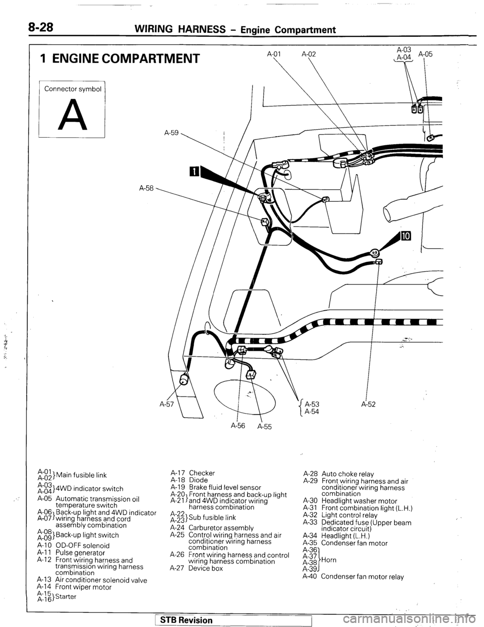
1 ENGINE COMPARTMENT
Connector symbol
A
;:::I Main fusible link
;:::I 4WD indicator switch
A-05 Automatic transmission oil
temperature switch
A-06 Back-u light and 4WD indicator
A-07)wiring f!arness and cord
assembly combination
;:g> Back-up light switch
A-l 0 OD-OFF solenoid
A-l 1 Pulse generator
A-l 2 Front wiring harness and
transmission wiring harness
combination
A-13 Air conditioner solenoid valve
A-l 4 Front wiper motor A-
A156
A-55
A-l 7 Checker
A-18 Diode
A-19 Brake fluid level sensor
A-20 Front harness and back-up light
A-21 land 4WD indicator wiring
harness combination
it;;> Sub fusible link
A-24 Carburetor assembly
A-25 Control wiring harness and air
conditioner wiring harness
combination
A-26 Front wiring harness and control
wiring harness combination
A-27 Device box A-53 A-52
A-54
A-28 Auto choke relay
A-29 Front wiring harness and air
conditioner wiring harness
combination
A-30 Headlight washer motor
A-31 Front combination light (L.H.)
A-32 Light control relay
A-33 Dedicated fuse (Upper beam
indicator circuit)
A-34 Headlight (L.H.)
A-35 Condenser fan motor
A-40 Condenser fan motor relay
1 STB Revision
Page 95 of 284
CHARGING SYSTEM -Troubleshooting 8-75
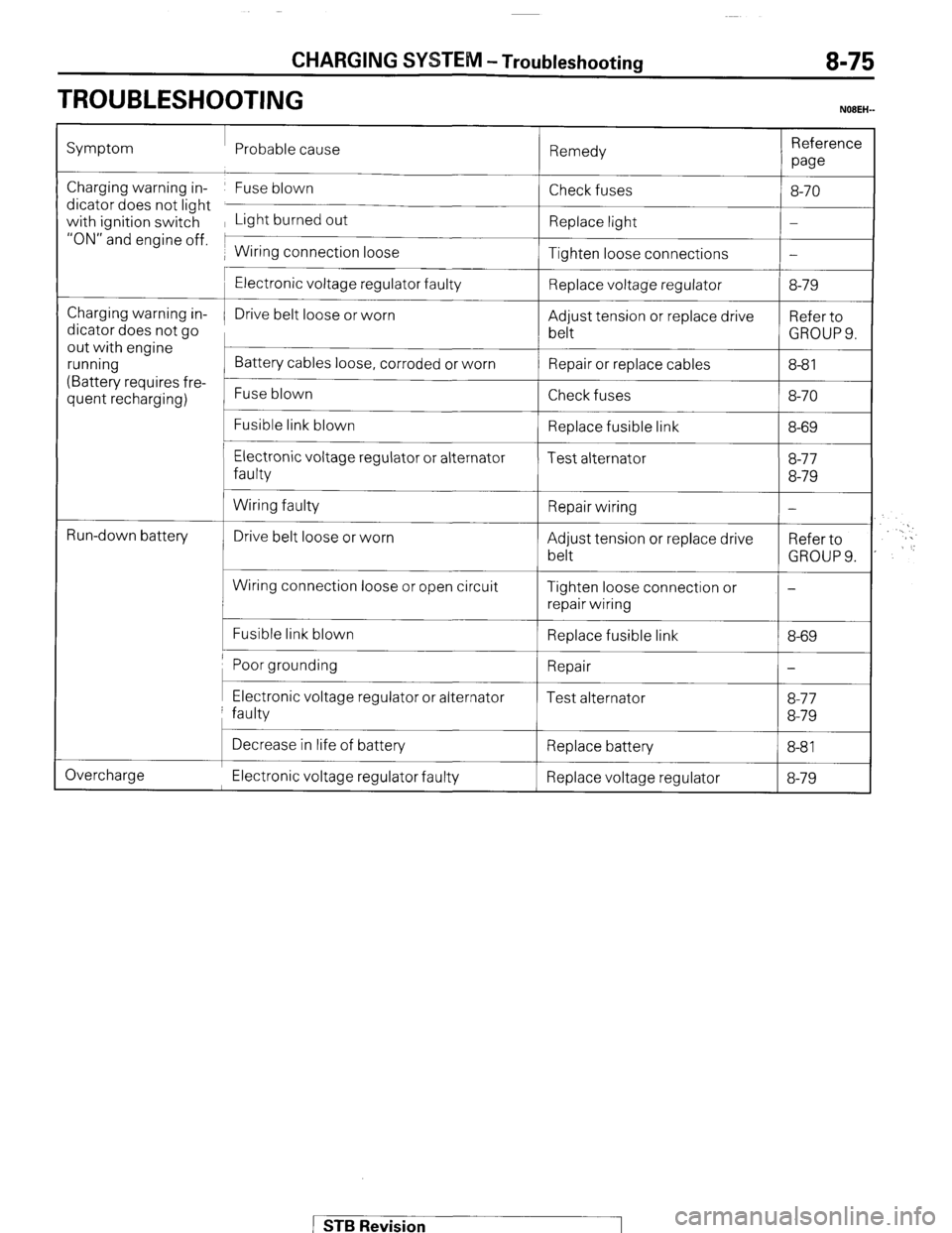
TROUBLESHOOTING
NOBEH-
Symptom Probable cause
Remedy Reference
we
Charging warning in- Fuse blown
dicator does not light
with ignition switch Light burned out
“ON” and engine off. 1
1 Wiring connection loose Check fuses
Replace light
Tighten loose connections 8-70
-
-
Charging warning in-
dicator does not go
out with engine
running
(Battery requires fre-
quent recharging)
L
t
Run-down battery
c
Electronic voltage regulator faulty
Drive belt loose or worn
Battery cables loose, corroded or worn
Fuse blown
Fusible link blown
Electronic voltage regulator or alternator
faulty
Wiring faulty
Drive belt loose or worn
Wiring connection loose or open circuit
Fusible link blown Replace voltage regulator
Adjust tension or replace drive
belt
Repair or replace cables
Check fuses
Replace fusible link
Test alternator
Repair wiring
Adjust tension or replace drive
belt
Tighten loose connection or
repair wiring
Replace fusible link 8-79
Refer to
GROUPS.
8-8 1
8-70
8-69
8-77
8-79
-
Refer to
GROUP 9.
-
8-69
Poor grounding 1 Repair
I-
I I I Electronic voltage regulator or alternator
faulty Test alternator 8-77
8-79
Overcharge Decrease in life of battery
Replace battery
8-81 I
Electronic voltage regulator faulty Replace voltage regulator 8-79
STB Revision
Page 97 of 284
CHARGING SYSTEM - Service Adjustment Procedures 8-77
SERVICE ADJUSTMENT PROCEDUREswmAB
lEL15I
INSPECTION OF THE CHARGING SYSTEM
VOLTAGE DROP TEST OF ALTERNATOR OUTPUT WIRE
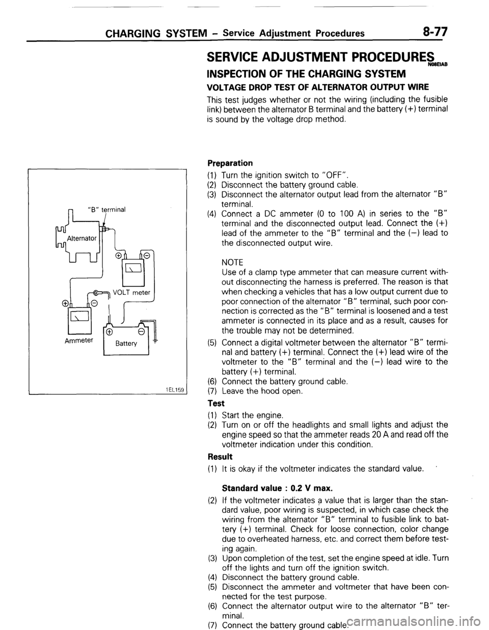
This test judges whether or not the wiring (including the fusible
link) between the alternator B terminal and the battery (+) terminal
is sound by the voltage drop method.
Preparation
(1) Turn the ignition switch to “OFF”.
(2) Disconnect the battery ground cable.
(3) Disconnect the alternator output lead from the alternator “B”
terminal.
(4) Connect a DC ammeter (0 to 100 A) in series to the “B”
terminal and the disconnected output lead. Connect the (+)
lead of the ammeter to the “B” terminal and the (-) lead to
the disconnected output wire.
NOTE
Use of a clamp type ammeter that can measure current with-
out disconnecting the harness is preferred. The reason is that
when checking a vehicles that has a low output current due to
poor connection of the alternator “B” terminal, such poor con-
nection is corrected as the “B” terminal is loosened and a test
ammeter is connected in its place and as a result, causes for
the trouble may not be determined.
(5) Connect a digital voltmeter between the alternator “B” termi-
nal and battery (+) terminal. Connect the (+) lead wire of the
voltmeter to the “B” terminal and the (-) lead wire to the
battery (+) terminal.
(6) Connect the battery ground cable.
(7) Leave the hood open.
Test
(1) Start the engine.
(2) Turn on or off the headlights and small lights and adjust the
engine speed so that the ammeter reads 20 A and read off the
voltmeter indication under this condition.
Result
(1) It is okay if the voltmeter indicates the standard value. ’
Standard value : 0.2 V max.
(2) If the voltmeter indicates a value that is larger than the stan-
dard value, poor wiring is suspected, in which case check the
wiring from the alternator “B” terminal to fusible link to bat-
tery (+) terminal. Check for loose connection, color change
due to overheated harness, etc. and correct them before test-
ing again.
(3) Upon completion of the test, set the engine speed at idle. Turn
off the lights and turn off the ignition switch.
(4) Disconnect the battery ground cable.
(5) Disconnect the ammeter and voltmeter that have been con-
nected for the test purpose.
(6) Connect the alternator output wire to the alternator “B” ter-
minal.
(7) Connect the battery ground cable.
( STB Revision
Page 98 of 284
8-78 CHARGING SYSTEM - Service Adiustment Procedures
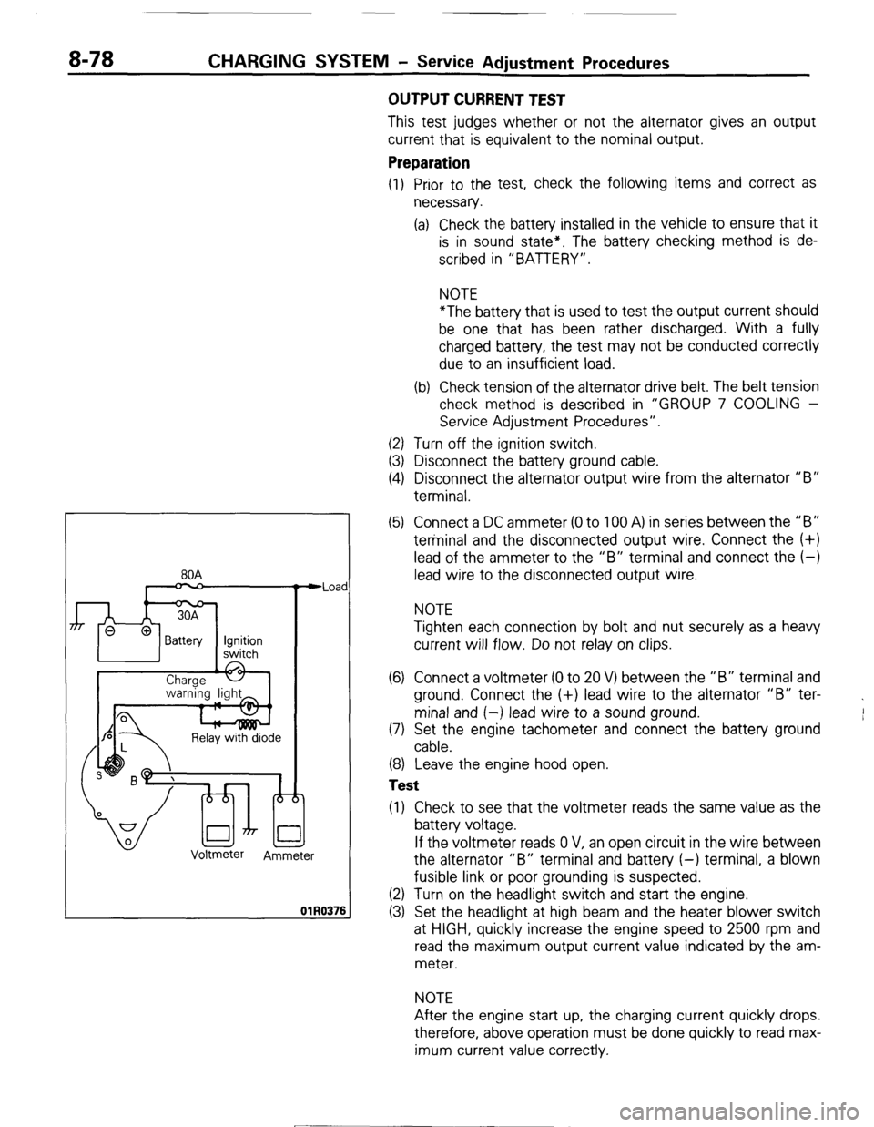
80A
n
Relay with diode
Voltmeter
Ammeter Iad
176
OUTPUT CURRENT TEST
This test judges whether or not the alternator gives an output
current that is equivalent to the nominal output.
Preparation
(1) Prior to the test, check the following items and correct as
necessary.
(a) Check the battery installed in the vehicle to ensure that it
is in sound state*. The battery checking method is de-
scribed in “BATTERY”.
NOTE
*The battery that is used to test the output current should
be one that has been rather discharged. With a fully
charged battery, the test may not be conducted correctly
due to an insufficient load.
(b) Check tension of the alternator drive belt. The belt tension
check method is described in “GROUP 7 COOLING -
Service Adjustment Procedures”.
(2) Turn off the ignition switch.
(3) Disconnect the battery ground cable.
(4) Disconnect the alternator output wire from the alternator “B”
terminal.
(5) Connect a DC ammeter (0 to 100 A) in series between the “B”
terminal and the disconnected output wire. Connect the (+)
lead of the ammeter to the “B” terminal and connect the (-)
lead wire to the disconnected output wire.
NOTE
Tighten each connection by bolt and nut securely as a heavy
current will flow. Do not relay on clips.
(6) Connect a voltmeter (0 to 20 V) between the “B” terminal and
ground. Connect the (+) lead wire to the alternator “B” ter-
minal and (-) lead wire to a sound ground.
(7) Set the engine tachometer and connect the battery ground
cable.
(8) Leave the engine hood open.
Test
(1) Check to see that the voltmeter reads the same value as the
battery voltage.
If the voltmeter reads 0 V, an open circuit in the wire between
the alternator “B” terminal and battery (-) terminal, a blown
fusible link or poor grounding is suspected.
(2) Turn on the headlight switch and start the engine.
(3) Set the headlight at high beam and the heater blower switch
at HIGH, quickly increase the engine speed to 2500 rpm and
read the maximum output current value indicated by the am-
meter.
NOTE
After the engine start up, the charging current quickly drops.
therefore, above operation must be done quickly to read max-
imum current value correctly.
[ STB Revision
--I
Page 99 of 284
CHARGING SYSTEM - Service Adjustment Procedures 8-79
Result
(1) The ammeter reading must be higher than the limit value. If it
is lower but the alternator output wire is normal, remove the
alternator from the vehicle and check it.
Limit value : 31 A min.
Caution
1. The nominal output current value is shown on the
nameplate affixed to the alternator body.
2. The output current value changes with the electrical
load and the temperature of the alternator itself.
Therefore, the nominal output current may not be ob-
tained if the vehicle electrical load at the time of test is
small. In such a case, keep the headlights on to cause
discharge of the battery or use lights of another vehi-
cle as a load to increase the electrical load. The nom-
inal output current may not be obtained if the temper-
ature of the alternator itself or abmient temperature is
too high. In such a case, reduce the temperature be-
fore testing again.
(2) Upon completion of the output current test, lower the engine
speed to the idle speed and turn off the ignition switch.
(3) Disconnect the battery ground cable.
(4) Remove the test ammeter and voltmeter and the engine ta-
chometer.
(5) connect the alternator output wire to the alternator “B” ter-
minal.
(6) Connect the battery ground cable.
REGULATED VOLTAGE TEST
The purpose of this test is to check that the electronic voltage
regulator controls the voltage correctly.
Preparation
(1) Prior to the test, check the following items and correct if nec-
essary.
(a) Check the battery installed on the vehicle to see that it is
fully charged. For battery checking method, see “BAT-
TERY”.
(b) Check the alternator drive belt tension. For belt tension
check, see “GROUP 7 COOLING - Service Adjustment
Procedures”.
(2) Turn the ignition switch to “OFF”.
(3) Disconnect the battery ground cable.
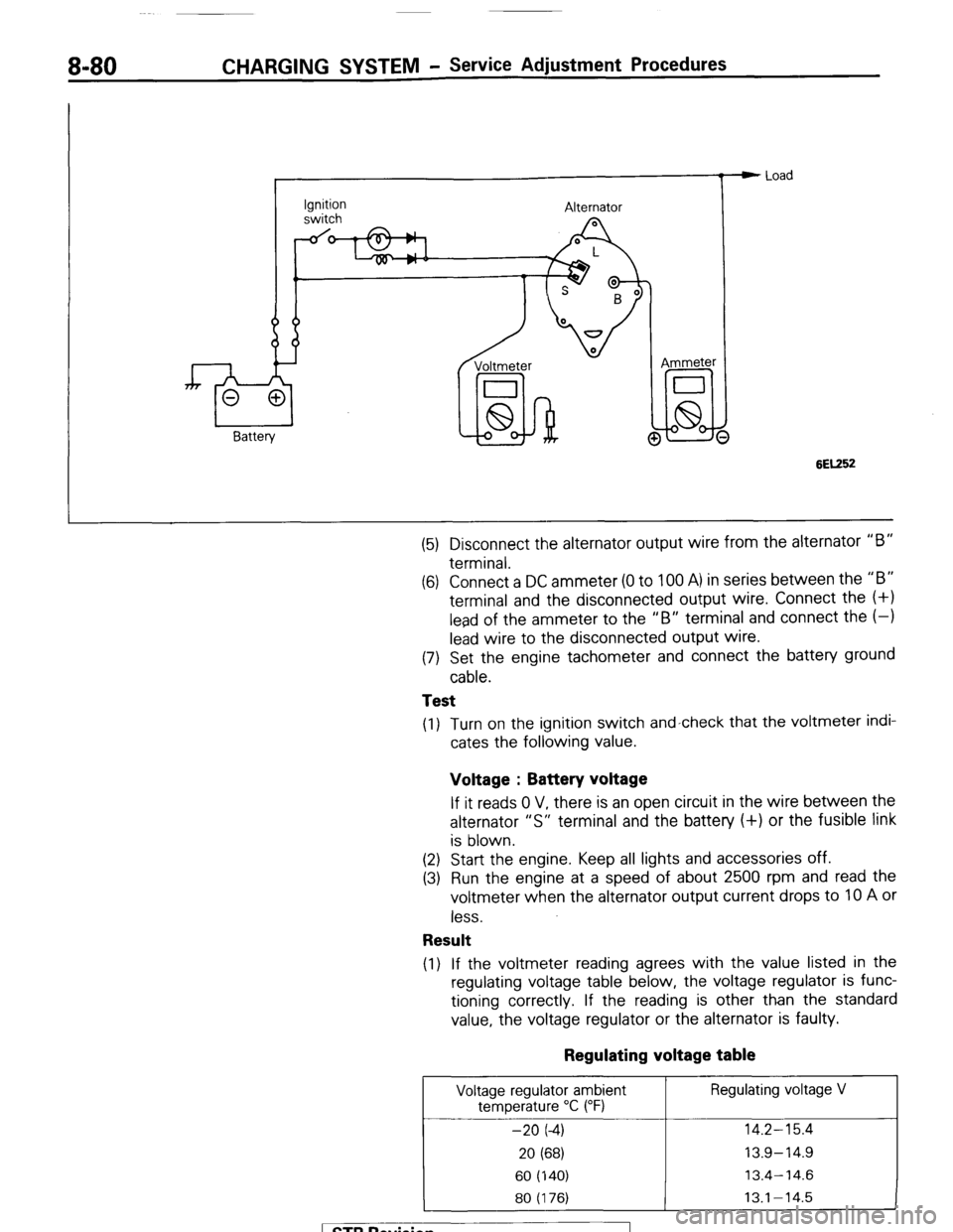
(4) Connect a digital voltmeter between the “S” terminal of the
alternator and ground. Connect the (+) lead of the voltmeter to
the “S” terminal of the alternator, inserting from the wire side
of the 2-way connector and connect the (-1 lead to sound
ground or battery (-) terminal.
1 ST6 Revision
Page 100 of 284
8-80 CHARGING SYSTEM - Service Adjustment Procedures
Ignition
switch Alternator
Voltmeter
I
lid-hi! @ Ammeter e Load
6EK52
(5) Disconnect the alternator output wire from the alternator “B”
terminal.
(6) Connect a DC ammeter (0 to 100 A) in series between the “B”
terminal and the disconnected output wire. Connect the (+I
lead of the ammeter to the “B” terminal and connect the (-1
lead wire to the disconnected output wire.
(7) Set the engine tachometer and connect the battery ground
cable.
Test
(1) Turn on the ignition switch and-check that the voltmeter indi-
cates the following value.
Voltage : Battery voltage
If it reads 0 V, there is an open circuit in the wire between the
alternator “S” terminal and the battery (+) or the fusible link
is blown.
(2) Start the engine. Keep all lights and accessories off.
(3) Run the engine at a speed of about 2500 rpm and read the
voltmeter when the alternator output current drops to 10 A or
less.
Result
(1) If the voltmeter reading agrees with the value listed in the
regulating voltage table below, the voltage regulator is func-
tioning correctly. If the reading is other than the standard
value, the voltage regulator or the alternator is faulty.
Regulating voltage table
Voltage regulator ambient Regulating voltage V
temperature “C (“F)
-20 (-4) 14.2-15.4
20 (68) 13.9-14.9
60 (140) 13.4-14.6
80 (176) 13.1-14.5
1 STB Revision
Page 131 of 284
IGNITION SYSTEM - Service Adjustment Procedures 8-111
SERVICE ADJUSTMENT PROCEDURES
CHECKING IGNITION TIMING NOEGIBA
IGNITION TIMING ADJUSTMENT
Adjustment conditions:
Coolant temperature: 80-90°C (170-I 90°F)
Lights and all accessories: Off
Transmission: N (Neutral)
1. Connect tachometer and timing light.
2. Start eng.ine and run at curb idle speed.
I
Curb idle speed rpm
First 500 km
(300 mile)
After 500 km
(300 mile)
725';;;
800 ?I00 3. To make adjustment at high altitude, disconnect pressure
sensor connector before stopping engine. Then restart
engine and run it at curb idle speed.
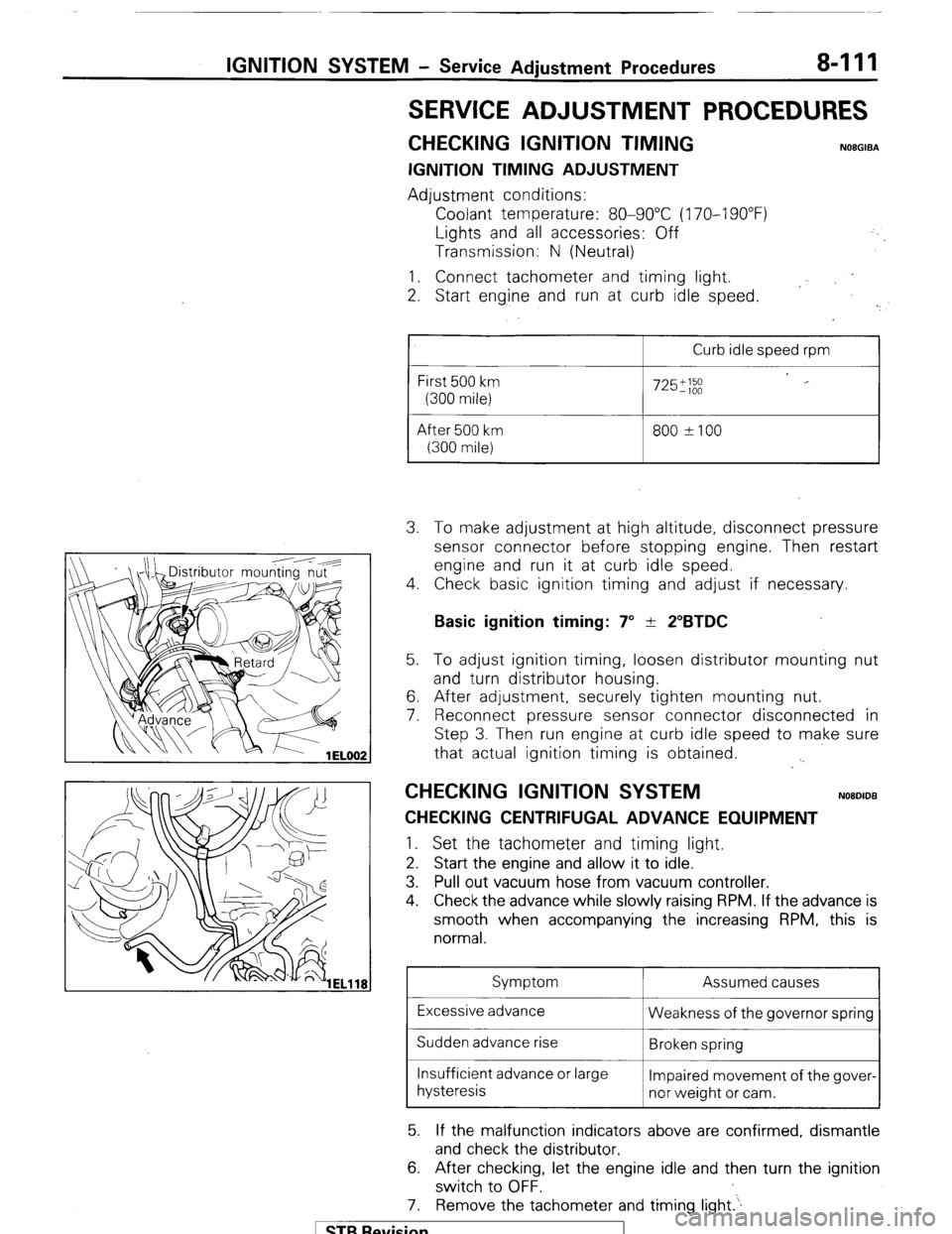
4. Check basic ignition timing and adjust if necessary.
Basic ignition timing: 7” + 2”BTDC 5. To adjust ignition timing, loosen distributor mounting nut
and turn distributor housing.
6. After adjustment, securely tighten mounting nut.
7. Reconnect pressure sensor connector disconnected in
Step 3. Then run engine at curb idle speed to make sure
that actual ignition timing is obtained.
. .
CHECKING IGNITION SYSTEM NOBDIDB
CHECKING CENTRIFUGAL ADVANCE EQUIPMENT 1.
Set the tachometer and timing light.
2. Start the engine and allow it to idle.
3. Pull out vacuum hose from vacuum controller.
4. Check the advance while slowly raising RPM. If the advance is
smooth when accompanying the increasing RPM, this is
normal.
Symptom Assumed causes
Excessive advance
Weakness of the governor spring
Sudden advance rise
Broken spring
Insufficient advance or large
Impaired movement of the gover-
hysteresis
nor weight or cam.
5. If the malfunction indicators above are confirmed, dismantle
and check the distributor.
6. After checking, let the engine idle and then turn the ignition
switch to OFF.
7. Remove the tachometer and timing light.‘.
1 STB Revision
Page 132 of 284
8-112 IGNITION SYSTEM - Service Adjustment Procedures
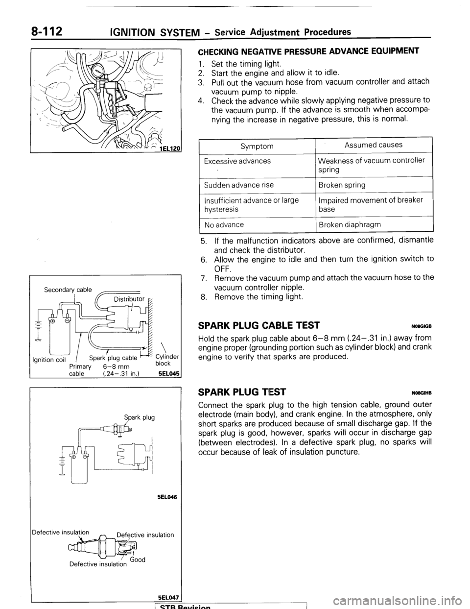
CHECKING NEGATIVE PRESSURE ADVANCE EQUIPMENT
1. Set the timing light.
2. Start the engine and allow it to idle.
3. Pull out the vacuum hose from vacuum controller and attach
vacuum pump to nipple.
4. Check the advance while slowly applying negative pressure to
the vacuum pump. If the advance is smooth when accompa-
nying the increase in negative pressure, this is normal.
Secondary cable
~~
Primaw 6-8 mm
Cylinder
block
cable ’ (.24-.31 in.) 5ELO45 1
Spark plug
5ELO46
Iefective insula
5ELO47
/
Symptom
Excessive advances
Sudden advance rise
Insufficient advance or large
hysteresis
No advance Assumed causes
Weakness of vacuum controller
spring
Broken spring
Impaired movement of breaker
base
Broken diaphragm
5. If the malfunction indicators above are confirmed, dismantle
and check the distributor.
6. Allow the engine to idle and then turn the ignition switch to
OFF.
7. Remove the vacuum pump and attach the vacuum hose to the
vacuum controller nipple.
8. Remove the timing light.
SPARK PLUG CABLE TEST NWGIGB
Hold the spark plug cable about 6-8 mm (.24-.31 in.) away from
engine proper (grounding portion such as cylinder block) and crank
engine to verify that sparks are produced.
SPARK PLUG TIEST NOUGIHB
Connect the spark plug to the high tension cable, ground outer
electrode (main body), and crank engine. In the atmosphere, only
short sparks are produced because of small discharge gap. If the
spark plug is good, however, sparks will occur in discharge gap
(between electrodes). In a defective spark plug, no sparks will
occur because of leak of insulation puncture.
fvision
I
Page 151 of 284
METERS AND GAUGES - Service Adiustment Procedures 8-131
r
(harness side) 16W834
Stopper (upper)
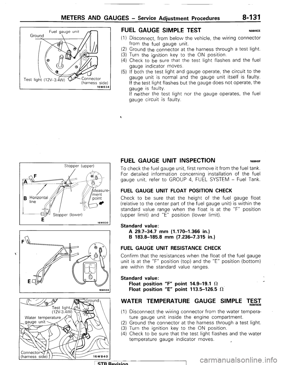
FUEL GAUGE SIMPLE TEST NOEHICE
(1) Disconnect, from below the vehicle, the wiring connector
from the fuel gauge unit.
(2) Ground the connector at the harness through a test light.
(3) Turn the ignition key to the ON position.
(4) Check to be
sure that the test light flashes and the fuel
gauge indicator moves.
(5) If both the test light and gauge operate, the circuit to the
gauge unit is normal and the gauge unit itself is faulty.
If the test light flashes but the gauge does not operate, the
gauge is faulty.
If neither the test light nor the gauge operates, the fuel
gauge circuit is faulty.
FUEL GAUGE UNIT INSPECTION NOEHIIF
To check the fuel gauge unit, first remove it from the fuel tank.
For detailed information concerning installation of the fuel
gauge unit, refer to GROUP 4, FUEL SYSTEM - Fuel Tank.
FUEL GAUGE UNIT FLOAT POSITION CHECK
Check to be sure that the height of the fuel gauge float
(relative to the center part of the fuel gauge unit) is within the
standard value range when the float is at the “F” position
(upper limit) and “E” position (lower limit).
Standard value:
A 29.7-34.7 mm (1.170-I .366 in.)
B 183.8-185.8 mm (7.236-7.315 in.)
FUEL GA&E UNIT RESISTANCE CHECK
Confirm that the resistances when the float of the fuel gauge
unit is at the “F” position (top) and the “E” position (bottom)
are within the standard value ranges.
Standard value:
Float position “F” point 14.9-19.1 IR c
Float position “E” point 113.5-126.5 IR’
WATER TEMPERATURE GAUGE SIMPLE T,5$2
(1) Disconnect the wiring connector from the water tempera-
ture gauge unit inside the engine compartment.
(2) Ground the connector at the harness through a test light.
(3) Turn the ignition key to the ON position.
(4) Check to be sure that the test light flashes and the water
temperature gauge indicator moves. ,
1 STB Revision