compression ratio MITSUBISHI MONTERO 1987 1.G Workshop Manual
[x] Cancel search | Manufacturer: MITSUBISHI, Model Year: 1987, Model line: MONTERO, Model: MITSUBISHI MONTERO 1987 1.GPages: 284, PDF Size: 14.74 MB
Page 18 of 284

18 INTRODUCTION - General Data and Specifications
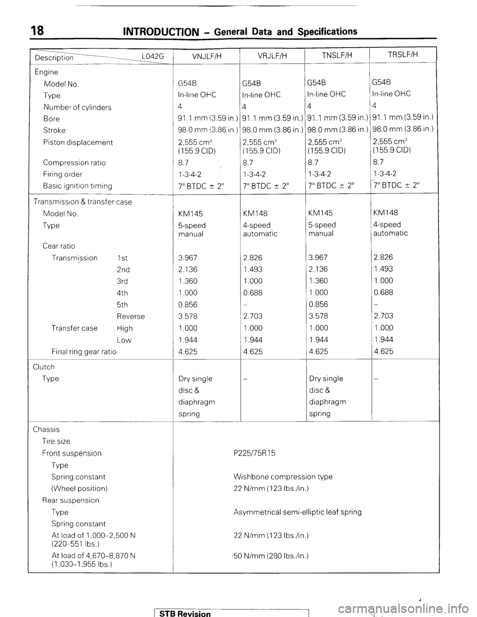
Description L042G VNJLFIH VRJ L.F/H TNSLFIH TRSLFIH
1
Engine
Model No. G54B
G54B G54B G54B
Type i In-line OHC
In-line OHC In-line OHC In-line OHC
Number of cylinders ‘4 4
4 4
Bore 91 .I mm (3.59 in.) 91 .I mm (3.59 in.) 91 ,I mm (3.59 in.) 91 .I mm (3.59 in.)
Stroke 98.0 mm (3.86 in.) 98.0 mm (3.86 in.) 98.0 mm (3.86 in.) 98.0 mm (3.86 in.)
Piston displacement
2,555 cm” 2,555 cm” 2,555 cm3
2,555 cm3
(155.9 CID) (155.9 CID) (155.9 CID) (155.9 CID)
Compression ratio 8.7
8.7 8.7
8.7
Firing order
I-3-4-2 I-3-4-2 1-3-4-2
1-3-4-2
Basic ignitron trming
7” BTDC ? 2” 7” BTDC ? 2” 7” BTDC 2 2” ‘7” BTDC ? 2”
Transmission &transfer case
Model No.
KM145 KM148 KM145 KM148
Type 5-speed 4-speed 5-speed 4-speed
manual automatic manual automatic
Cear ratio
Transmjssion 1 st
3.967 2.826 3.967
2.826
2nd
2.136 1.493 2.136
1.493
3rd 1.360
1 .ooo 1.360
1.000
4th
1.000 0.688 1 .ooo
0.688
5th
0.856 - 0.856
-
Reverse 3.578
2.703 3.578
2.703
Transfer case High 1.000
1.000 1.000
1 ,040
Low 1.944
1.944 1.944
1.944
Final ring ratio
gear 4.625 4.625 4.625
4.625
Zlutch
Type Dry single
- Dry single
-
disc & disc &
diaphragm diaphragm
spring spring
Chassis
Tire size
Front suspension
P225/75R15
Type
Spring constant
(Wheel position)
Rear suspension
Type
Spring constant
At load of 1 ,OOO-2,500 N
(220-551 Ibs.)
At load of 4,670-8,870 N
(1,030-I ,955 tbs.) Wishbone compression type
22 N/mm (123 Ibs./in.)
Asymmetrical semi-elliptic leaf spring
22 N/mm (123 Ibs./in.)
50 N/mm (280 Ibs./in.)
1 STB Revision ..,j ; : * :
Page 137 of 284

IGNITION SYSTEM-Ignition System 8417
Notch on
crankshaft
pulley
Stud 2
SERVICE POINTS OF INSTALLATION
9. INSTALLATION OF DISTRIBUTOR
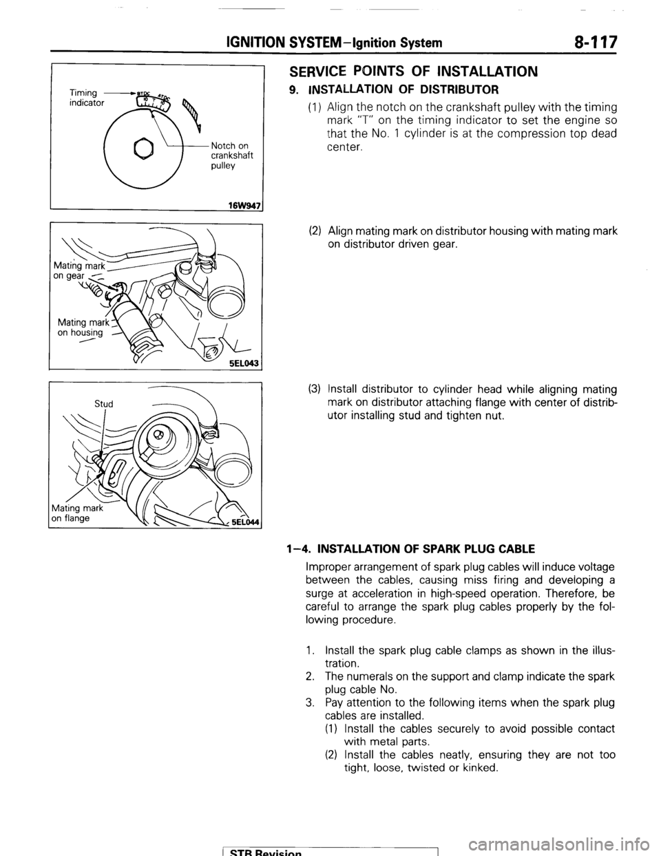
(1) Align the notch on the crankshaft pulley with the timing
mark “T” on the timing indicator to set the engine so
that the No. 1 cylinder is at the compression top dead
center.
(2) Align mating mark on distributor housing with mating mark
on distributor driven gear.
(3) Install distributor to cylinder head while aligning mating
mark on distributor attaching flange with center of distrib-
utor installing stud and tighten nut.
l-4. INSTALLATION OF SPARK PLUG CABLE
Improper arrangement of spark plug cables will induce voltage
between the cables, causing miss firing and developing a
surge at acceleration in high-speed operation. Therefore, be
careful to arrange the spark plug cables properly by the fol-
lowing procedure.
1. Install the spark plug cable clamps as shown in the illus-
tration.
2. The numerals on the support and clamp indicate the spark
plug cable No.
3. Pay attention to the following items when the spark plug
cables are installed.
(1) Install the cables securely to avoid possible contact
with metal parts.
(2) Install the cables neatly, ensuring they are not too
tight, loose, twisted or kinked.
( STB Revision
Page 268 of 284

24-32 AIR-CONDITIONING-Service Adjustment Procedures
i--
9 >
@
r
2ouo319
- 2OW627 I
Suction gauge Discharge w-w
/ I
Suction
ww Discharge
w-w
2OUO306
Suction
w-w Discharge
gauge
2OUO307
AIR CONDITIONER SWITCH
To jest the Air Conditioner Switch
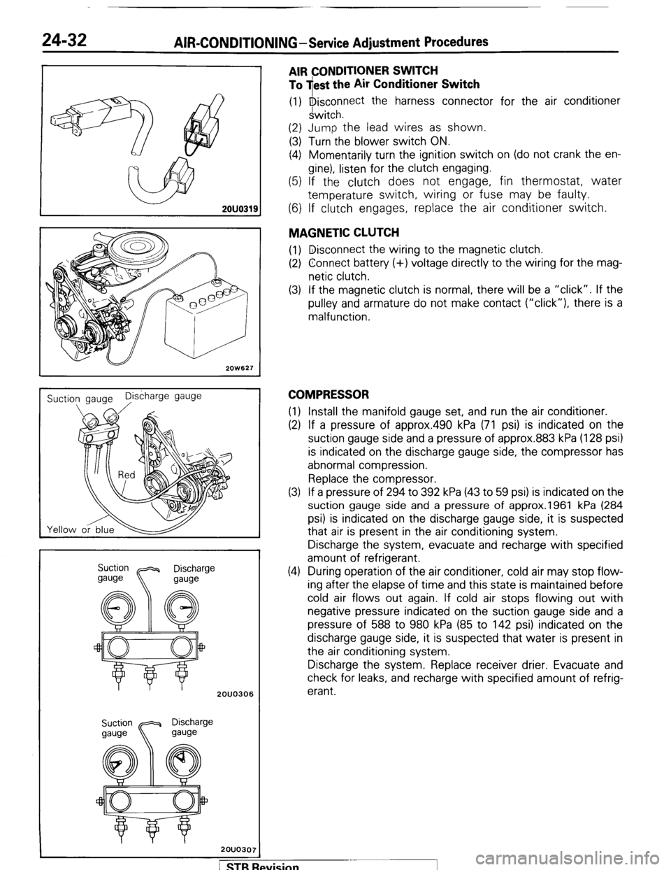
(1) Disconnect the harness connector for the air conditioner
switch.
(2) Jump the lead wires as shown.
(3) Turn the blower switch ON.
(4) Momentarily turn the ignition switch on (do not crank the en-
gine), listen for the clutch engaging.
(5) If the clutch does not engage, fin thermostat, water
temperature switch, wiring or fuse may be faulty.
(6) If clutch engages, replace the air conditioner switch.
MAGNETIC CLUTCH
(1) Disconnect the wiring to the magnetic clutch.
(2) Connect battery (+) voltage directly to the wiring for the mag-
netic clutch.
(3) If the magnetic clutch is normal, there will be a “click”. If the
pulley and armature do not make contact (“click”), there is a
malfunction.
COMPRESSOR
(1) Install the manifold gauge set, and run the air conditioner.
(2) If a pressure of approx.490 kPa (71 psi) is indicated on the
suction gauge side and a pressure of approx.883 kPa (128 psi)
is indicated on the discharge gauge side, the compressor has
abnormal compression.
Replace the compressor.
(3) If a pressure of 294 to 392 kPa (43 to 59 psi) is indicated on the
suction gauge side and a pressure of approx.1961 kPa (284
psi) is indicated on the discharge gauge side, it is suspected
that air is present in the air conditioning system.
Discharge the system, evacuate and recharge with specified
amount of refrigerant.
(4) During operation of the air conditioner, cold air may stop flow-
ing after the elapse of time and this state is maintained before
cold air flows out again. If cold air stops flowing out with
negative pressure indicated on the suction gauge side and a
pressure of 588 to 980 kPa (85 to 142 psi) indicated on the
discharge gauge side, it is suspected that water is present in
the air conditioning system.
Discharge the system. Replace receiver drier. Evacuate and
check for leaks, and recharge with specified amount of refrig-
erant.
/ STB Revision