headlight aiming MITSUBISHI MONTERO 1987 1.G Workshop Manual
[x] Cancel search | Manufacturer: MITSUBISHI, Model Year: 1987, Model line: MONTERO, Model: MITSUBISHI MONTERO 1987 1.GPages: 284, PDF Size: 14.74 MB
Page 21 of 284

8-1
ELECTRICAL
CONTENTS
NOBAA-
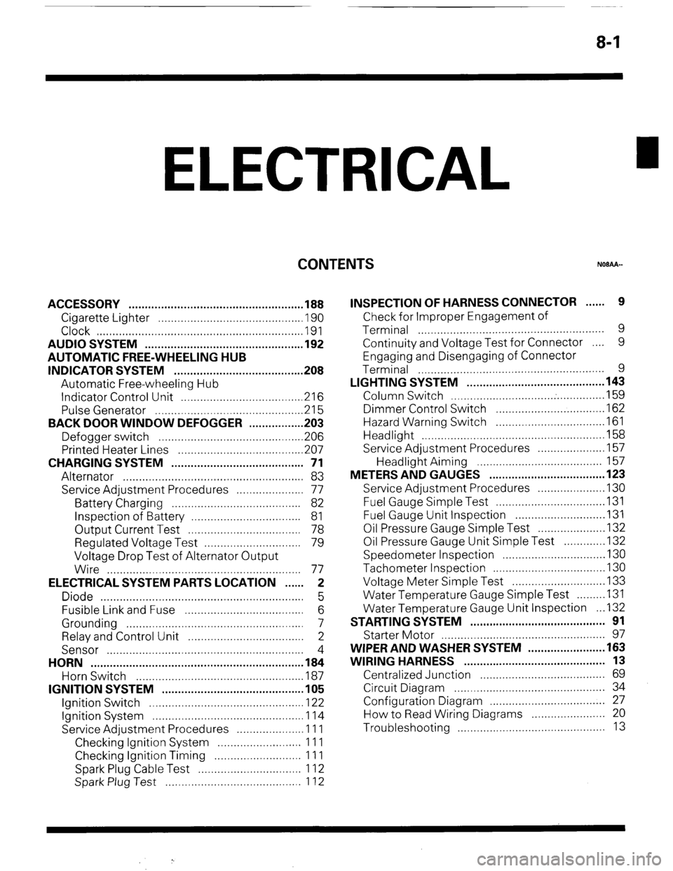
ACCESSORY ......................................................
188
Cigarette Lighter ............................................
,190
Clock ...............................................................
,191
AUDIO SYSTEM ................................................
.192
AUTOMATIC FREE-WHEELING HUB
INDICATOR SYSTEM ........................................
208
Automatic Free-wheeling Hub
Indicator Control Unit
..................................... ,216
Pulse Generator ..............................................
215
BACK DOOR WINDOW DEFOGGER
................ .203
Defogger switch ............................................
,206
Printed Heater Lines
...................................... ,207
CHARGING SYSTEM .........................................
71
Alternator ........................................................
83
Service Adjustment Procedures
..................... 77
Battery Charging ........................................
82
Inspection of Battery ..................................
81
Output Current Test ...................................
78
Regulated Voltage Test ..............................
79
Voltage Drop Test of Alternator Output
Wire ............................................................
77
ELECTRICAL SYSTEM PARTS LOCATION
...... 2
Diode ...............................................................
5
Fusible Link and Fuse
..................................... 6
Grounding .......................................................
7
Relay and Control Unit ....................................
2
Sensor .............................................................
4
HORN ..................................................................
184
Horn Switch
.................................................... 187
IGNITION SYSTEM ............................................
105
Ignition Switch
................................................ 122
Ignition System ...............................................
1 14
Service Adjustment Procedures
.................... .l 1 1
Checking Ignition System
..........................
11 1
Checking Ignition Timing
...........................
11 1
Spark Plug Cable Test
................................
1 12
Spark Plug Test
.......................................... 1 12 INSPECTION OF HARNESS CONNECTOR ...... 9
Check for Improper Engagement of
Terminal .......................................................... 9
Continuity and Voltage Test for Connector .... 9
Engaging and Disengaging of Connector
Terminal ..........................................................
9
LIGHTING SYSTEM ........................................... 143
Column Switch
................................ .
.............. .I59
Dimmer Control Switch
................................. .I62
Hazard Warning Switch
................................. .I61
Headlight ........................................................ ,158
Service Adjustment Procedures
.................... .I57
Headlight Aiming .......................................
157
METERS AND GAUGES .................................... 123
Service Adjustment Procedures
.................... .I30
Fuel Gauge Simple Test ................................. .I31
Fuel Gauge Unit Inspection ........................... .I31
Oil Pressure Gauge Simple Test
.................... .I32
Oil Pressure Gauge Unit Simple Test
............ ,132
Speedometer Inspection
............................... .I30
Tachometer Inspection .................................. ,130
Voltage Meter Simple Test
............................ .I33
Water Temperature Gauge Simple Test
....... ..I3 1
Water Temperature Gauge Unit Inspection
. ..I3 2
STARTING SYSTEM .......................................... 91
Starter Motor ............ ....................................... 97
WIPER AND WASHER SYSTEM
....................... .163
WIRING HARNESS ............................................ 13
Centralized Junction ....................................... 69
Circuit Diagram ............................................... 34
Configuration Diagram .................................... 27
How to Read Wiring Diagrams ....................... 20
Troubleshooting .............................................. 13
Page 177 of 284

LIGHTING SYSTEM - Service Adjustment Procedures 8-157
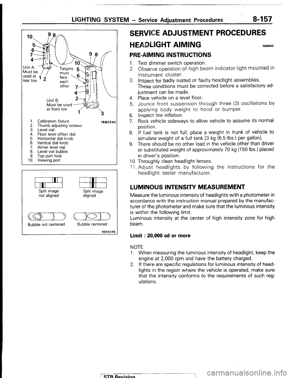
Must be used J;it A:
I ‘w ‘Targets
1. Calibration fixture
2. Thumb adjusting screws
3. Level vial
4. Floor level offset dial
5. Horizontal dial knob
6. Vertical dial knob
7. Aimer level vial
8. Level vial bubble
9. Top port hole
10. Viewing port
1660245
Split image
not aligned Split image
aligned
Bubble not centered Bubble centered
1660246
E ADJUSTMENT PROCEDURES
T AIMING
PRE-AIMING INSTRUCTIONS 1. Test dimmer switch operation.
2. Observe operation of high beam indicator light
mounted in instrument cluster.
3. Inspect for badly rusted or faulty headlight assemblies.
These conditions must be corrected before a satisfactory ad-
justment can be made.
4. Place vehicle on a level floor.
5. Jounce front suspension through three (3) oscillations by
applying body weight to hood or bumper.
6. Inspect tire inflation.
7. Rock vehicle sideways to allow vehicle to assume its normal
position.
8. If fuel tank is not full, place a weight in trunk of vehicle to
simulate weight of a full tank [3 kg (6.5 Ibs.) per gallon].
9. There should be no other load in the vehicle other than driver
or substituted weight of approximately 70 kg (150 Ibs.) placed
in driver’s position.
10. Throughly clean headlight lenses.
11. Adjust headlights by following the instructions for the
headlight tester manufacturer.
LUMINOUS INTENSITY MEASUREMENT Measure the luminous intensity of headlights with a photometer in
accordance with the instruction manual prepared by the manufac-
turer of the photometer and make sure that the luminous intensity
is within the following limit.
Luminous intensity at the center of high intensity zone for high
beam.
Limit : 20,000 cd or more NOTE
1. When measuring the luminous intensity of headlight, keep the
engine at 2,000 rpm and have the battery charged.
2. If there are specific regulations for luminous intensity of head-
lights in the region where the vehicle is operated, make sure
that the intensity conforms to the requirements of such reg-
ulations.
pTB Revision