light MITSUBISHI MONTERO 1987 1.G Workshop Manual
[x] Cancel search | Manufacturer: MITSUBISHI, Model Year: 1987, Model line: MONTERO, Model: MITSUBISHI MONTERO 1987 1.GPages: 284, PDF Size: 14.74 MB
Page 1 of 284
Service Manual
MONTERO
1987 : Volume 2
FOREWORD
This Service Manual has been prepared with the
latest service information available at the time of
publication. It is subdivided into various group
categories and each section contains diagnosis,
disassembly, repair, and installation procedures
along with complete specifications and tightening
references. Use of this manual will aid in properly
performing any servicing necessary to maintain or
restore the high levels of performance and reliability
designed into these outstanding vehicles.
WE SUPPORT
VOLUNTARY TECHNICIAN
CERTIFICATION THROUGH
MITSUBISHI MOTOR SALES OF AMERICA. Inc.
Mitsubishi Motors corporation reserves the right to make changes in
design or to make additions to or improvements in its products without
imposing any obligations upon itself to install them on its products
previously manufactured.
I
GROUP/SECTION INDEX ‘kme-.
INTRODUCTION ..............................
Electrical ...........................................
Electrical System Parts
Location .........................................
Relays, Control Units, Sensors,
Fuses, Groundings
Inspection of Harness
Connector ......................................
Wiring Harness .............................
Charging System ..........................
Starting System ............................
Ignition System .............................
Meters and Gauges ......................
Lighting System .............................
Wiper and Washer System ..........
Horn ...............................................
Accessory ......................................
Audio System ................................
Back Door Window Defogger ......
Automatic Free-wheeling Hub
Indicator System ..........................
Heaters and Air-conditioning .........
Heaters ..........................................
Air-conditioning ............................
**, For Engine Chassis & Body refer to
0 1986 Mitsubishi Motors Corporation Printed in Japan
Page 5 of 284
INTRODUCTION - Vehicle Identification
VEHICLE IDENTIFICATION NUMBER LIST
FEDERAL
VIN (except sequence number) Brand Engine displacement
JA4FJ43EoHJ
JA4FJ43EoHJ MITSUBISHI 2.555 liters
JA7FJ23EoHJ MONTERO (155.9 C.I.D.)
JA7FJ23EoHJ
5
NOOCC-
Model code
L042GVNJLF
L042GVRJLF
L042GTNSLF
L042GTRSLF
CALIFORNIA (Can also be sold in Federal states.)
VIN (except sequence number)
JA4FJ43EoHJ
JA4FJ43EoHJ
JA7FJ23EoHJ
JB7FJ23EoHJ Brand
MITSUBISHI
MONTERO Engine displacement
2.555 liters
(155.9 C.I.D.) Model code
L042GVNJLH
L042GVRJLH
L042GTNSLH
1 L042GTNSLH
OOK520
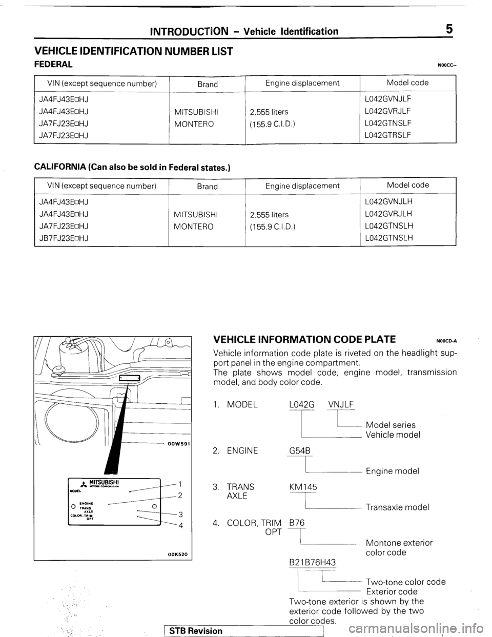
VEHICLE INFORMATION CODE PLATE NOOCO-A
Vehicle information code plate is riveted on the headlight sup-
port panel in the engine compartment.
The plate shows model code, engine model, transmission
model, and body color code.
1. MODEL L042G VNJLF
2. ENGINE G54B
I Engine model
3. TRANS
AXLE KM145
4. COLOR, TRIM
OPT 876
B2 1 B76H43
F
Two-tone exterior is shown by the Two-tone color code
Exterior code Transaxle model
Montone exterior
color code
exterior code followed by the two
color codes.
) STB Revision
._ :
Page 9 of 284
INTRODUCTION - Precautions Before Service 9
nm (in.)
so0059
PARTS
When replacing parts, use MITSUBISHI genuine parts.
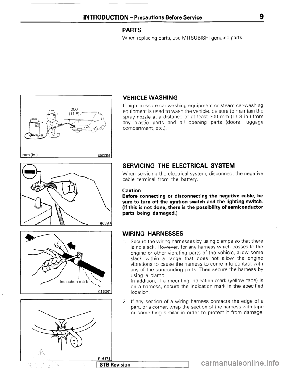
VEHICLE WVASHING
If high-pressure car-washing equipment or steam car-washing
equipment is used to wash the vehicle, be sure to maintain the
spray nozzle at a distance of at least 300 mm (1 1.8 in.) from
any plastic parts and all opening parts (doors, luggage
compartment, etc.).
SERVICING THE ELECTRICAL SYSTEM
When servicing the electrical system, disconnect the negative
cable terminal from the battery.
Caution
Before connecting or disconnecting the negative cable, be
sure to turn off the ignition switch and the lighting switch.
(If this is not done, there is the possibility of semiconductor
parts being damaged.)
WIRING HARNESSES
1. Secure the wiring harnesses by using clamps so that there
is no slack. However, for any harness which passes to the
engine or other vibrating parts of the vehicle, allow some
slack within a range that does not allow the engine
vibrations to cause the harness to come into contact with
any of the surrounding parts. Then secure the harness by
using a clamp.
In addition, if a mounting indication mark (yellow tape) is
on a harness, secure the indication mark in the specified
location.
2. If any section of a wiring harness contacts the edge of a
part, or a corner, wrap the section of the harness with tape
or something similar in order to protect it from damage.
F161711
* :, :, 1 STB Revision
Page 14 of 284
INTRODUCTION - Towing and Hoisting
TOWING AND HOISTING NOOGA-
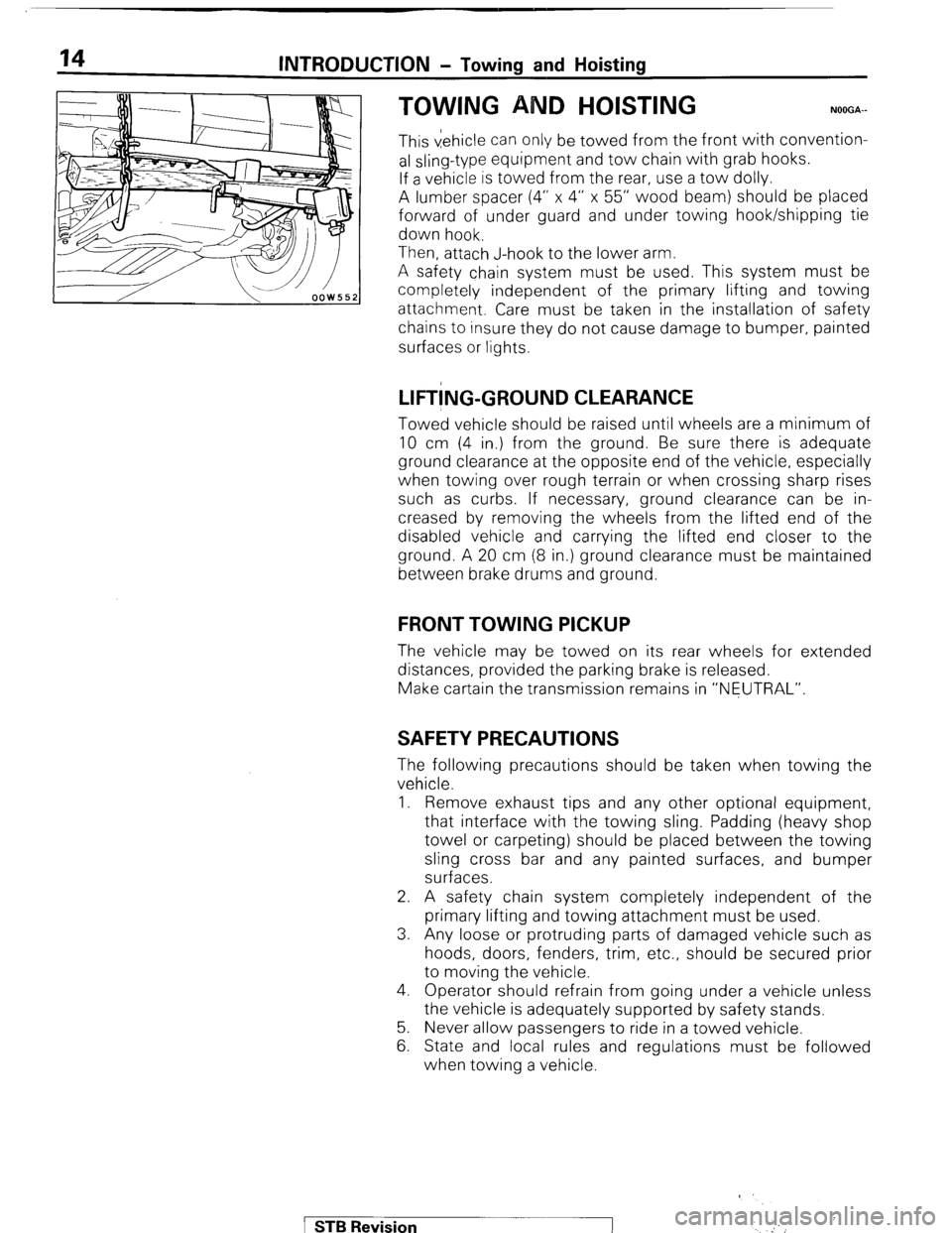
This vehicle can only be towed from the front with convention-
al sling-type equipment and tow chain with grab hooks.
If a vehicle is towed from the rear, use a tow dolly.
A lumber spacer (4” x 4” x 55” wood beam) should be placed
forward of under guard and under towing hook/shipping tie
down hook.
Then, attach J-hook to the lower arm.
A safety chain system must be used. This system must be
completely independent of the primary lifting and towing
attachment. Care must be taken in the installation of safety
chains to insure they do not cause damage to bumper, painted
surfaces or lights.
LIFT!NG-GROUND CLEARANCE
Towed vehicle should be raised until wheels are a minimum of
10 cm (4 in.) from the ground. Be sure there is adequate
ground clearance at the opposite end of the vehicle, especially
when towing over rough terrain or when crossing sharp rises
such as curbs. If necessary, ground clearance can be in-
creased by removing the wheels from the lifted end of the
disabled vehicle and carrying the lifted end closer to the
ground. A 20 cm (8 in.) ground clearance must be maintained
between brake drums and ground.
FRONT TOWING PICKUP
The vehicle may be towed on its rear wheels for extended
distances, provided the parking brake is released.
Make cartain the transmission remains in “NEUTRAL”.
SAFETY PRECAUTIONS
The following precautions should be taken when towing the
vehicle.
1. Remove exhaust tips and any other optional equipment,
that interface with the towing sling. Padding (heavy shop
towel or carpeting) should be placed between the towing
sling cross bar and any painted surfaces, and bumper
surfaces.
2. A safety chain system completely independent of the
primary lifting and towing attachment must be used.
3. Any loose or protruding parts of damaged vehicle such as
hoods, doors, fenders, trim, etc., should be secured prior
to moving the vehicle.
4. Operator should refrain from going under a vehicle unless
the vehicle is adequately supported by safety stands.
5. Never allow passengers to ride in a towed vehicle.
6. State and local rules and regulations must be followed
when towing a vehicle.
1 STB Revision
‘
Page 21 of 284
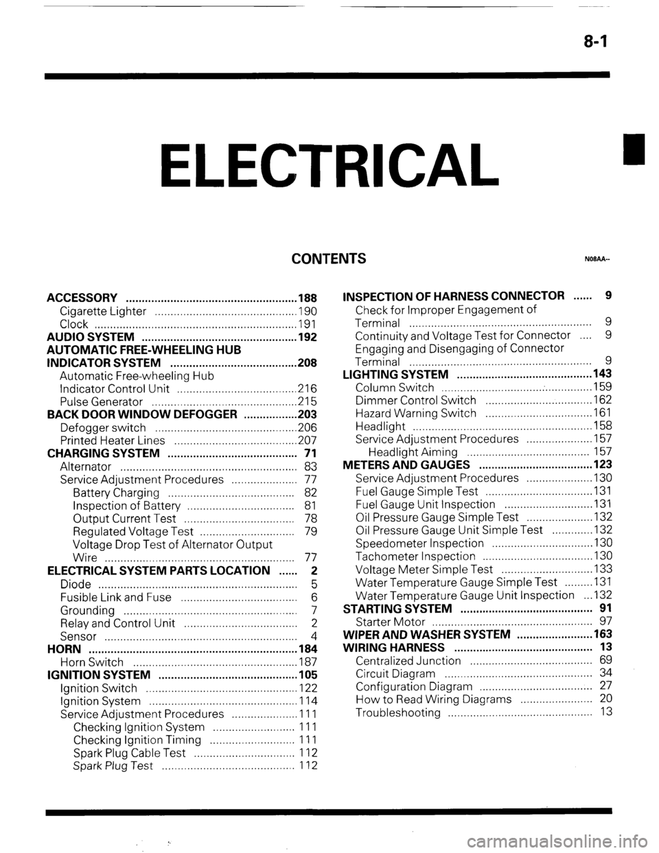
8-1
ELECTRICAL
CONTENTS
NOBAA-
ACCESSORY ......................................................
188
Cigarette Lighter ............................................
,190
Clock ...............................................................
,191
AUDIO SYSTEM ................................................
.192
AUTOMATIC FREE-WHEELING HUB
INDICATOR SYSTEM ........................................
208
Automatic Free-wheeling Hub
Indicator Control Unit
..................................... ,216
Pulse Generator ..............................................
215
BACK DOOR WINDOW DEFOGGER
................ .203
Defogger switch ............................................
,206
Printed Heater Lines
...................................... ,207
CHARGING SYSTEM .........................................
71
Alternator ........................................................
83
Service Adjustment Procedures
..................... 77
Battery Charging ........................................
82
Inspection of Battery ..................................
81
Output Current Test ...................................
78
Regulated Voltage Test ..............................
79
Voltage Drop Test of Alternator Output
Wire ............................................................
77
ELECTRICAL SYSTEM PARTS LOCATION
...... 2
Diode ...............................................................
5
Fusible Link and Fuse
..................................... 6
Grounding .......................................................
7
Relay and Control Unit ....................................
2
Sensor .............................................................
4
HORN ..................................................................
184
Horn Switch
.................................................... 187
IGNITION SYSTEM ............................................
105
Ignition Switch
................................................ 122
Ignition System ...............................................
1 14
Service Adjustment Procedures
.................... .l 1 1
Checking Ignition System
..........................
11 1
Checking Ignition Timing
...........................
11 1
Spark Plug Cable Test
................................
1 12
Spark Plug Test
.......................................... 1 12 INSPECTION OF HARNESS CONNECTOR ...... 9
Check for Improper Engagement of
Terminal .......................................................... 9
Continuity and Voltage Test for Connector .... 9
Engaging and Disengaging of Connector
Terminal ..........................................................
9
LIGHTING SYSTEM ........................................... 143
Column Switch
................................ .
.............. .I59
Dimmer Control Switch
................................. .I62
Hazard Warning Switch
................................. .I61
Headlight ........................................................ ,158
Service Adjustment Procedures
.................... .I57
Headlight Aiming .......................................
157
METERS AND GAUGES .................................... 123
Service Adjustment Procedures
.................... .I30
Fuel Gauge Simple Test ................................. .I31
Fuel Gauge Unit Inspection ........................... .I31
Oil Pressure Gauge Simple Test
.................... .I32
Oil Pressure Gauge Unit Simple Test
............ ,132
Speedometer Inspection
............................... .I30
Tachometer Inspection .................................. ,130
Voltage Meter Simple Test
............................ .I33
Water Temperature Gauge Simple Test
....... ..I3 1
Water Temperature Gauge Unit Inspection
. ..I3 2
STARTING SYSTEM .......................................... 91
Starter Motor ............ ....................................... 97
WIPER AND WASHER SYSTEM
....................... .163
WIRING HARNESS ............................................ 13
Centralized Junction ....................................... 69
Circuit Diagram ............................................... 34
Configuration Diagram .................................... 27
How to Read Wiring Diagrams ....................... 20
Troubleshooting .............................................. 13
Page 22 of 284
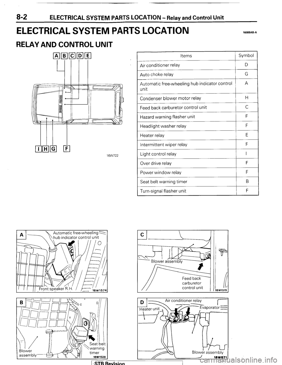
8-2 ELECTRICAL SYSTEM PARTS LOCATION - Relay and Control Unit
ELECTRICAL SYSTEM IPARTS LOCATION NOIBAB-A
RELAY AND CONTROL UNIT
16W722
n 17
hub indicator control unit A A Automatic free-wheeling 2
Blower
assembiy& x v/i 16W152B Items Symbol
--
Air conditioner relay D
--
Auto choke relay G
--
Automatic free-wheeling hub indicator control
A
unit
Condenser blower motor relay H
Feed back carburetor control unit C
Hazard warning flasher unit F
Headlight washer relay F
Heater relay E
Intermittent wiper relay F
~___
Light control relay I
~___
Over drive relay F
Power window relay F
Seat belt warning timer B
Turn-signal flasher unit F
carburetor
control unit
Air conditioner relay
d--- I- Jr Evaporator E
1 .STB Re\iision
Page 23 of 284
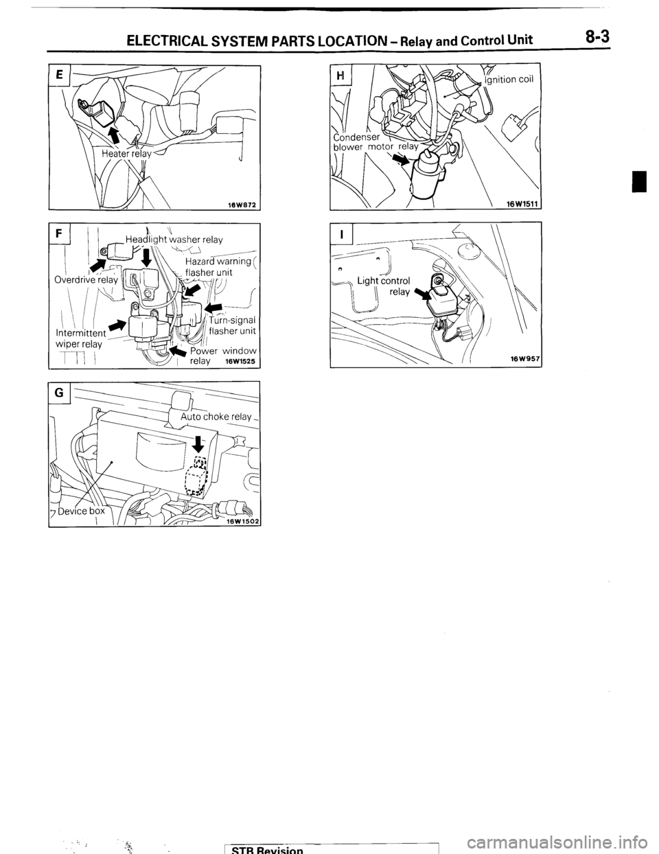
ELECTRICAL SYSTEM PARTS LOCATION - Relay and Control Unit 8-3
FI)I h” -Headlight washer relay
k\\ Hazard warnina f
1 STB Revision
Page 25 of 284
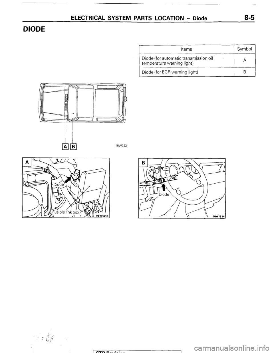
DIODE
ELECTRICAL SYSTEM PARTS LOCATION - Diode 8-5
Diode (for automatic transmission oil
Diode (for EGR warning light)
1 @NJ22
STB Revision
Page 26 of 284
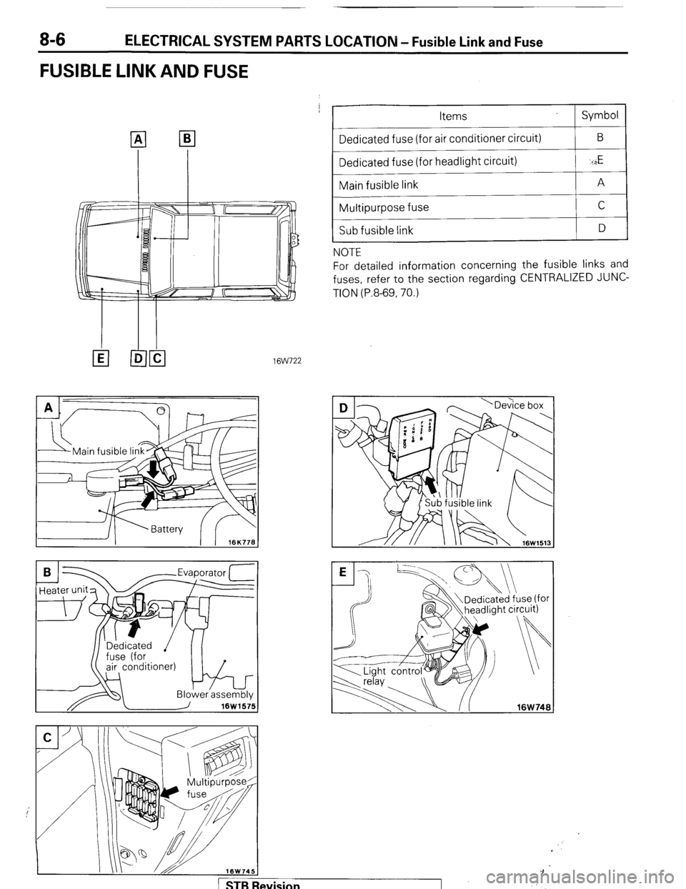
ELECTRICAL SYSTEM PARTS LOCATION - Fusible Link and Fuse
FUSIBLE LINK AND FUSE
--
Items
Dedicated fuse (for air conditioner circuit)
Dedicated fuse (for headlight circuit)
Main fusible link
Multipurpose fuse
Sub fusible link
NOTE Symbol
B
‘I
E
A
C
D
For detailed information concerning the fusible links and
fuses, refer to the section regarding CENTRALIZED JUNC-
TION (P.8-69, 70.)
16W722
-Evaoorator 1
/ STBI levision
Page 27 of 284
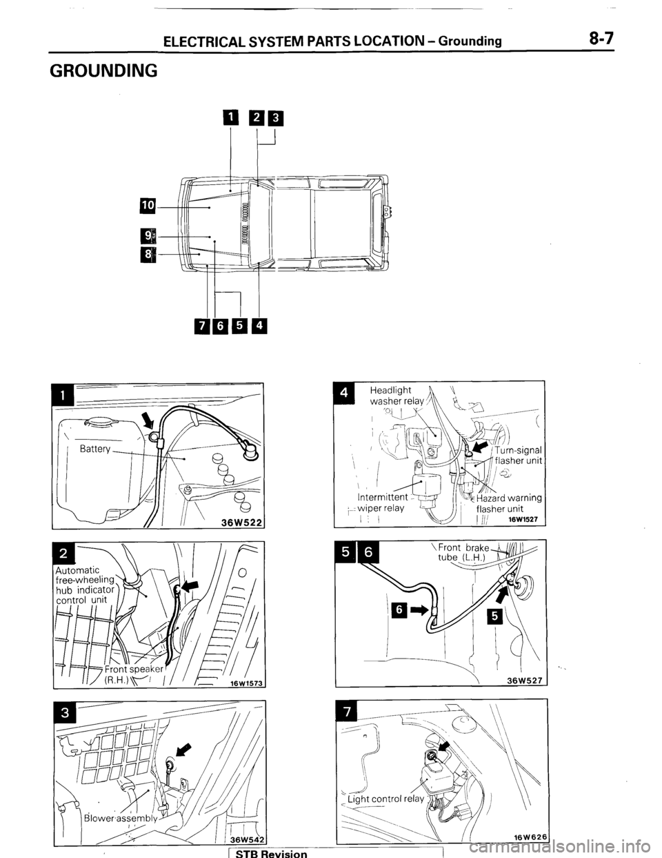
ELECTRICAL SYSTEM PARTS LOCATION -Grounding 8-7
GROUNDING
I
Headlight
washer relay,
h !Ja -/
_ .-----
/ 1 STB Revision