key MITSUBISHI MONTERO 1987 1.G Workshop Manual
[x] Cancel search | Manufacturer: MITSUBISHI, Model Year: 1987, Model line: MONTERO, Model: MITSUBISHI MONTERO 1987 1.GPages: 284, PDF Size: 14.74 MB
Page 53 of 284
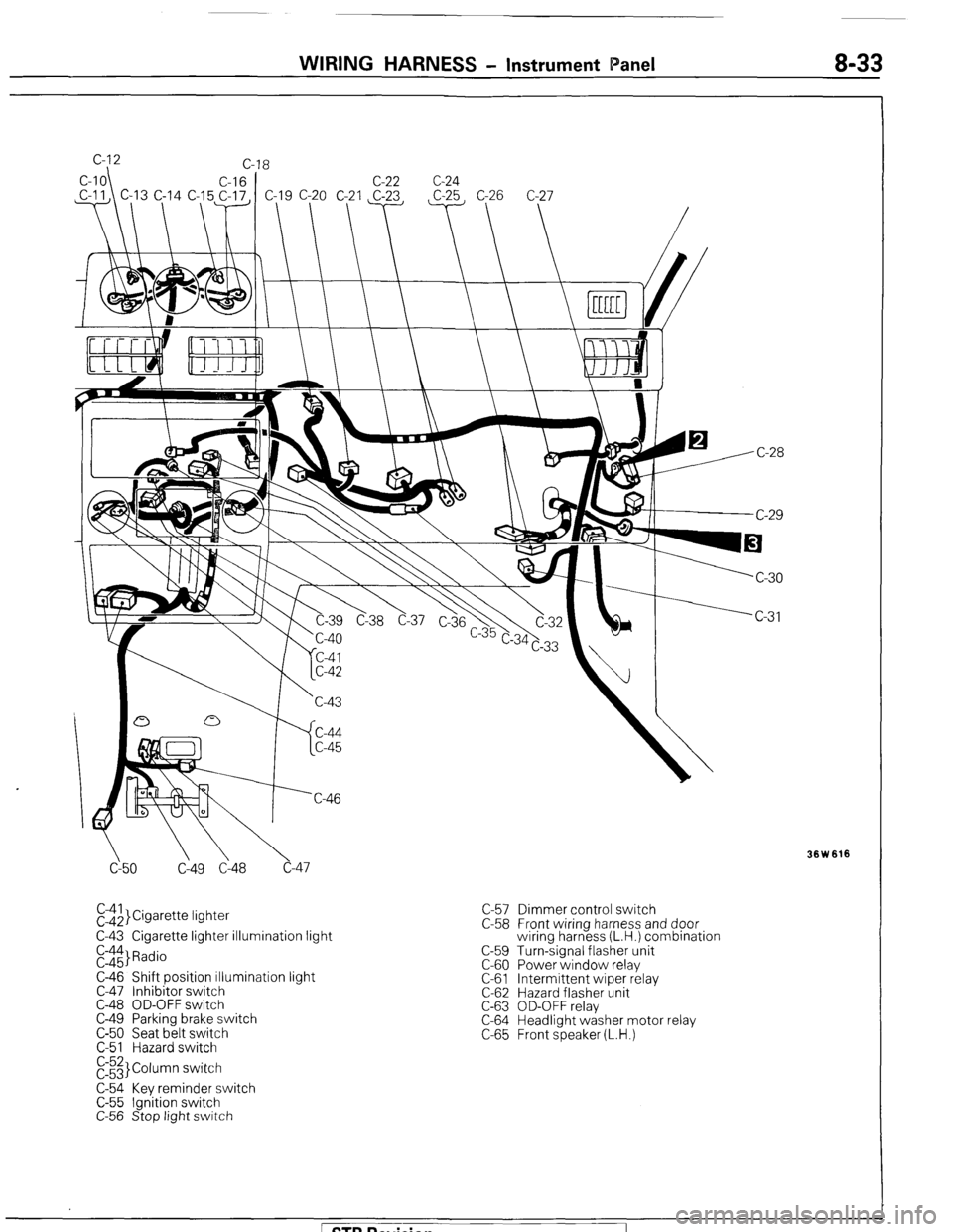
WIRING HARNESS - Instrument Panel 8-33
cy50 C149 Cl48 c-47
El$,}Cigarette lightet
C-43 Cigarette lighter illumination light
E::$ Radio
C-46 Shift position illumination light
C-47 Inhibitor switch
C-48 OD-OFF switch
C-49 Parking brake switch
C-50 Seat belt switch
C-51 Hazard switch
E3 Column switch
C-54 Key reminder switch
C-55 Ignition switch
C-56 Stop light switch C-57 Dimmer control switch
C-58 Front wiring harness and door
wiring harness (L.H.) combination
C-59 Turn-signal flasher unit
C-60 Power window relay
C-61 Intermittent wiper relay
C-62 Hazard flasher unit
C-63 OD-OFF relay
C-64 Headlight washer motor relay
C-65 Front speaker (L.H.)
Ision
Page 86 of 284
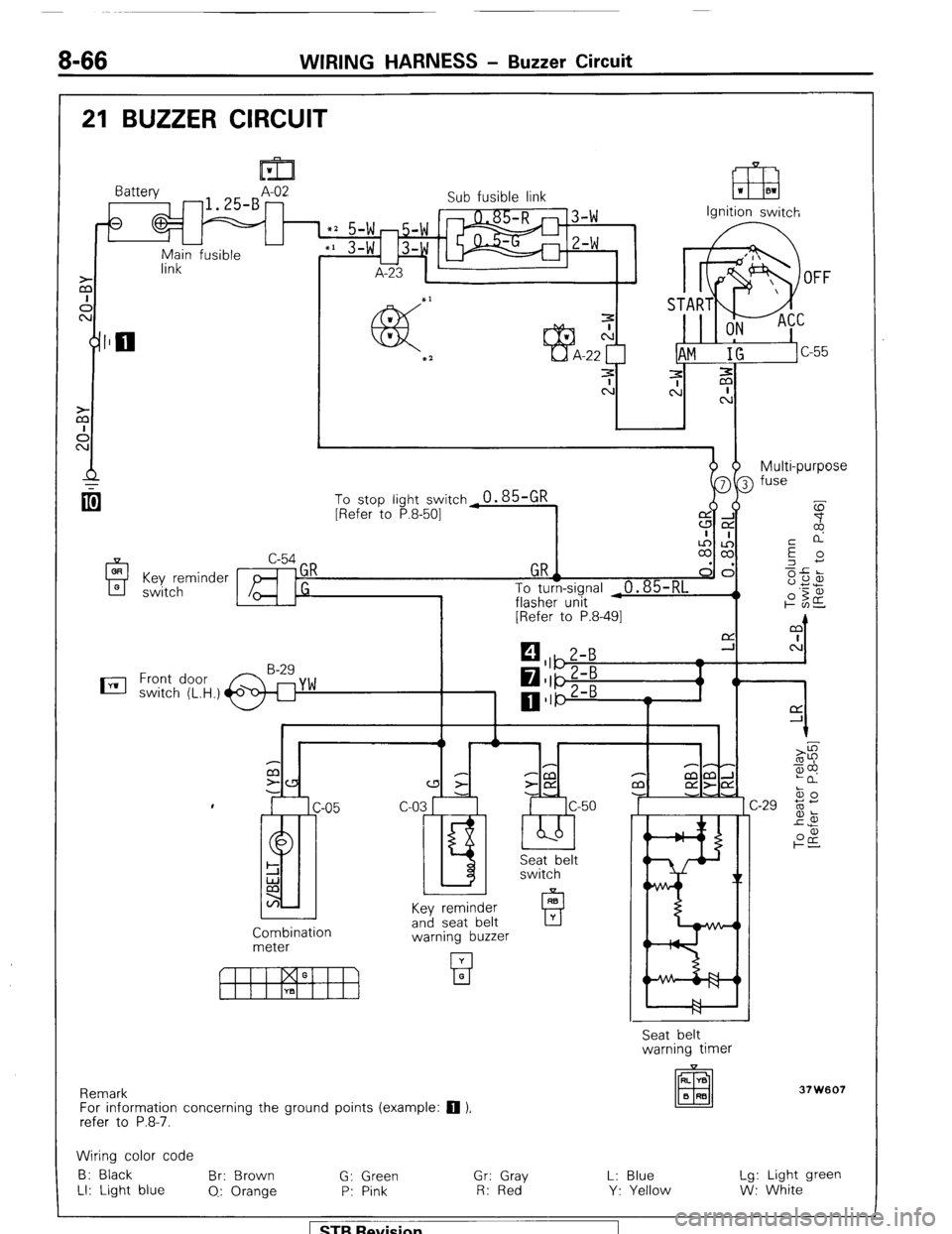
8-66 WIRING HARNESS - Buzzer Circuit
21 BUZZER CIRCUIT
OR
A 0 Key reminder
switch
nil 1
link Battery A-02
-1.25-B -
0
-
Main fusible Sub fusible link
IT8 ‘I 01
Ignition switch
dhm b- Multi-purpose
[Refer to P.8-491
0 1
C P-P
a 3
-CCl P mm-l
z- z-CY m aa-cd
c-03 r c-50 -J -.A
I.5 ‘bb’ IC ski&t
switch
Key reminder
Combination
meter and seat belt
warning buzzer
Remark
For information concerning the ground points (example:
q ),
refer to P.8-7. Seat belt
warning timer
37W607
Wiring color code
B: Black Br: Brown
G: Green Gr: Gray L: Blue Lg: Light green
LI: Light blue
0.: Orange P: Pink R: Red Y: Yellow W: White 1 ST9 Revision
Page 90 of 284
WIRING HARNESS - Centralized Junction
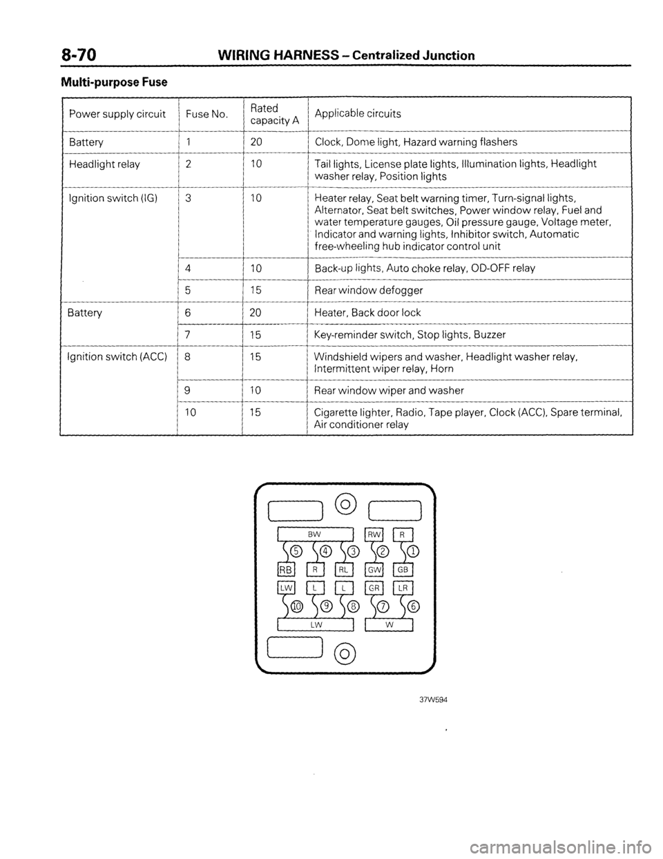
Multi-purpose Fuse
Power supply circuit Fuse No. Rated
capacity A Applicable circuits
Battery 1 20
Clock, Dome light, Hazard warning flashers
Headlight relay 2 10 Tail lights, License plate lights, Illumination lights, Headlight
washer relay, Position lights
__-
Ignition switch (IG) 3 10 Heater relay, Seat belt warning timer, Turn-signal lights,
Alternator, Seat belt switches, Power window relay, Fuel and
water temperature gauges, Oil pressure gauge, Voltage meter,
Indicator and warning lights, Inhibitor switch, Automatic
free-wheeling hub indicator control unit
4
IO Back-up lights, Auto choke relay, OD-OFF relay
__-
5 15 Rear window defogger
Battery 6 20 Heater, Back door lock
7 15 Key-reminder switch, Stop lights, Buzzer
Ignition switch (ACC) 8 15 Windshield wipers and washer, Headlight washer relay,
Intermittent wiper relay, Horn
9 10 Rear window wiper and washer
10 15 Cigarette lighter, Radio, Tape player, Clock (ACC), Spare terminal,
Air conditioner relay
Page 127 of 284
IGNITION SYSTEM - Specifications 8-107
SPECIFICATIONS
GENERAL SPECIFICATIONS
DISTRIBUTOR N08GB.B
Type
Model No.
Part No.
Igniter
Firing order Items Federal
Contact pointless type
T3T61980A
MD109013
Built-in type
1-3-4-2 California
Contact pointless type
T3T65571
MD1 10264
Built-in type
1-3-4-2
IGNITION COIL
Type
Model No.
Part No. Items
Oil filled
E-089
M DO73079 Specifications
SPARK PLUG
Items
Factory installed plug Model No. Manifacturer
W20EP-U 10 NIPPON DENS0
W20EPR-Sll
BURGEA-1 1
Alternate plug BPGES-1 1
BPRGES-1 1
BUGEA-11 NGK
W20EPR-U IO
W20EPSll NIPPON DENS0
IGNITION SWITCH
Items
ignition switch
Load capacity
AM-ACC
AM-IG
AM-ST
AM-R
Voltage drop (under actual load)
Key reminder switch
Rated load
Voltage drop Specifications
15A
30A
15A
15A
0.1 V or less
IW
0.2 V or less
) STB Revision
Page 142 of 284
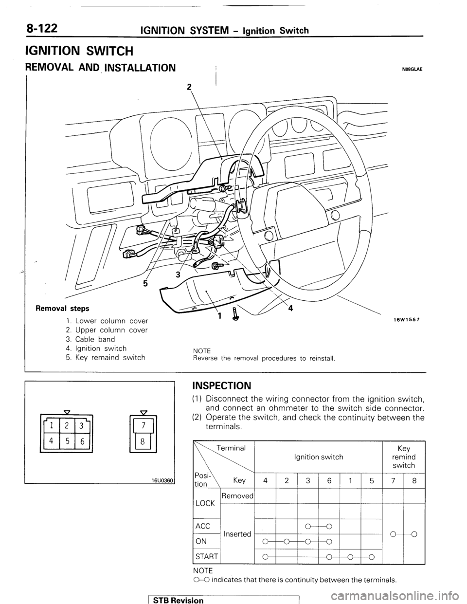
8-122 IGNITION SYSTEM - Ugnition Switch
IGNITION SWITCH
REMOVAL AND INSTALLATION
Removal steps
1. Lower column cover
2. Upper column cover
3. Cable band
4. Ignition switch
5. Key remaind switch NOTE Reverse the removal procedures to reinstall
NOEGLAE
16W1557
16UO36C
!I
INSPECTION (1) Disconnect the wiring connector
from the ignition switch,
and connect an ohmmeter to the
switch side connector. (2) Operate the switch, and check the continuity between the
terminals.
START / Ignition switch
NOTE
O-C indicates that there is continuity between the terminals. 1 STB Revision -7
Page 147 of 284
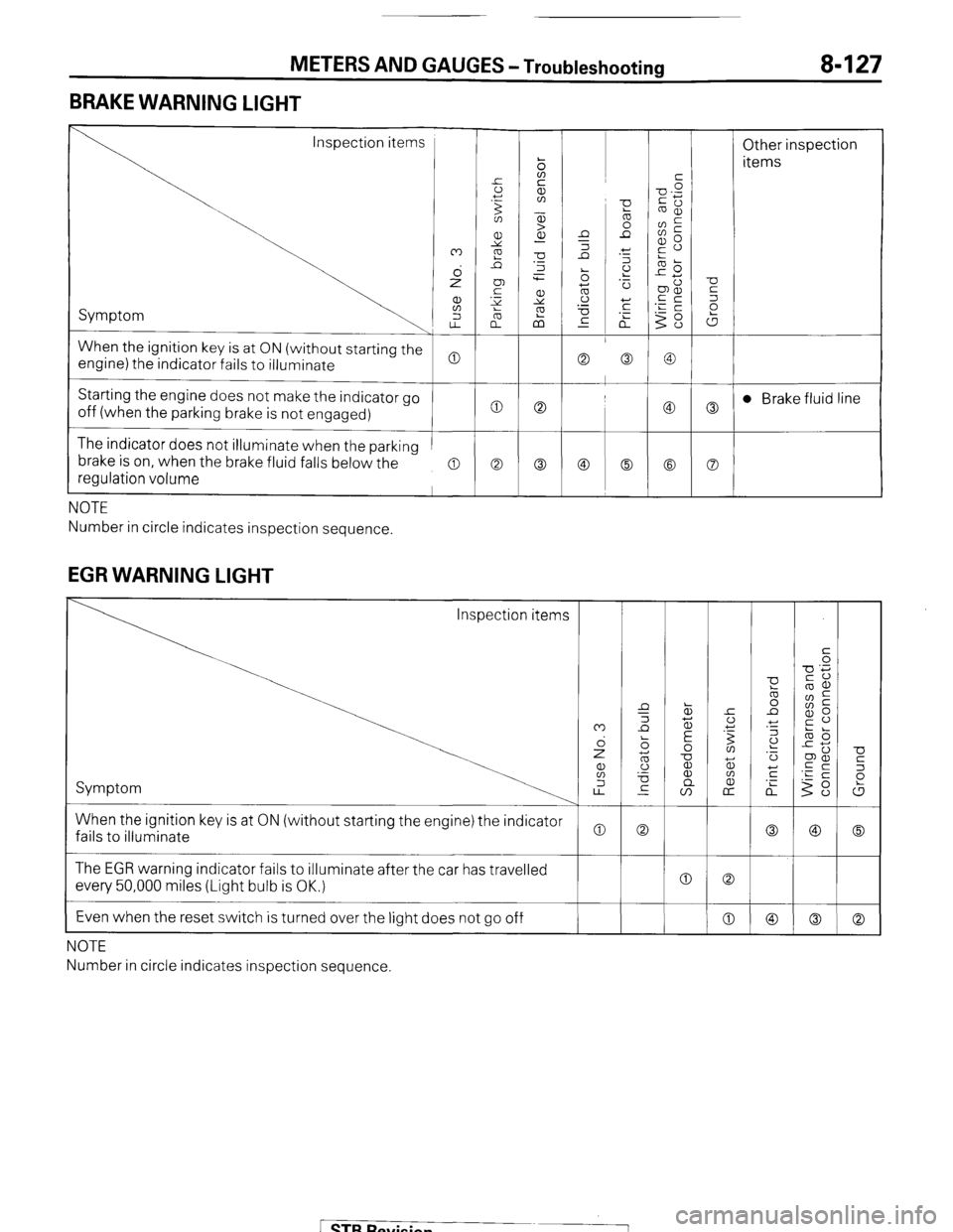
METERS AND GAUGES -Troubleshooting 8-127
BRAKE WARNING LIGHT
Inspection items
Other inspection
items
Symptom
When the ignition key is at ON (without starting the
engine) the indicator fails to illuminate
Starting the engine does not make the indicator go
off (when the parking brake is not engaged) t 0 0
c
The indicator does not illuminate when the parking
brake is on, when the brake fluid falls below the
regulation volume
a a Co
NOTE
Number in circle indicates inspection sequence.
EGR WARNING LIGHT
U
5
P
W
0
Co When the ignition key is at ON (without starting the engine) the indicator
fails to illuminate
0 The EGR warning indicator fails to illuminate after the car has travelled
every 50,000 miles (Light bulb is OK.)
Even when the reset switch is turned over the light does not go off 0 0
0
I
NOTE
Number in circle indicates inspection sequence.
[ STB Revision
Page 151 of 284
METERS AND GAUGES - Service Adiustment Procedures 8-131
r
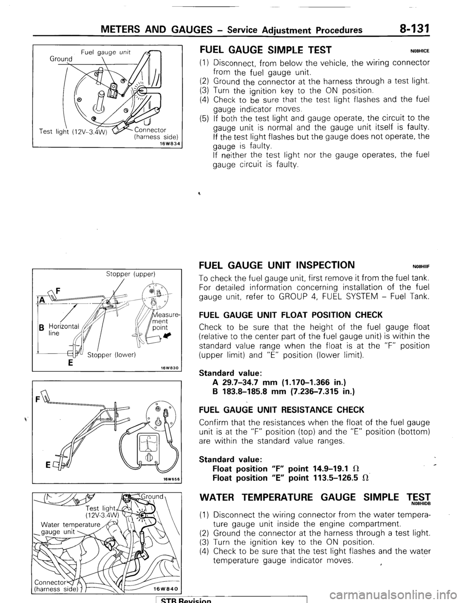
(harness side) 16W834
Stopper (upper)
FUEL GAUGE SIMPLE TEST NOEHICE
(1) Disconnect, from below the vehicle, the wiring connector
from the fuel gauge unit.
(2) Ground the connector at the harness through a test light.
(3) Turn the ignition key to the ON position.
(4) Check to be
sure that the test light flashes and the fuel
gauge indicator moves.
(5) If both the test light and gauge operate, the circuit to the
gauge unit is normal and the gauge unit itself is faulty.
If the test light flashes but the gauge does not operate, the
gauge is faulty.
If neither the test light nor the gauge operates, the fuel
gauge circuit is faulty.
FUEL GAUGE UNIT INSPECTION NOEHIIF
To check the fuel gauge unit, first remove it from the fuel tank.
For detailed information concerning installation of the fuel
gauge unit, refer to GROUP 4, FUEL SYSTEM - Fuel Tank.
FUEL GAUGE UNIT FLOAT POSITION CHECK
Check to be sure that the height of the fuel gauge float
(relative to the center part of the fuel gauge unit) is within the
standard value range when the float is at the “F” position
(upper limit) and “E” position (lower limit).
Standard value:
A 29.7-34.7 mm (1.170-I .366 in.)
B 183.8-185.8 mm (7.236-7.315 in.)
FUEL GA&E UNIT RESISTANCE CHECK
Confirm that the resistances when the float of the fuel gauge
unit is at the “F” position (top) and the “E” position (bottom)
are within the standard value ranges.
Standard value:
Float position “F” point 14.9-19.1 IR c
Float position “E” point 113.5-126.5 IR’
WATER TEMPERATURE GAUGE SIMPLE T,5$2
(1) Disconnect the wiring connector from the water tempera-
ture gauge unit inside the engine compartment.
(2) Ground the connector at the harness through a test light.
(3) Turn the ignition key to the ON position.
(4) Check to be sure that the test light flashes and the water
temperature gauge indicator moves. ,
1 STB Revision
Page 152 of 284
8-132 METERS AND GAUGES - Service Adjustment Procedures
(5) If both the test light and gauge operate, the circuit to the
gauge unit is normal and the gauge unit itself is faulty.
If the test light flashes but the gauge does not operate, the
gauge is faulty.
If 1 neither the test light nor the gauge operates, the water
temperature gauge circuit is faulty.
Se
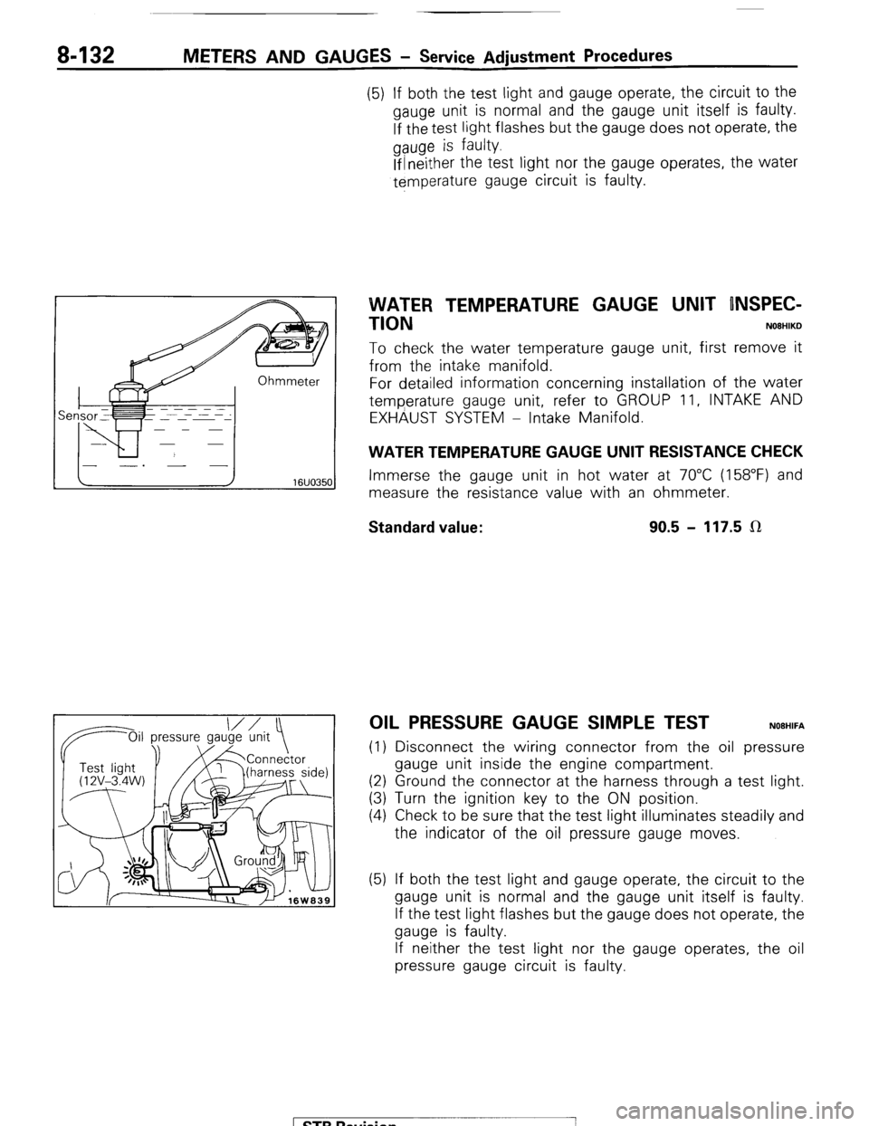
VVATER TEMPERATURE GAUGE UNIT ONSPEC-
TION
NOBHIKD
To check the water temperature gauge unit, first remove it
from the intake manifold.
For detailed information concerning installation of the water
temperature gauge unit, refer to GROUP 11, INTAKE AND
EXHAUST SYSTEM - Intake Manifold.
WATER TEMPERATURE GAUGE UNIT RESISTANCE CHECK
Immerse the gauge unit in hot water at 70°C (158°F) and
measure the resistance value with an ohmmeter.
Standard value: 90.5 - 117.5 LR
OIL PRESSURE GAUGE SIMPLE TEST NOEHIFA
(1) Disconnect the wiring connector from the oil pressure
gauge unit inside the engine compartment.
(2) Ground the connector at the harness through a test light.
(3) Turn the ignition key to the ON position.
(4) Check to be sure that the test light illuminates steadily and
the indicator of the oil pressure gauge moves.
(5) If both the test light and gauge operate, the circuit to the
gauge unit is normal and the gauge unit itself is faulty.
If the test light flashes but the gauge does not operate, the
gauge is faulty.
If neither the test light nor the gauge operates, the oil
pressure gauge circuit is faulty.
1 STB Revision
-7
Page 153 of 284
METERS AND GAUGES - Service Adjustment Procedures 8-133
IOil p Oil pressure ressure
gauge unit
1 I Test light
‘@‘(12V - 3.4 I
W)
16W1576
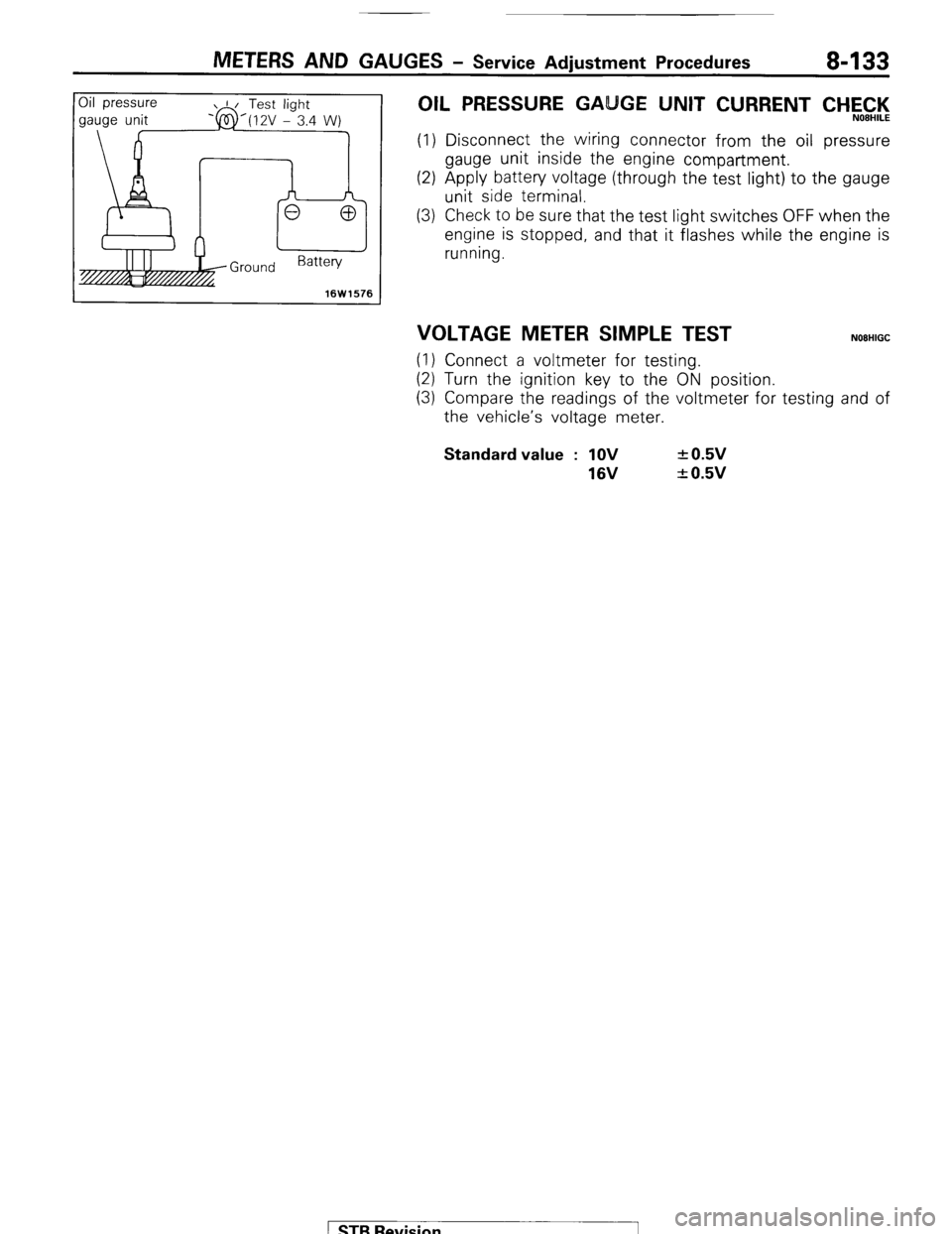
OIL PRESSURE GA GE UNIT CURRENT CHEC,‘l<,
(1) Disconnect the wiring connector from the oil pressure
gauge unit inside the engine compartment.
(2) Apply battery voltage (through the test light) to the gauge
unit side terminal.
(3) Check to be sure that the test light switches OFF when the
engine is stopped, and that it flashes while the engine is
running.
VOLTAGE METER SIMPLE TEST NOEHIGC
(1) Connect a voltmeter for testing.
(2) Turn the ignition key to the ON position.
(3) Compare the readings of the voltmeter for testing and of
the vehicle’s voltage meter. Standard value : 1OV
16V + 0.5v
+ 0.5v
1 STB Revision
Page 161 of 284
METERS AND GAUGES - Indicators and Warning Lights 8-141
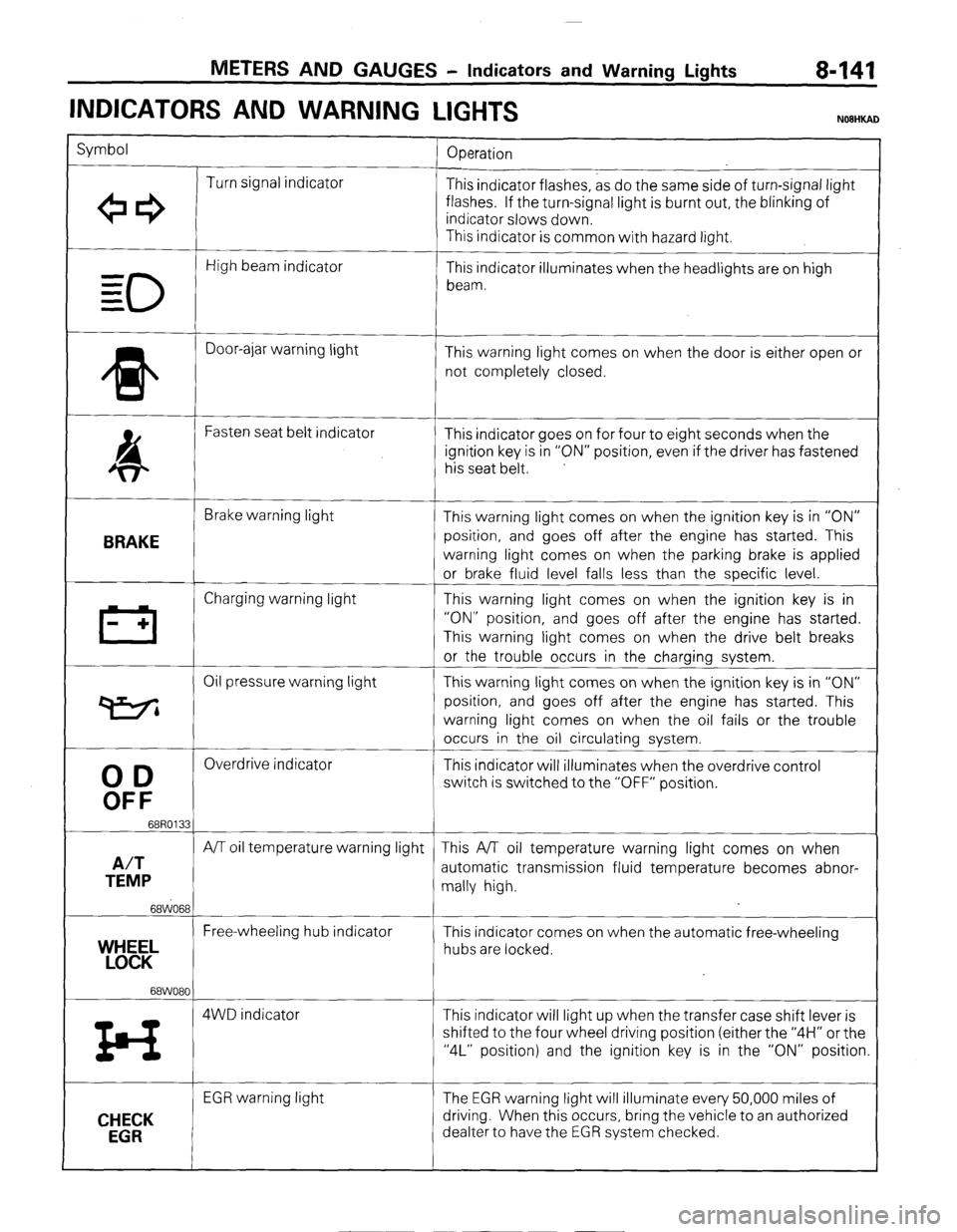
INDICATORS AND WARNING
LIGHTS
Symbol
Operation
Turn signal indicator
+e3 This indicator flashes, as do the same side of turn-signal light
flashes. If the turn-signal light is burnt out, the blinking of
indicator slows down.
This indicator is common with hazard light.
0
High beam indicator
- This indicator illuminates when the headlights are on high
= beam.
=
* Door-ajar warning light
This warning light comes on when the door is either open or
not completely closed.
4 Fasten seat belt indicator
This indicator goes on for four to eight seconds when the
ignition key is in “ON” position, even if the driver has fastened
his seat belt.
BRAKE
Brake warning light
This warning light comes on when the ignition key is in “ON”
position, and goes off after the engine has started. This
warning light comes on when the parking brake is applied
or brake fluid level falls less than the specific level.
III Charging warning light This warning light comes on when the ignition key is in
- + “ON” position, and goes off after the engine has started.
This warning light comes on when the drive belt breaks
or the trouble occurs in the charging system.
Oil pressure warning light This warning light comes on when the ignition key is in “ON”
P position, and goes off after the engine has started. This
warning light comes on when the oil fails or the trouble
occurs in the oil circulating system.
00
Overdrive indicator
This indicator will illuminates when the overdrive control
OFF
switch is switched to the “OFF” position.
68R0133
A/T
A/T oil temperature warning light This A/T oil temperature warning light comes on when
TEMP automatic transmission fluid temperature becomes abnor-
mally high.
68WO68
Free-wheeling hub indicator
YEL This indicator comes on when the automatic free-wheeling
hubs are locked.
68WO80
z4 4WD indicator This indicator will light up when the transfer case shift lever is
shifted to the four wheel driving position (either the “4H” or the
“4L” position) and the ignition key is in the “ON” position.
CHECK
EGR
EGR warning light The EGR warning light will illuminate every 50,000 miles of
driving. When this occurs, bring the vehicle to an authorized
dealter to have the EGR system checked.
) STB Revision