reset MITSUBISHI MONTERO 1987 1.G Workshop Manual
[x] Cancel search | Manufacturer: MITSUBISHI, Model Year: 1987, Model line: MONTERO, Model: MITSUBISHI MONTERO 1987 1.GPages: 284, PDF Size: 14.74 MB
Page 147 of 284

METERS AND GAUGES -Troubleshooting 8-127
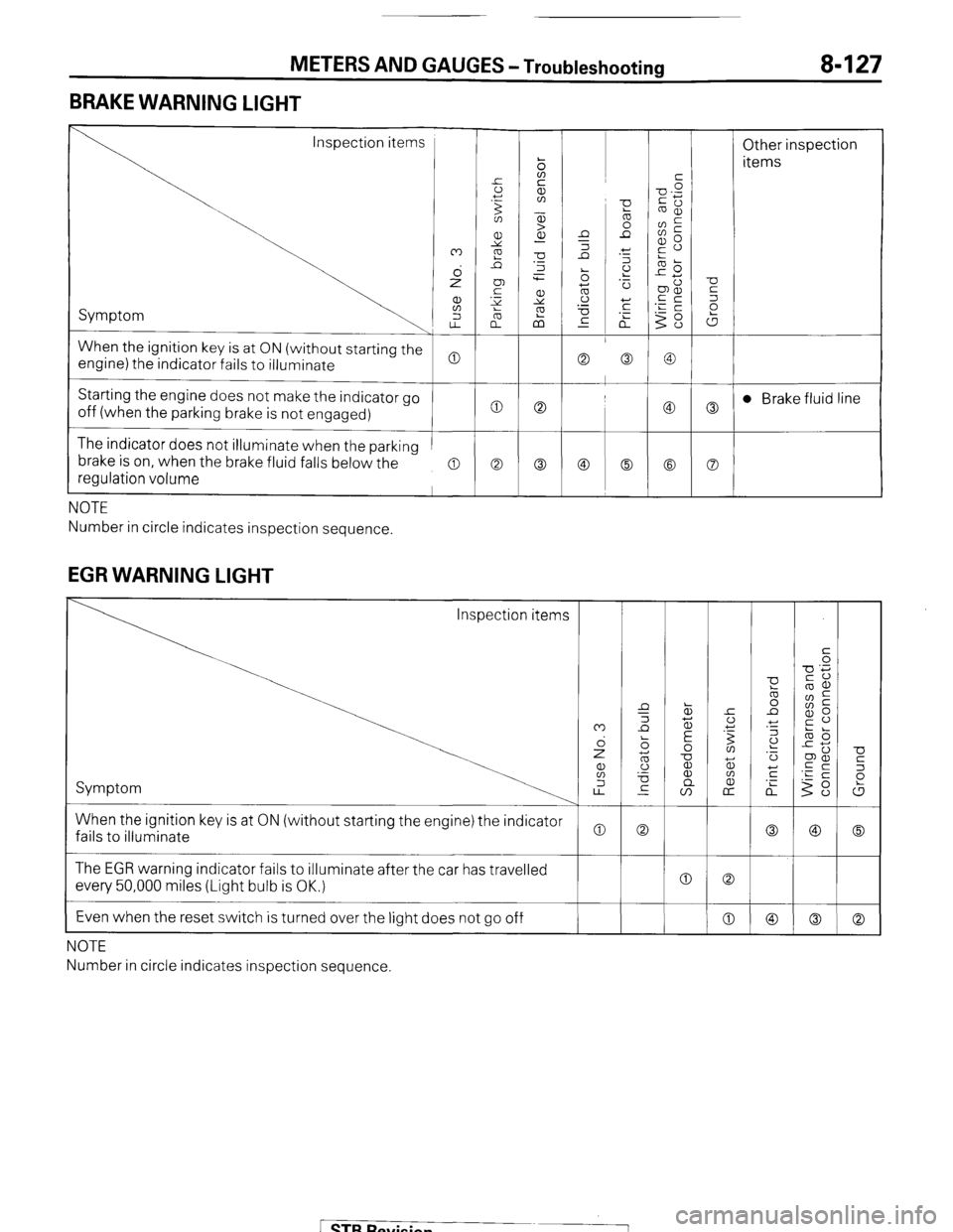
BRAKE WARNING LIGHT
Inspection items
Other inspection
items
Symptom
When the ignition key is at ON (without starting the
engine) the indicator fails to illuminate
Starting the engine does not make the indicator go
off (when the parking brake is not engaged) t 0 0
c
The indicator does not illuminate when the parking
brake is on, when the brake fluid falls below the
regulation volume
a a Co
NOTE
Number in circle indicates inspection sequence.
EGR WARNING LIGHT
U
5
P
W
0
Co When the ignition key is at ON (without starting the engine) the indicator
fails to illuminate
0 The EGR warning indicator fails to illuminate after the car has travelled
every 50,000 miles (Light bulb is OK.)
Even when the reset switch is turned over the light does not go off 0 0
0
I
NOTE
Number in circle indicates inspection sequence.
[ STB Revision
Page 162 of 284

8-142 METERS AND GAUGES - EGR Warning System
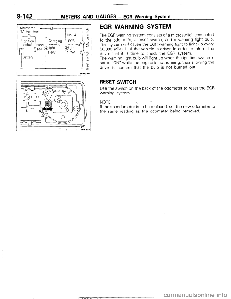
EGR WARNING SYSTEM
The EGR warning system consists of a microswitch connected
to the odometer, a reset switch, and a warning light bulb.
This system will cause the EGR warning light to light up every
50,000 miles that the vehicle is driven in order to inform the
driver that it is time to check the EGR system.
The warning light bulb will light up when the ignition switch is
set to “ON” while the engine is not running, thus allowing the
driver to confirm that the bulb is not burned out.
RESET SWITCH
Use the switch on the back of the odometer to reset the EGR
warning system.
NOTE
If the speedometer is to be replaced, set the new odometer to
the same reading as the odometer being, removed.
1 STB Revision
Page 231 of 284

AUTOMATIC FREE-WHEELING HUB INDICATOR SYSTEM - Generallnformation 8-211
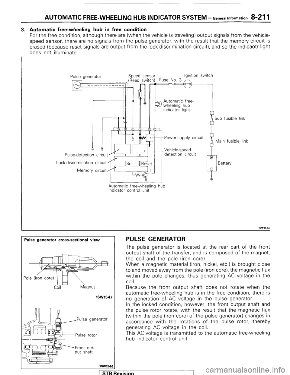
3. Automatic free-wheeling hub in free condition
For the free condition, although there are (when the vehicle is traveling) output signals from the vehicle-
speed sensor, there are no signals from the pulse generator, with the result that the memory circuit is
erased (because reset signals are output from the lock-discrimination circuit), and so the indicaotr light
does not illuminate.
I
Lock Use-detection
-discrimination
Memory ipeed sensor Ignition switch
Automatic free-
detection circuit
circuit
circuit
Automatic free-wheeling
indicator control unit -
hub i
Sub fusible link
link
Pulse generator cross-sectional view PULSE GENERATOR
Coil hgnet
16W1547
rator
Front out-
put shaft
16W1546 The pulse generator is located at the rear part of the front
output shaft of the transfer, and is composed of the magnet,
the coil and the pole (iron core).
When a magnetic material (iron, nickel, etc.) is brought close
to and moved away from the pole (iron core), the magnetic flux
within the pole changes, thus generating AC voltage in the
coil.
Because the front output shaft does not rotate when the
automatic free-wheeling hub is in the free condition, there is
no generation of AC voltage in the pulse generator.
In the locked condition, however, the front output shaft and
the pulse rotor rotate, with the result that the magnetic flux
(within the p o e I (’ Iron core) of the pulse generator) changes in
accordance with the rotations of the pulse rotor, thereby
generating AC voltage in the coil.
This AC voltage is transmitted to the automatic free-wheeling
hub indicator control unit.
STB Revision