clock MITSUBISHI MONTERO 1987 1.G Workshop Manual
[x] Cancel search | Manufacturer: MITSUBISHI, Model Year: 1987, Model line: MONTERO, Model: MITSUBISHI MONTERO 1987 1.GPages: 284, PDF Size: 14.74 MB
Page 21 of 284
8-1
ELECTRICAL
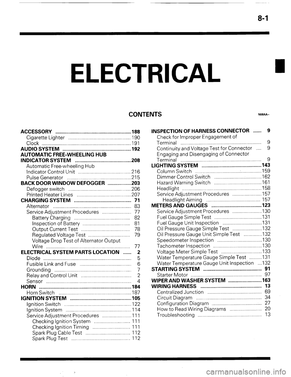
CONTENTS
NOBAA-
ACCESSORY ......................................................
188
Cigarette Lighter ............................................
,190
Clock ...............................................................
,191
AUDIO SYSTEM ................................................
.192
AUTOMATIC FREE-WHEELING HUB
INDICATOR SYSTEM ........................................
208
Automatic Free-wheeling Hub
Indicator Control Unit
..................................... ,216
Pulse Generator ..............................................
215
BACK DOOR WINDOW DEFOGGER
................ .203
Defogger switch ............................................
,206
Printed Heater Lines
...................................... ,207
CHARGING SYSTEM .........................................
71
Alternator ........................................................
83
Service Adjustment Procedures
..................... 77
Battery Charging ........................................
82
Inspection of Battery ..................................
81
Output Current Test ...................................
78
Regulated Voltage Test ..............................
79
Voltage Drop Test of Alternator Output
Wire ............................................................
77
ELECTRICAL SYSTEM PARTS LOCATION
...... 2
Diode ...............................................................
5
Fusible Link and Fuse
..................................... 6
Grounding .......................................................
7
Relay and Control Unit ....................................
2
Sensor .............................................................
4
HORN ..................................................................
184
Horn Switch
.................................................... 187
IGNITION SYSTEM ............................................
105
Ignition Switch
................................................ 122
Ignition System ...............................................
1 14
Service Adjustment Procedures
.................... .l 1 1
Checking Ignition System
..........................
11 1
Checking Ignition Timing
...........................
11 1
Spark Plug Cable Test
................................
1 12
Spark Plug Test
.......................................... 1 12 INSPECTION OF HARNESS CONNECTOR ...... 9
Check for Improper Engagement of
Terminal .......................................................... 9
Continuity and Voltage Test for Connector .... 9
Engaging and Disengaging of Connector
Terminal ..........................................................
9
LIGHTING SYSTEM ........................................... 143
Column Switch
................................ .
.............. .I59
Dimmer Control Switch
................................. .I62
Hazard Warning Switch
................................. .I61
Headlight ........................................................ ,158
Service Adjustment Procedures
.................... .I57
Headlight Aiming .......................................
157
METERS AND GAUGES .................................... 123
Service Adjustment Procedures
.................... .I30
Fuel Gauge Simple Test ................................. .I31
Fuel Gauge Unit Inspection ........................... .I31
Oil Pressure Gauge Simple Test
.................... .I32
Oil Pressure Gauge Unit Simple Test
............ ,132
Speedometer Inspection
............................... .I30
Tachometer Inspection .................................. ,130
Voltage Meter Simple Test
............................ .I33
Water Temperature Gauge Simple Test
....... ..I3 1
Water Temperature Gauge Unit Inspection
. ..I3 2
STARTING SYSTEM .......................................... 91
Starter Motor ............ ....................................... 97
WIPER AND WASHER SYSTEM
....................... .163
WIRING HARNESS ............................................ 13
Centralized Junction ....................................... 69
Circuit Diagram ............................................... 34
Configuration Diagram .................................... 27
How to Read Wiring Diagrams ....................... 20
Troubleshooting .............................................. 13
Page 52 of 284
8-32 WIRING HARNESS - Instrument Panel
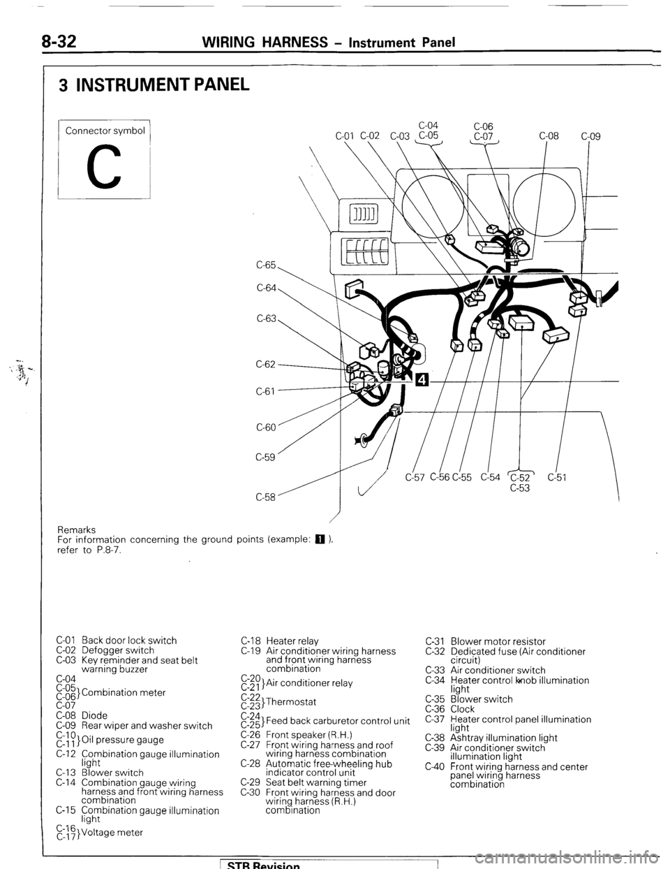
3 INSTRUMENT PANEL
Connector symbol
C
C-65 c-04
C-06
C-64
C-63
C-61
CL57 C-b6 C!55 d54 c!5
Remarks
For information concerning the ground points (example:
q ),
refer to P.8-7.
C-01 Back door lock switch
C-02 Defogger switch
C-03 Kev reminder and seat belt
warning buzzer
c-04
pi;’ Combination meter
C-08 Diode
C-09 Rear wiper and washer switch
r&~}Oil pressure gauge
C-12 f;hybination gauge illumination
C-l 3 Blower switch
C-14 Combination gauge wiring
harness and front wiring harness
combination
C-15 F;hybination gauge illumination
C,::F}Voltage meter C-l 8 Heater relay
C-l 9 Air conditioner wiring harness
and front wiring harness
combination
E:$)}Air conditioner relay C-31 Blower motor resistor
C-32 Dedicated fuse (Air conditioner
circuit)
C-33 Air conditioner switch
C-34 yl;Jer control lonob illumination
$:;;I Thermostat
$:;;I Feed back carburetor control unit
C-26 Front speaker (R.H.)
C-27 Front wiring harness and roof
wiring harness combination
C-28 Automatic free-wheeling hub
indicator control unit
C-29 Seat belt warning timer
C-30 Front wiring harness and door
wiring harness (R.H.)
combination c-35
C-36
c-37
C-38
c-39
c40
“3’ ‘. Blower switch
Clock
Heater control panel illumination
light
Ashtray illumination light
Air conditioner switch
illumination light
Front wiring harness and center
panel wiring harness
combination
[ STB Revision
Page 71 of 284
WIRING HARNESS - Instrument Panel Wumination Circuit 8-51
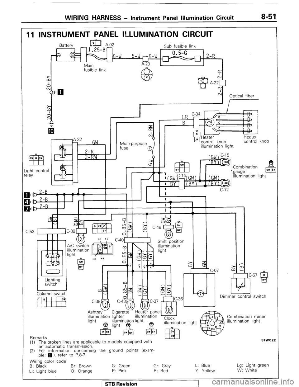
11 INSTRUMENT PANEL ILLUMINATION CIRCUIT
Battery
Sub fusible link
5-w 0.5-G
5-w l-75-W m 2-R - L-
Main A-23
fusible link
@L
M’ CA
A A-22
Y$lO rx
c-l
Optical fiber
I
I
Multi-purpose
fuse
0
3
a control knob
illumination light
.ight contr
clay
& 01 BY
7t Combination
gauge
Illumination ligl
c-4o1l Shift-position
lmer control switch
C-38
4
Ashtray
illumination Cigaretty Hegpane _
lighter illumination ’ I
minagn light Clock
n+ 63 illumination light Combination meter
illumination light
37w '62; (1) The broken lines are applicable to models equipped with
an automatic transmission.
(2) For information concerning the ground points (exam-
ple: 0 ), refer to P.8-7.
Wiring color code
B: Black Br: Brown G: Green Gr: Gray
LI: Light blue 0: Orange P: Pink R: Red L: Blue
Y: Yellow Lg: Light green
W: White
1 STB Revision
Page 82 of 284
8-62 WIRING HARNESS - Cigarette Lighter / Clock Circuit
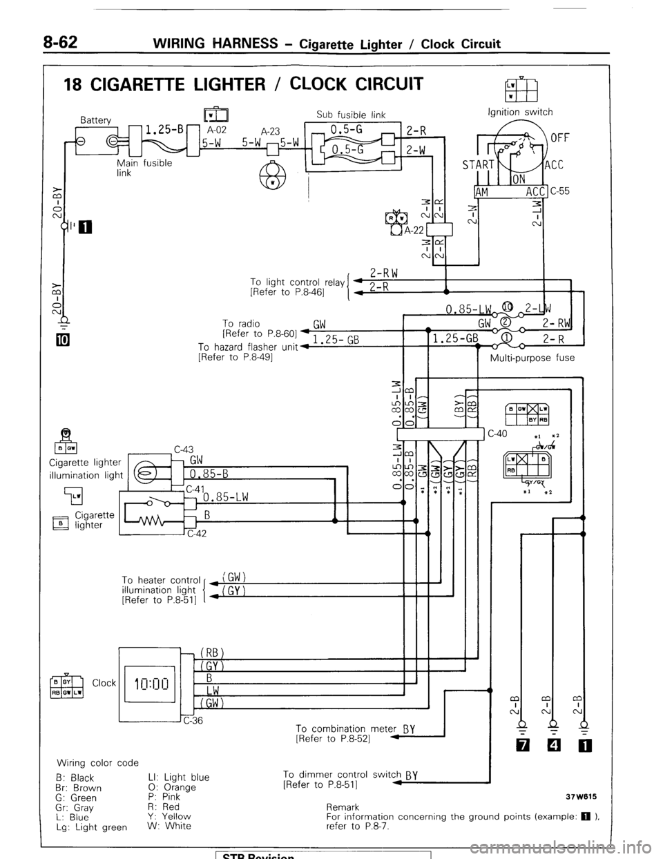
18 CIGARETTE LIGHTER / CLOCK CIRCUIT
Sub fusible link Ignition switch
r-l E-f? ‘) n
-u yn;in fusible
7-R \*I
To light control relay
[Refer to P.8-461
To radio
GW [Refer to P&601-, 3F- Pm
To hazard flasher unit4 I .LJ- G
[Refer to P.8-491
II I Multi-purpose fuse
illumination light
To heater control
illumination light
[Refer to P.8-511
Clock
CT
0: 1
h J
6
Jc-36
To combination mete& BY
[Refer to P.8-521 1
Wiring color code
B: Black LI: Light blue To dimmer control switch BY
Br: Brown 0: Orange [Refer to P.8-511 M
G: Green P: Pink
-
Gr: Gray H: Red
L: Blue Y: Yellow
Lg: Light green W: White Remark
For information concerning the ground points (example: 0 1,
refer to P.8-‘7.
Page 90 of 284
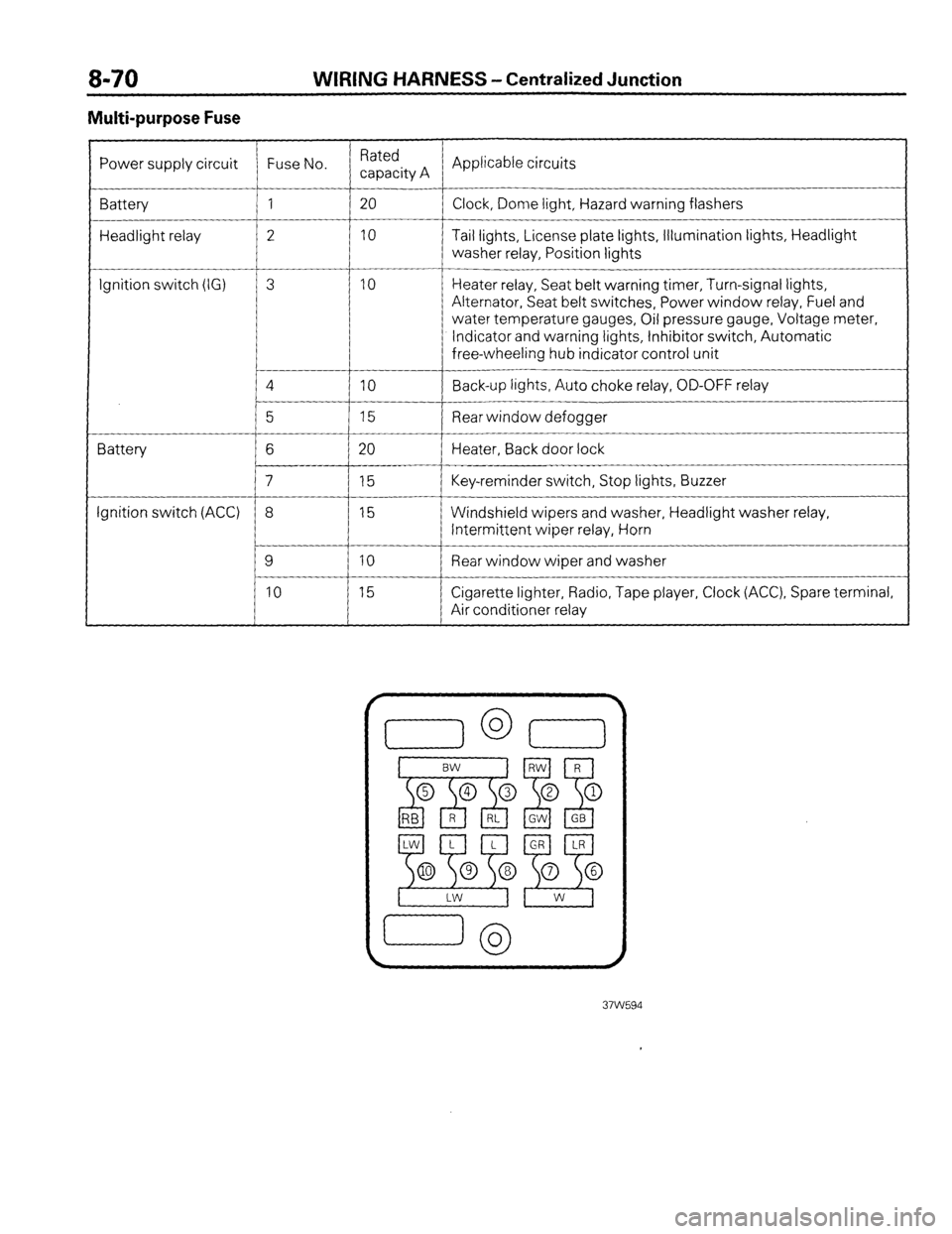
WIRING HARNESS - Centralized Junction
Multi-purpose Fuse
Power supply circuit Fuse No. Rated
capacity A Applicable circuits
Battery 1 20
Clock, Dome light, Hazard warning flashers
Headlight relay 2 10 Tail lights, License plate lights, Illumination lights, Headlight
washer relay, Position lights
__-
Ignition switch (IG) 3 10 Heater relay, Seat belt warning timer, Turn-signal lights,
Alternator, Seat belt switches, Power window relay, Fuel and
water temperature gauges, Oil pressure gauge, Voltage meter,
Indicator and warning lights, Inhibitor switch, Automatic
free-wheeling hub indicator control unit
4
IO Back-up lights, Auto choke relay, OD-OFF relay
__-
5 15 Rear window defogger
Battery 6 20 Heater, Back door lock
7 15 Key-reminder switch, Stop lights, Buzzer
Ignition switch (ACC) 8 15 Windshield wipers and washer, Headlight washer relay,
Intermittent wiper relay, Horn
9 10 Rear window wiper and washer
10 15 Cigarette lighter, Radio, Tape player, Clock (ACC), Spare terminal,
Air conditioner relay
Page 208 of 284
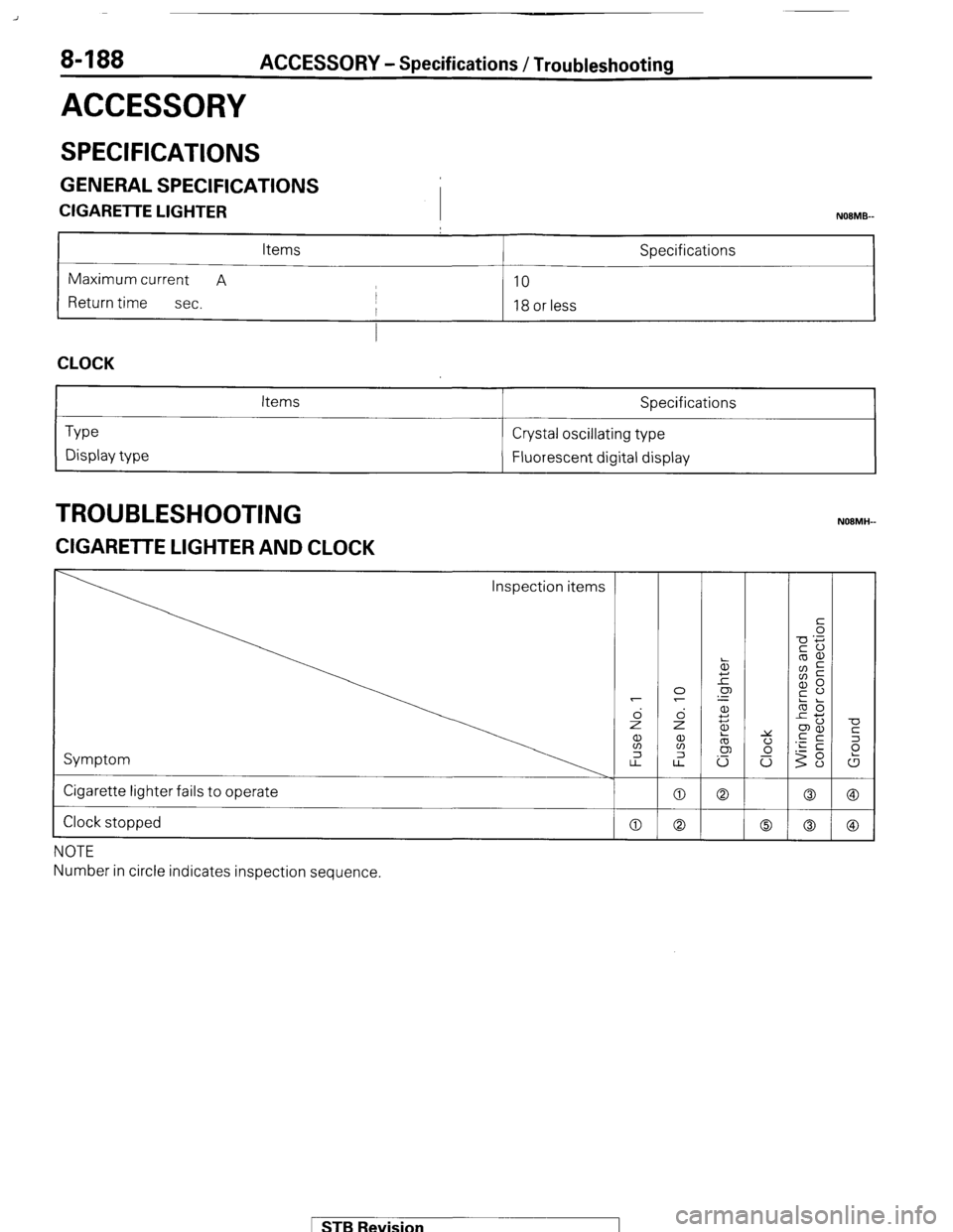
8-188 ACCESSORY - Specifications / Troubleshooting
ACCESSORY
SPECIFICATIONS
GENERAL SPECIFICATIONS
CIGARETTE LIGHTER
I NOBMB-
Items Specifications
Maximum current A
10
Return time
sec. I
I 18 or less
I
CLOCK
Type
Display type Items Specifications
Crystal oscillating type
Fluorescent digital display
TROUBLESHOOTING
ZIGARETTE LIGHTER AND CLOCK
Inspection items
Symptom
Cigarette lighter fails to operate
Clock stopped
NOTE
Number in circle indicates inspection sequence.
MB Revision
Page 209 of 284
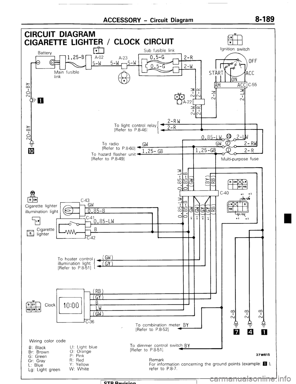
ACCESSORY - Circuit Diagram 8-189
CIRCUIT DIAGRAM
LW
CIGARETTE LIGHTER / CLOCK CIRCUIT EB w
Sub fusible link
,-fs q M 15-W 5-W 25-W m ;I;
I I
-
Main fusible -
link Ignition switch
3e
I I
NN
,
Z-RW To
linht cnntrnl r&v I 4 0 n
I 1 - .J . __._ - -., [Refer to P.8-461
I 4 L-K A
To radio
GW [Refer to P.8-601 + 1 .25- GB
To hazard flasher unit4
[Refer to P.8-491
Multi-purpose fuse
illumination light
’ To heater control
illumination light
[Refer to P 8-511
r
i I
To combination meter BY
Wiring color code
B: Black LI: Light blue
Br: Brown 0: Orange
G: Green P: Pink
Gr: Gray R: Red
L: Blue Y: Yellow
Lg: Light green W: White
I
I - - m
I
N
Q
-
[Refer to P.8-521 -
To dimmer control switch BY
[Refer to P 8-511 .I
Remark 37W615
For information concerning the ground points (example: 0 ).
refer to P.8-7.
1 STB Revision
Page 211 of 284
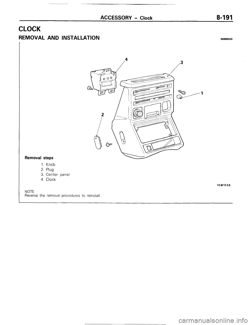
ACCESSORY - Clock 8-191
CLOCK
REMOVAL AND INSTALLATION NOBMKAD
Removal steps
1. Knob
2. Plug
3. Center panel
4. Clock
16W1558
NOTE
Reverse the removal procedures to reinstall 1 STB Revision
Page 216 of 284
8-196 AUDIO SYSTEM - Service Adjustment Procedures
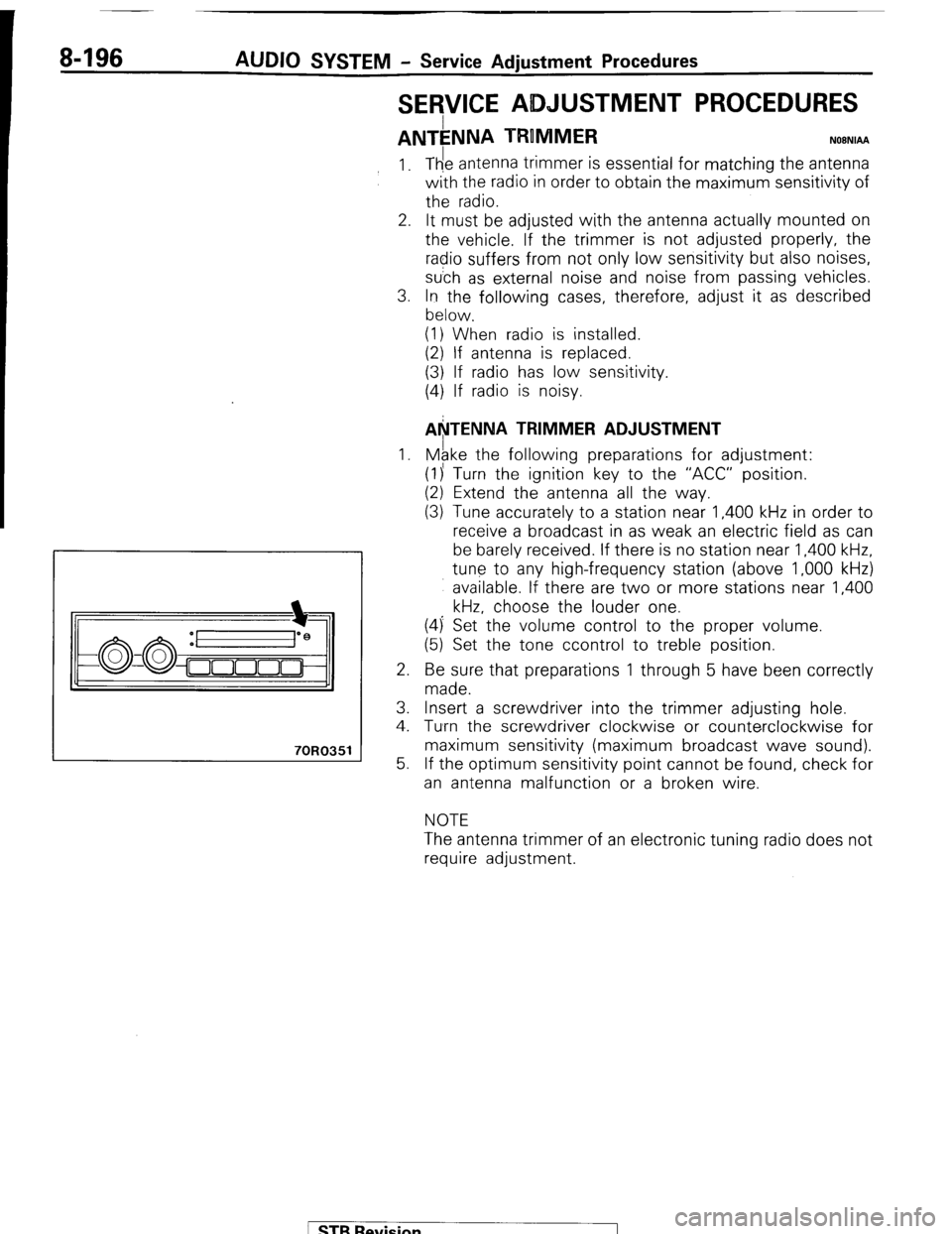
SERVICE ADJUSTMENT PROCEDURES
ANTkNNA TRUMMER NOBNIAA
70R0351
1.
2.
3.
1.
2.
3.
4.
5. The antenna trimmer is essential for matching the antenna
with the radio in order to obtain the maximum sensitivity of
the radio.
It must be adjusted with the antenna actually mounted on
the vehicle. If the trimmer is not adjusted properly, the
radio suffers from not only low sensitivity but also noises,
su’ch as external noise and noise from passing vehicles.
In the following cases, therefore, adjust it as described
below.
(1) When radio is installed.
(2) If antenna is replaced.
(3) If radio has low sensitivity.
(4) If radio is noisy.
AkTENNA TRIMMER ADJUSTMENT
Mgke the following preparations for adjustment:
(1)’ Turn the ignition key to the “ACC” position.
(2) Extend the antenna all the way.
(3) Tune accurately to a station near 1,400 kHz in order to
receive a broadcast in as weak an electric field as can
be barely received. If there is no station near 1,400 kHz,
tune to any high-frequency station (above 1,000 kHz)
available. If there are two or more stations near 1,400
kHz, choose the louder one.
(4) Set the volume control to the proper volume.
(5) Set the tone ccontrol to treble position.
Be sure that preparations 1 through 5 have been correctly
made.
Insert a screwdriver into the trimmer adjusting hole.
Tumrn the screwdriver clockwise or counterclockwise for
maximum sensitivity (maximum broadcast wave sound).
If the optimum sensitivity point cannot be found, check for
an antenna malfunction or a broken wire.
NOTE
The antenna trimmer of an electronic tuning radio does not
require adjustment.
/ STB Revision
Page 269 of 284
AIR-CONDITIONING-Service Adjustment Procedures 24-33
2080113
6
Refrigerant
Compressor
Cl”“” tester T-7
Leak
, tester
pick up
tube
b/
2OUO316
TESTING SYSTEM FOR LEAKS N24FFA8
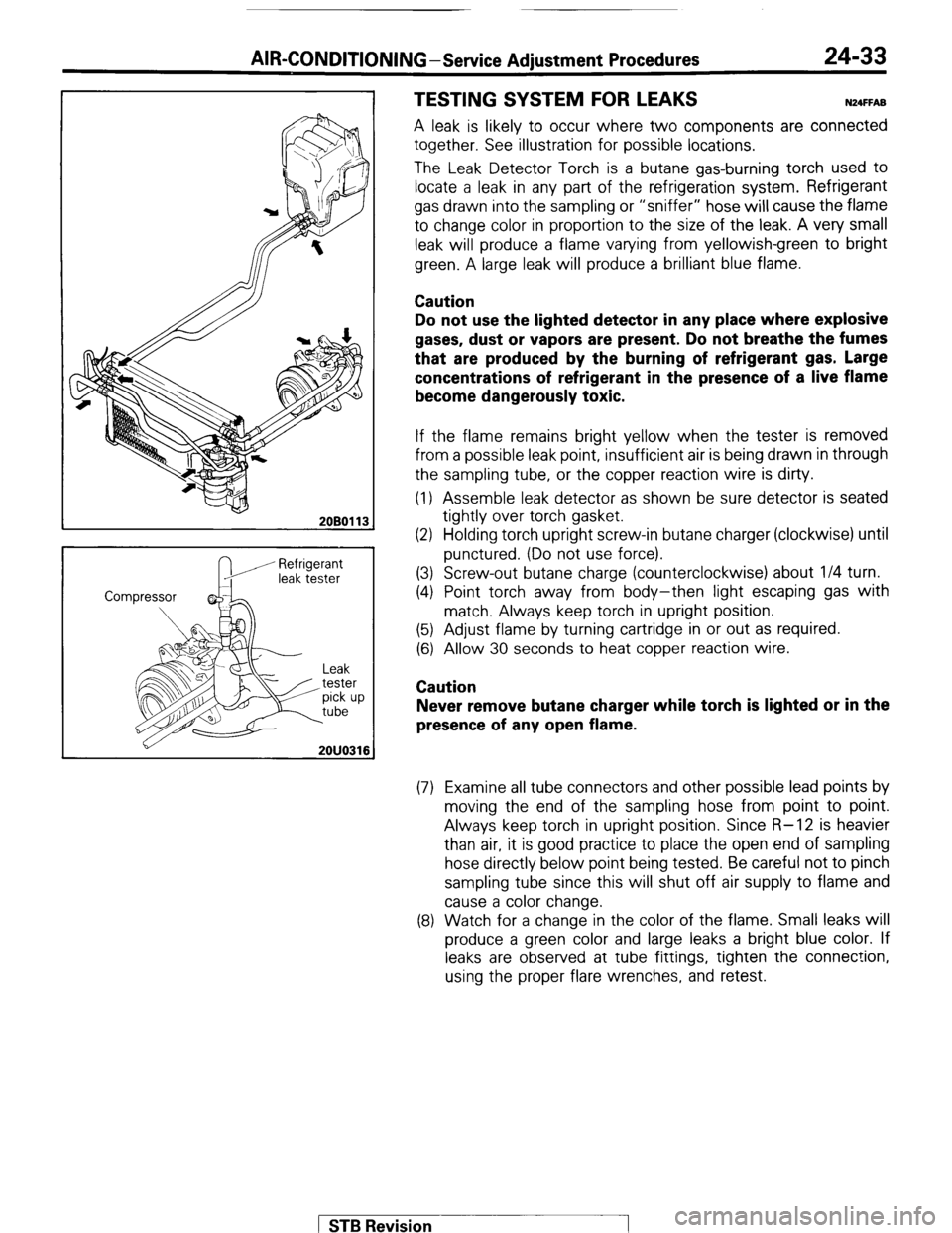
A leak is likely to occur where two components are connected
together. See illustration for possible locations.
The Leak Detector Torch is a butane gas-burning torch used to
locate a leak in any part of the refrigeration system. Refrigerant
gas drawn into the sampling or “sniffer” hose will cause the flame
to change color in proportion to the size of the leak. A very small
leak will produce a flame varying from yellowish-green to bright
green. A large leak will produce a brilliant blue flame.
Caution
Do not use the lighted detector in any place where explosive
gases, dust or vapors are present. Do not breathe the
fumes
that are produced by the burning of refrigerant gas. Large
concentrations of refrigerant in the presence of a live flame
become dangerously toxic.
If the flame remains bright yellow when the tester is removed
from a possible leak point, insufficient air is being drawn in through
the sampling tube, or the copper reaction wire is dirty.
(1) Assemble leak detector as shown be sure detector is seated
tightly over torch gasket.
(2) Holding torch upright screw-in butane charger (clockwise) until
punctured. (Do not use force).
(3) Screw-out butane charge (counterclockwise) about l/4 turn.
(4) Point torch away from body-then light escaping gas with
match. Always keep torch in upright position.
(5) Adjust flame by turning cartridge in or out as required.
(6) Allow 30 seconds to heat copper reaction wire.
Caution
Never remove butane charger while torch is lighted or in the
presence of any open flame.
(7) Examine all tube connectors and other possible lead points by
moving the end of the sampling hose from point to point.
Always keep torch in upright position. Since R-12 is heavier
than air, it is good practice to place the open end of sampling
hose directly below point being tested. Be careful not to pinch
sampling tube since this will shut off air supply to flame and
cause a color change.
(8) Watch for a change in the color of the flame. Small leaks will
produce a green color and large leaks a bright blue color. If
leaks are observed at tube fittings, tighten the connection,
using the proper flare wrenches, and retest.
1 STB Revision