resistor MITSUBISHI MONTERO 1987 1.G Workshop Manual
[x] Cancel search | Manufacturer: MITSUBISHI, Model Year: 1987, Model line: MONTERO, Model: MITSUBISHI MONTERO 1987 1.GPages: 284, PDF Size: 14.74 MB
Page 46 of 284
8-26 WIRING HARNESS - HOW to Read Wiring Diagrams
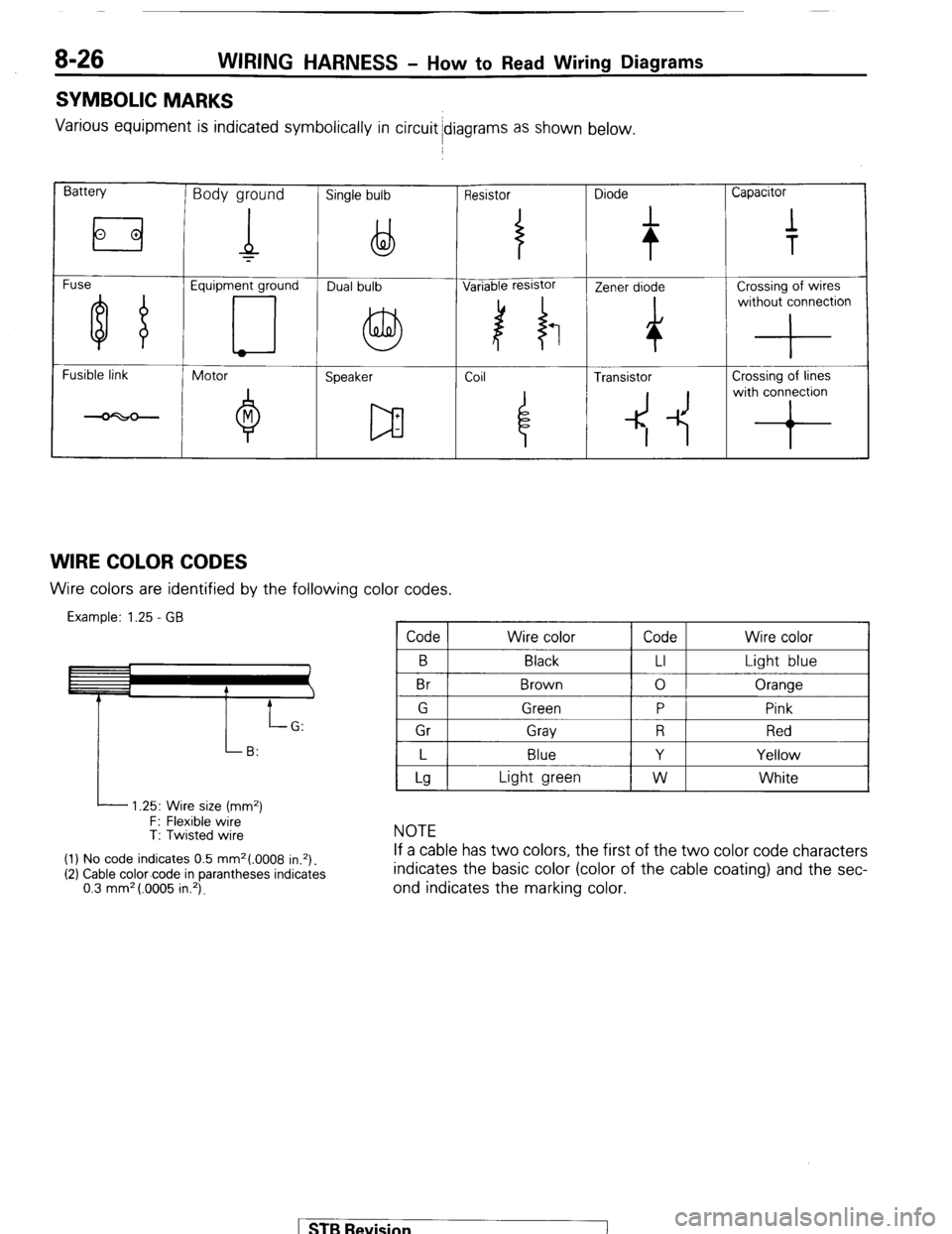
SYMBOLIC MARKS
Various equipment is indicated symbolically in circuit idiagrams as shown below.
Battery Body ground Single bulb Resistor Diode Capacitor
Fuse Equipment ground
Fusible link
Motor
Speaker Coil ~
4 Transistor Crossing of lines
4 -1~ with conron
WIRE COLOR CODES Wire colors are identified by the following color codes.
Example: 1.25 - GB Code Wire color Code Wire color
B
Br Black
Brown LI
0 Light blue
Oranqe
I P
i 1 Gr 1 Grav 1 R 1 Red I
I L I Blue
I Y I Yellow I
L 1.25: Wire size (mm2)
F: Flexible wire
T: Twisted wire
(1) No code indicates 0.5 mm2(.0008 in.*).
(2) Cable color-code in parantheses indicates
0.3 mm* (.0005 in.‘).
Lg Light green W White
NOTE
If a cable has two colors, the first of the two color code characters
indicates the basic color (color of the cable coating) and the sec-
ond indicates the marking color.
STB Revision
Page 52 of 284
8-32 WIRING HARNESS - Instrument Panel
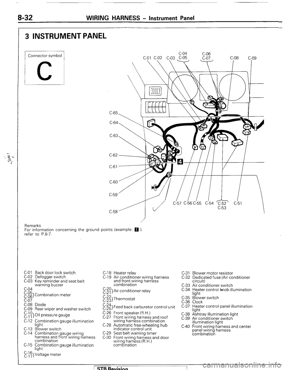
3 INSTRUMENT PANEL
Connector symbol
C
C-65 c-04
C-06
C-64
C-63
C-61
CL57 C-b6 C!55 d54 c!5
Remarks
For information concerning the ground points (example:
q ),
refer to P.8-7.
C-01 Back door lock switch
C-02 Defogger switch
C-03 Kev reminder and seat belt
warning buzzer
c-04
pi;’ Combination meter
C-08 Diode
C-09 Rear wiper and washer switch
r&~}Oil pressure gauge
C-12 f;hybination gauge illumination
C-l 3 Blower switch
C-14 Combination gauge wiring
harness and front wiring harness
combination
C-15 F;hybination gauge illumination
C,::F}Voltage meter C-l 8 Heater relay
C-l 9 Air conditioner wiring harness
and front wiring harness
combination
E:$)}Air conditioner relay C-31 Blower motor resistor
C-32 Dedicated fuse (Air conditioner
circuit)
C-33 Air conditioner switch
C-34 yl;Jer control lonob illumination
$:;;I Thermostat
$:;;I Feed back carburetor control unit
C-26 Front speaker (R.H.)
C-27 Front wiring harness and roof
wiring harness combination
C-28 Automatic free-wheeling hub
indicator control unit
C-29 Seat belt warning timer
C-30 Front wiring harness and door
wiring harness (R.H.)
combination c-35
C-36
c-37
C-38
c-39
c40
“3’ ‘. Blower switch
Clock
Heater control panel illumination
light
Ashtray illumination light
Air conditioner switch
illumination light
Front wiring harness and center
panel wiring harness
combination
[ STB Revision
Page 75 of 284
WIRING HARNESS - Heater Circuit 8-55
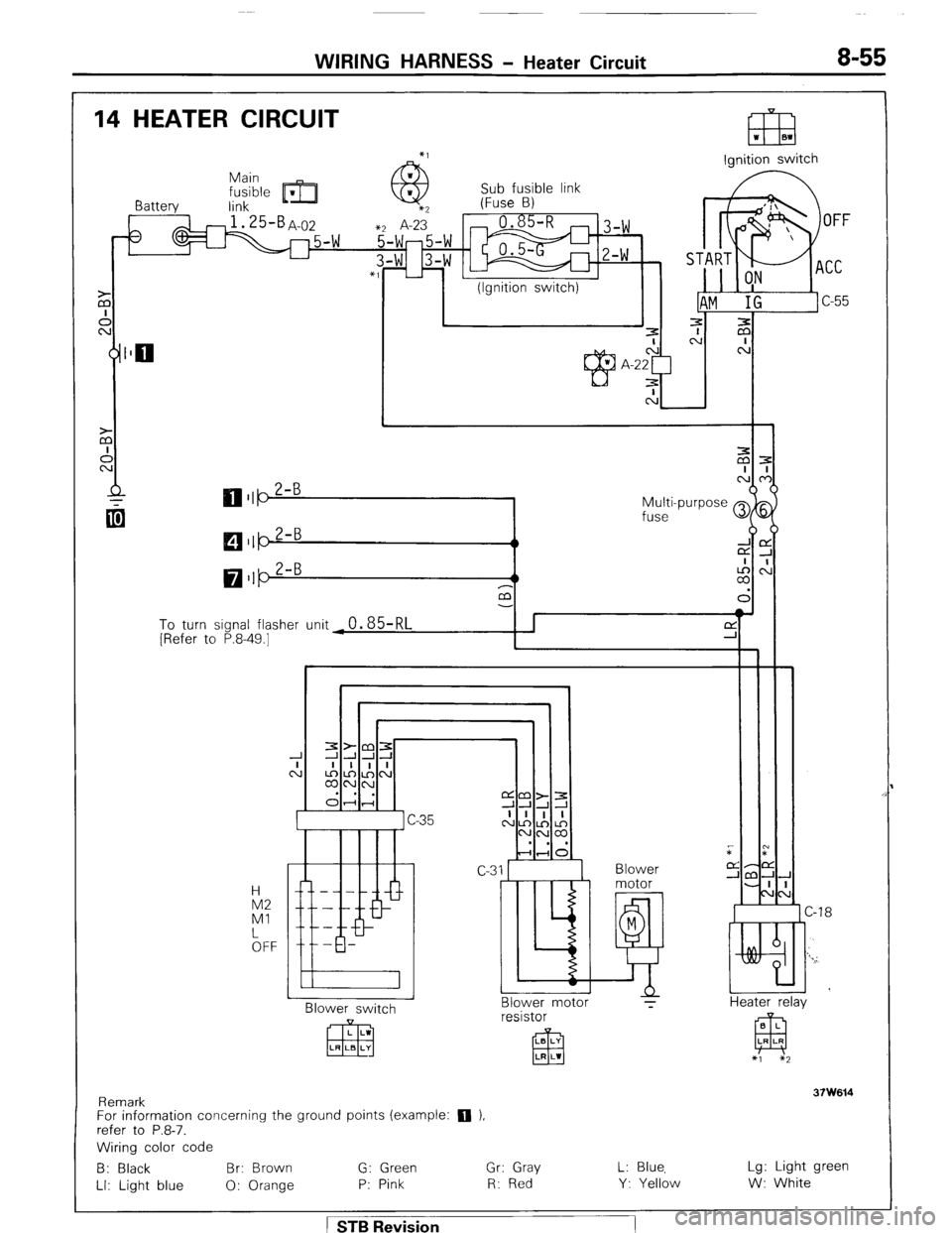
14 HEATER CIRCUIT
A’
Battery
0
(Ignition switch)
L
l!zEl *I BI
lonition switch
Multi-purpose
fuse
To turn signal flasher unit4 0.85-RL
[ [Refer to P.8-49.1
n
H
M2
Ml
bFF - -
P -
-
- -
I
Blower switch
Remark 37W614
For information concerning the ground points (example: 0 ),
refer to P.8-7.
Wiring color code
B: Black Br: Brown G: Green Gr: Gray L: Blue, Lg: Light green
LI: Light blue 0: Orange P: Pink R: Red Y: Yellow W: White Blower motor
resistor
LB LI
El3 LR LW
Blower
motor
M
!! T i
C-18
I
Heater relay
8 L
El LR LR
*1 *2
STB Revision
Page 128 of 284
8408 IGNITION SYSTEM - Specifications
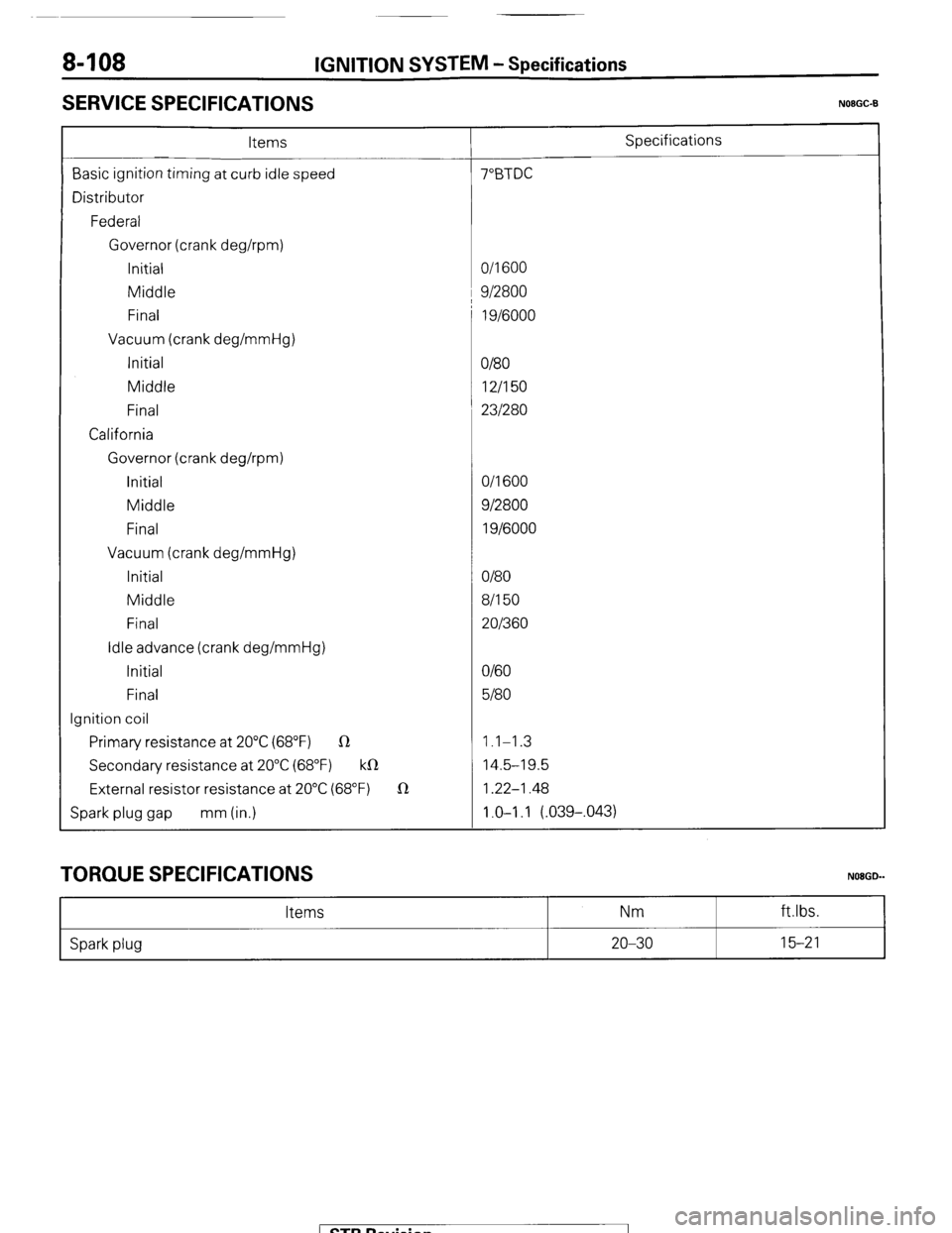
SERVICE SPECIFICATIONS
N08GC-B
Items Specifications
Basic ignition timing at curb idle speed 7”BTDC
Distributor
Federal
Governor (crank deghpm)
Initial O/l 600
Middle 1 9/2800
Final 1 g/6000
Vacuum (crank deg/mmHg)
Initial
O/80
Middle 12/I 50
Final 231280
California
Governor (crank deghpm)
initial O/l 600
Middle 912800
Final 1 g/6000
Vacuum (crank deg/mmHg)
Initial O/80
Middle 8/l 50
Final 201360
Idle advance (crank deg/mmHg)
Initial O/60
Final 5180
Ignition coil
Primary resistance at 20°C (68°F) R 1.1-1.3
Secondary resistance at 20°C (68°F) k0 14.5-19.5
External resistor resistance at 20°C (68°F) 1R 1.22-1.48
Spark plug gap mm (in.) 1.0-I .I (.039-,043)
TORQUE SPECIFICATIONS
Items Nm
NOBGD-
ft.lbs.
Spark plug 20-30 15-21
1 STB Revision
Page 136 of 284
8-116 IGNITION SYSTEM-Ignition System
Plug
cleaner
OlUOO89
Plug gap
gauge NIPPON
termine
rl
direction
High voltage
terminal
01R0234
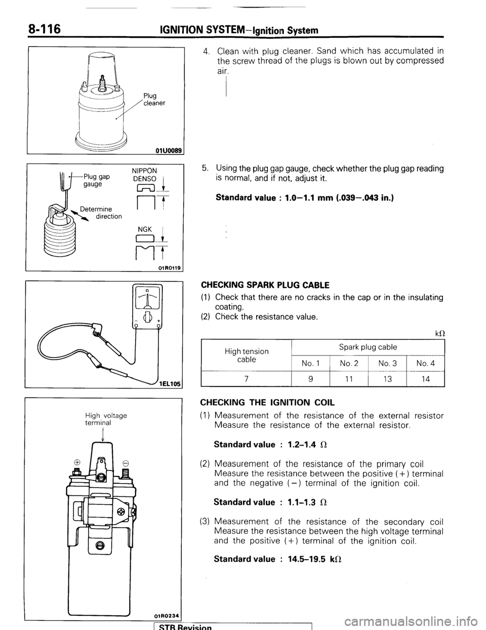
4. Clean with plug cleaner. Sand which has accumulated in
the screw thread of the plugs is blown out by compressed
air.
5. Using the plug gap gauge, check whether the plug gap reading
is normal, and if not, adjust it.
Standard value : 1.0-1.1 mm (.039-.043 in.)
CHECKING SPARK PLUG CABLE
(1) Check that there are no cracks in the cap or in the insulating
coating.
(2) Ctieck the resistance value.
High tension
cable Spark plug cable
No.1 1 No.2 1 No.3 1 No.4
I 9
I
11
I 13 I 14
CHECKING THE IGNITION COIL
(1) Measurement of the resistance of the external resistor
Measure the resistance of the external resistor. Standard value : 1.2-1.4 IR
(2) Measurement of the resistance of the primary coil
Measure the resistance between the positive (+) terminal
and the negative (-) terminal of the ignition coil. Standard value : 1.1-1.3 IR
(3) Measurement of the resistance of the secondary coil
Measure the resistance between the high voltage terminal
and the positive (+) terminal of the ignition coil. Standard value : 14.5-19.5 kfl
wision I
Page 220 of 284
8-200 AUDIO SYSTEM - Antenna/Noise Suppression
3. REMOVAL OF FRONT FENDER PANEL
Refer to GROUP 23 Body-Front Fender
SEFiVlCE ff OINTS OF INSTALLATION
3. IbSTALLATION OF FRONT FENDER PANEL
Refer to GROUP 23 Body-Front Fender.
NOISE SWPRESSION N08NOAA
I. Noise interfering with radio reception may be roughly
classified as follows:
(1) Noise produced by the vehicle itself
Noise from the ignition circuit, alternator circuit, etc
(2) Noise generated in the radio itself
Thermal noise from transistors, IC, resistor, etc.
(3) Atmospheric noise
Noise from other cars, neon signs, etc.
2. The radio has devices to suppress noise of the radio itsel f
3. and atmospheric noise, but it is difficult to eliminate them
completely. Noise produced by the vehicle includes whin-
ing from the alternator system, and a strong, impulsive,
fast popping noise from the ignition system.
Before performing any checking or adjustments, first
confirm the following points.
Adjust the antenna trimmer completely.
Set the push buttons (tuning) properly.
Extend the antenna all the way.
PREVENTION OF IGNITION CIRCUIT NOISE
A resistance-equipped cable is used for the high-tension cable
in order to prevent noise; however, if any noise from the
ignition circuit does occur, check the tightness and ground
connection of the positive (+) terminal of the noise filter, and,
if necessary, check the noise filter.
Caution
Be careful not to connect the noise filter to the hightension
cable; doing so could damage the noise filter.
PREVENTION OF OTHER CIRCUIT NOISE
1. For other noises, take necessary corrective actions in
accordance with the following items and the NOISE
SUPPRESSION CHART.
2. Polish the grounding cable terminal, and connect it proper-
ly.
3. Polish the pillar antenna ground terminal, and connect it
properly.
4. Ground electric parts completely.
5. Keep the antenna cable and speaker lead wire away from
other electric wiring.
STB Revision
Page 240 of 284
24-4 HEATERS c Circuit Diagram
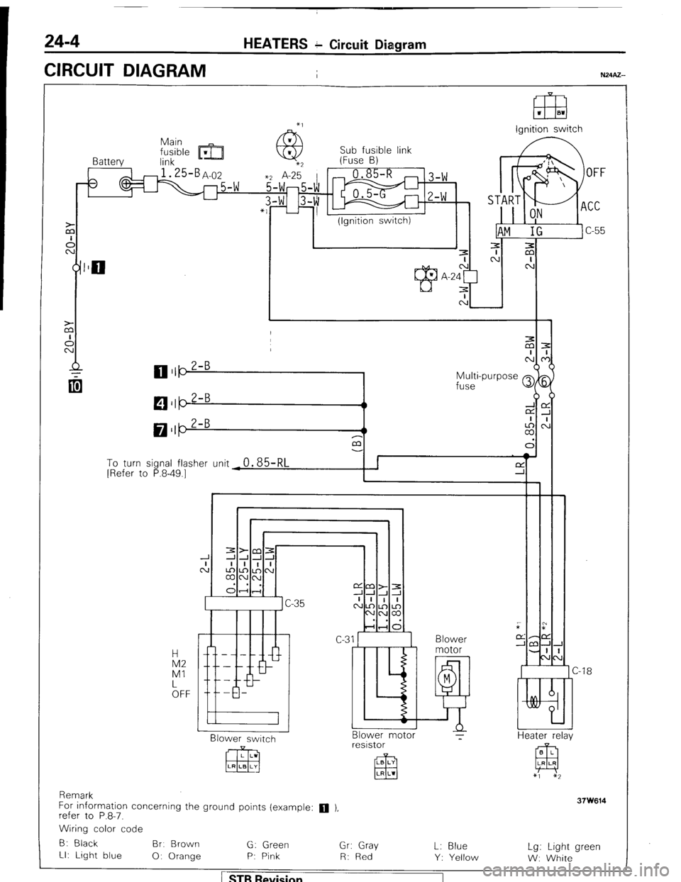
CIRCUIT DIAGRAM
I
El3 1 El1
lanition switch
Sub fusible link
Battery link m- (Fuse B)
3
1 I (Ignition switch)
Multi-purpose Q
fuse
M $5
LA,:
a3
To turn sional flasher (Init
0.85RI I I f-Y ’ I [Refer to P.8-49.7- - - ‘d -r i
I Blower
Blower switch
CJ -18
Heater r&v Blower motor ?
resistor
Remark
For information concerning the ground points (example:
q ),
refer to P.8-7.
Wiring color code
B: Black Br. Brown
G: Green
Gr: Gray
LI: Light blue
0: Orange P: Pink
R: Red L: Blue
Y: Yellow Lg: Light green
W: White
1 STB Revision
Page 250 of 284
24-14 HEATERS + Blower Assembly
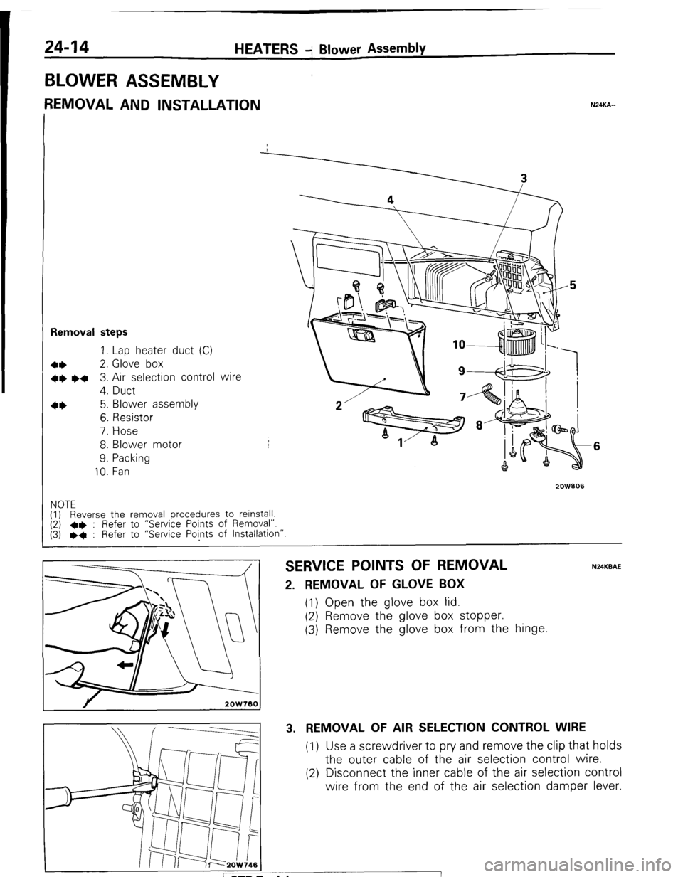
BLOWER ASSEMBLY
REMOVAL AND INSTALLATION NXKA-
Removal steps
1. Lap heater duct (C)
+* 2. Glove box
+e l + 3. Air selection control wire
4. Duct
4* 5. Blower assembly
6. Resistor
7. Hose
8. Blower motor
9. Packing
10. Fan
2oWBO6
6
NOTE
(1) Reverse the removal procedures to relnstall. (2) l * : Refer to “Service Points of Removal”.
(3) l * : Refer to “Service Points of Installation”.
SERVICE POINTS OF REMOVAL N24KBAE
2. REMOVAL OF GLOVE BOX
(1) Open the glove box lid.
(2) Remove the glove box stopper.
(3) Remove the glove box from the hinge.
3. REMOVAL OF AIR SELECTION CONTROL WIRE
(1) Use a screwdriver to pry and remove the clip that holds
the outer cable of the air selection control wire.
(2) Disconnect the inner cable of the air selection control
wire from the end of the air selection damper lever.
Page 251 of 284
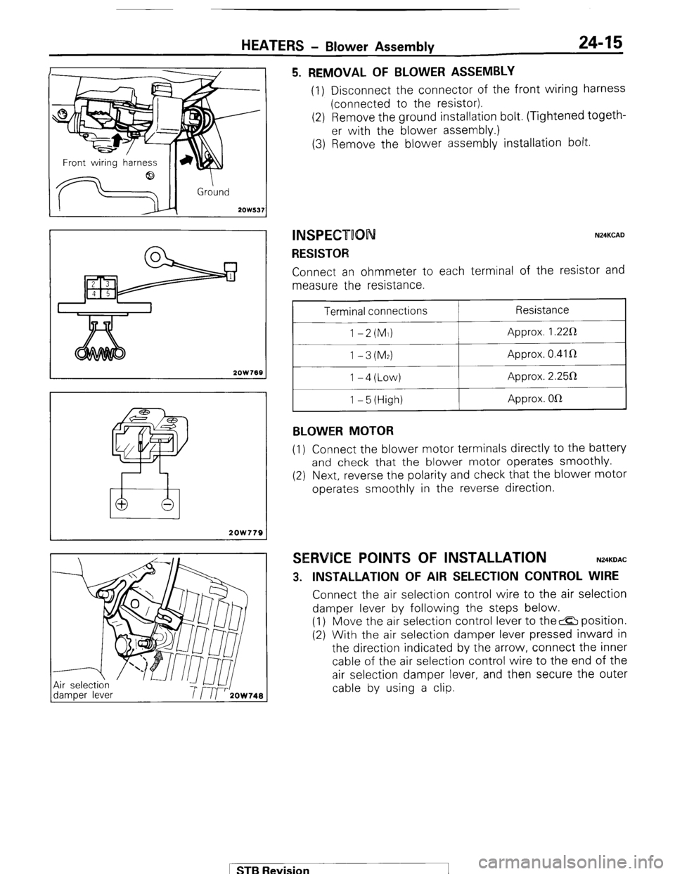
HEATERS - Blower Assembly 24-15
--I
Front wirina harness
d
!
2OW537
2OW768
2OW779
5. REMOVAL OF BLOWER ASSEMBLY (1) Disconnect the connector of the front wiring harness
(connected to the resistor).
(2) Remove the ground installation bolt. (Tightened togeth-
er with the blower assembly.)
(3) Remove the blower assembly installation bolt.
INSPECT00 N24KCAD
RESISTOR Connect an ohmmeter to each terminal of the resistor and
measure the resistance.
Terminal connections
1 -2(M1)
1 -3(M2) I-4(Low)
1 - 5 (High)
BLOWER MOTOR Resistance
Approx. 1.22R
Approx. 0.41 R
Approx. 2.25112
Approx. OlR
(1) Connect the blower motor terminals directly to the battery
and check that the blower motor operates smoothly.
(2) Next, reverse the polarity and check that the blower motor
operates smoothly in the reverse direction.
SERVICE POINTS OF INSTALLATION N24KDAC
3. INSTALLATION OF AIR SELECTION CONTROL WIRE Connect the air selection control wire to the air selection
damper lever by following the steps below.
(1) Move the air selection control lever to the& position.
(2) With the air selection damper lever pressed inward in
the direction indicated by the arrow, connect the inner
cable of the air selection control wire to the end of the
air selection damper lever, and then secure the outer
cable by using a clip.
1 STB Revision
Page 262 of 284
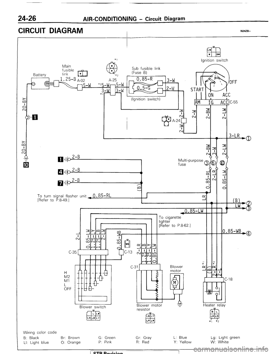
24-26 AIR-CONDITIONING - Circuit Diagram
CIRCUIT DIAGRAM I N24ZB--
Ignition switch
Main
link Sub fusible link
(Fuse B)
I Battery
3
To turn signal flasher unit ~
0.85-RL [Refer to P.8-49.1
i
I 1 ,0.85-LW F
0.85-WB*
“yl lLG1 [Refer to P.8-62.1
C-C
Blower
motor
M
E!! Blower motor
T IA2
Ml
kFF -18
Heater relav N BI ower switch B L
EEJ LR LR resistor
LB LY
El3 LR LI
x’, $2
Wiring color code
B: Black Br: Brown G: Green
Gr: Gray L: Blue Lg: Light green
LI: Light blue 0: Orange P: Pink R: Red
Y: Yellow W: White
/ ST6 Revision